Megacon Iso4-DIN User manual

pag. 1 / 8
INSTRUCTION MANUAL
IM264-U-M v0.1
Iso4-DIN
Multipoint earth leakage relay 4 inputs

pag. 2 / 8
CURRENTS
0.540 A
3.230 A
0.300 A
2.365 A
WARNING!
•Carefully read the manual before the installation or use.
•This device is to be installed by qualified personnel, complying to current standards, to avoid damages.
•Before any maintenance operation on the device, remove supply inputs.
•The manufacturer cannot be held responsible for electrical safety in case of improper use of the equipment.
•Products illustrated herein are subject to alteration and changes without
prior notice.
Description
•Earth leakage relay type A
•Measuring in true effective value (TRMS)
•Third harmonic filtering (settable)
•Modular DIN-rail housing, 3 modules
•Green power LED indicator (ON)
•External residual current transfomer
•Fail safe function for each four relays (settable)
•Visualization instant leakage values
•Backlighted LCD display (green, yellow, red)
•4 red indicator LEDs for tripping
•TEST and RESET by front button or remote contact
•Four independent relays to control the circuit breakers of the four channels
•Instantaneous bar-graph of current measurement for each channel
•Log tripped residual current
•RS-485 communication (Modbus RTU protocol)
Display and LED functions
Thanks to LCD display, the user can view very quickly the measurements (instant leakage values, filter TRMS, MAX values, THD, crest factor), the graph bar, the
Log, the alarms and can access to all settings.
•Green: detected current lower than threshold
•Yellow:
- detected current higher than PRE-ALARM threshold but lower than TRIP threshold
•Red:
- detected current higher than TRIP threshold and relay activation
- current leakage read off scale
- TEST, causes tripping of the relay
- open residual current transformer circuit (or not right connected)
Front keyboard
RESET key –To reset the relay after tripping, used to exit from settings menu.
TEST key –Causes tripping of the relays, to confirm a choice.
PROG keys –Used to enter into settings menu, to scroll display pages.
▲and ▼ keys –Used to switch between visualization modes, to select among possible choices and to modify settings (increment/decrement).
LED ON: presence of
auxiliary voltage
LCD display instant
leakage current, TRMS values,
MAX values, THD values, crest
factor, LOG and
channel’s settings
TEST pushbutton
RESET pushbutton
SETUP (▲and ▼ keys) used
to enter menu settings
TRIP LED inputs 1 - 4
▲and ▼ keys used to switch
between visualization
Channel input indication

pag. 3 / 8
Display indications
Correct display Pre-alarm display Trip display
(Green LCD) (Yellow LCD) (Red LCD)
Cause of the trip
Display message
Test
/ Red display
Current leakage
/ Red display
Others display messages
Pre-alarm
/ Yellow display
Current leakage over scale
OVR / Red display
Poor toroidal connection
OPEN / Red display
Parameters table
Below are listed all the programming parameters. For each parameter are indicated the possible setting range, the factory default, as well as a description of the
function of the parameter.
Press ▲and ▼keys to select the required parameter. The selected parameter is highlited with ►.
Press TEST key to activated the selected parameter. Use ▲and ▼ keys to select among possible choices and press TEST key to confirm a choice.
INPUTS menu
Configuration parameters for current inputs (for inputs 1…4).
INPUT ENABLE
Unit of measure
Default
Range
Enable
-
YES
YES - NO
If set to OFF, the toroidal current input is disabled.
3RD HARMONIC FILTER
Unit of measure
Default
Range
3RD filter
-
OFF
ON-OFF
Set to ON if the harmonic blocking filters for 3rd harmonic is used.
FAULT CURRENT
Unit of measure
Default
Range
I∆
mA
30
30…30000
Select the tripping fault current to earth.
LOG
10:07 15/02/2020
10:07 20/02/2020
10:07 22/02/2020
10:07 02/04/2020
10:07 09/05/2020
10:07 23/06/2020
THD
36.0%
25.0%
37.0%
35.0%
GRAPH

pag. 4 / 8
TRIPPING DELAY TIME
Unit of measure
Default
Range
Time
ms
20
20…10000
Select the tripping delay time.
RESET TRIP
Unit of measure
Default
Range
Reset
-
MAN
AUTO-MAN
If set to AUTO, the reset of TRIP will be automatic. If set to MAN, manual reset through the RESET key on the front.
PRE-ALARM DELAY TIME
Unit of measure
Default
Range
Time
ms
20
20…10000
Select the pre-alarm delay time.
PRE-ALARM THRESHOLD
Unit of measure
Default
Range
%
%
50
50…90
Select the pre-alarm threshold which is a function of the tripping fault current value.
PRE-ALARM RESET
Unit of measure
Default
Range
Reset
-
AUTO
AUTO-MAN
If set to AUTO, the reset of pre-alarm will be automatic. If set to MAN, manual reset through the RESET key on the front.
TRIP RELAY FAILSAFE
Unit of measure
Default
Range
Failsafe
-
OFF
ON-OFF
If set to ON, positive safety activated on TRIP relay of the channel input, in this condition the TRIP relay is normally energised; therefore in the event of the lack of
auxiliary voltage the output contacts move to the trip condition.
HYSTERESIS
Unit of measure
Default
Range
Hysteresis
%
90
50…90
Tripping fault current threshold hysteresis.
COMMUNICATION menu
Communication port parameters (COM1).
RS485
Unit of measure
Default
Range
Serial node address
-
01
01-247
Baudrate
bps
38400
4800-115200
Stop bits
-
1
1-2
Data format
-
8 bit - n
8 bit, no parity
8 bit, odd
8 bit, even
Response time
ms
10
5-100
UTILITY menu
UTILITY
Unit of measure
Default
Range
Language
-
ENG
ENG-ITA
Operating frequency
Hz
50
50-60
TIME and DATE menu
The ISO-4DIN manages the time and date, that is used for the storage of events (tripped current).
COMMANDS menu
The commands menu allows executing some occasional operations like resetting, log events clearing. Once the required command has been selected, press TEST
to execute it. To cancel the command execution press RESET key.
COMMAND
Description
Parameters to default
All setup parameters are resetted to factory default value
Reset MAX & TRIP
Clears the event trip memory and MAX
Reset TRIP
Clears the event trip memory
Reset MAX
Clears the MAX values
PASSWORD menu
The password is used to enable or lock to setting menu and command menu (RESET). For new devices (factory default), the password management is disabled
and the access is free. If instead the password has been enabled and defined (0-9999), then to get access, it’s necessary to enter the password first, specifyng
the number code.
PASSWORD
Unit of measure
Default
Range
Value
-
0
0-9999
If set to 0, password management is disabled.

pag. 5 / 8
Terminals connection
N°
Description
1
Trip output relay R1
2
Trip output relay R1,R2 (COMMON)
3
Trip output relay R2
4
Trip output relay R3
5
Trip output relay R3,R4 (COMMON)
6
Trip output relay R4
7
External TEST (DI1)
8
Digital input (COMMON)
9
External RESET (DI2)
10
Auxiliary supply (neutral or phase)
11
Not used
12
Auxiliary supply (neutral or phase)
13
Input toroidal current transformer 4-S1
14
Input toroidal current transformer 3,4-S2
15
Input toroidal current transformer 3-S1
16
Input toroidal current transformer 2-S1
17
Input toroidal current transformer 1,2-S2
18
Input toroidal current transformer 1-S1

pag. 6 / 8
Wiring connection
RS485 connection (optional)
12 3 4 5 6 7 8 9
10 11 12 13 14 15 16 17 18
pag. 7 / 8
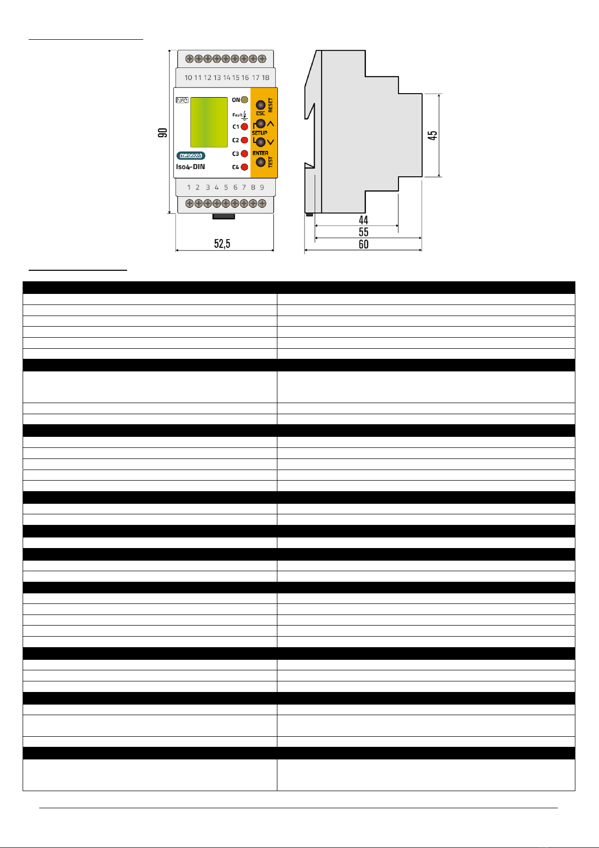
Mechanical dimensions (mm)
Technical characteristics
Control circuit
Toroidal transformer
External
Tripping type
Type A
Tripping set-point (I∆)
0,03÷30A
Prealarm set-point
50÷90%
Tripping time (t)
0,02÷10s
Resetting
Automatic or manual by pushbutton on front or remote
Auxiliary supply
Auxiliary voltage
230 VAC
115 VAC (optional)
24-48VAC/DC (optional)
Rated frequency
50/60Hz
Max power consumption
6VA
Output relay
Number of outputs
4
State
Configurable normally de-energised or energised
Rated operating voltage
250 VAC
Rated current
5A
Mechanical life
10 · 106 cycles
Digital inputs
Number of inputs
2
Rated voltage
Self powered
Display
Type
LCD
RS485 serial interface (optional)
Protocol
Modbus-RTU
Baud-rate
Programmable 4800 –115200 bps
Connections
Type of terminal
Screw (fixed)
Number of terminals
18
Conductor cross section
0,127 - 2,082 mm2
Tightening torque
0.5 - 0.6 Nm
Length of cable to strip
7mm
Ambient operating conditions
Operating temperature
-10÷60°C
Storage temperature
-20÷80°C
Relative humidity
5÷95%
Housing
Version
3 module DIN
Degree of protection
IP20 terminals
IP40 on front
Weight
200g
Certifications and compliance
Reference standards
EN 61010, EN 61000-6-2,
EN 61000-6-3, IEC/TR 60755
EN 60947-2 Annex M

pag. 8 / 8
For further details please contact:
Megacon AB
Ranhammarsvägen 20
S-168 67 Bromma, Sweden
Phone: +46 (0)8-402 42 50
www.megacon.se
Table of contents


