Megatron MRSi-x200 User manual

MRSi-x200 & MRTi-x200
3U Metal Box Printer
with paper rewinder
with EPSON dotmatrix
mechanism
•Printing mechanism
•Dot-matrix technology in 1 , 192 or 2 0 dots/line
• or 8 needles shuttle printer
•MRSi: printer with Epson M-160 mechanism
•MRTi: printer with EPSON M-190 mechanism
•Interface
•TTL serial or RS232C from 110 to 19k2 baud
•USB 2.0 Printer Class
•Ethernet
•Power Supply: DC 5 V, DC 9- 0 V or Mains
•Characteristics
•3U Metal Box printer with paper rewinder
•Self-test and hexadecimal dump
•2 characters fonts
•Graphic curve mode
•Horizontal line graphic mode.
•Real time clock
with summer / winter adjustment
User manual - version 0.3 – English

SUMMARY
1 Generalit .......................................................................................................3
1.1 Functioning.............................................................................................3
1.2 Material description................................................................................4
1.3 Part number............................................................................................5
1.4 Technical Data........................................................................................6
2 Printer Operation............................................................................................7
2.1 Start-Up..................................................................................................7
2.2 S stem Reinitialization (RESET)............................................................7
2.3 Self-test or Hexa Dump..........................................................................7
2.4 3U Rack With Paper Rewinder (MRxi-x2xx)..........................................8
2.4.1 Paper End.......................................................................................9
2.4.2 Status Led......................................................................................9
2.4.3 Replacing of the Ink Cartridge:.....................................................10
2.4.4 Replacing the paper :....................................................................11
2.4.5 Fixing............................................................................................12
2.4.6 Size...............................................................................................13
3 Driver installation..........................................................................................14
3.1 Windows...............................................................................................14
4 Wiring Information........................................................................................17
4.1 Board connections................................................................................17
5 Configuration menu......................................................................................18
6 Fonts & Control codes..................................................................................23
6.1 Character Sets......................................................................................23
6.2 Control codes PCL Raw.......................................................................23
6.3 Control codes ESC/P 9 PINS...............................................................24
6.4 Control code ESC/P Basic...................................................................24
6.5 Control code MRS & MP-181...............................................................25
7 Annexe.........................................................................................................26
7.1 Cables and Consumables....................................................................26
MRSi & MRTi – x2xx v0.3 2

1 GENERALITY
1.1 FUNCTIONING
Most of the printers available on the market allow printing data, text or graphic
supplied b a computer or a PLC. When designing the MRSi and MRTi
printers, we took into account man special requests from our customers in
order to design the most universal O.E.M printer available toda .
Several housings are available in order to integrate these printers on
machine front panel or a 3U equipment
With its dotmatrix technolog , this printer is the right solution for tracabilit
applications, when a long preservation of the ticket is required.
Man features are included in the printer software allowing graphic printing
and a lot of special effects:
Bonus:
●Compatibilit : with printer language like Epson ESC/P 9 pins,
HP PCL Raw or Megatron MRS
●2 character fonts in 6x10 and 10x10 matrix
●Selftest and Hexadecimal dump to debugging the interface
●Windows 2K / XP and Vista 32 driver available on our website
www.megatron.fr.
3 MRSi & MRTi – x2xx v0.3
AGREEMENTS
Because of the evolution of standards and technologies and in
a permanent concern of improvement, the contents of this
manual are subject to change without notice.

1.2 MATERIAL DESCRIPTION
The printer is designed around a PSD3434E microprocessor, with 7K-B tes of
RAM available for buffering datas. An internal watchdog in the microprocessor is
activated to insure an operation in strongl polluted industrial environment.
Printing heads: 2 kinds of head can be used :
- MRSi printers are equipped with Epson M-160 dot-matrix head famil with 4
needles allowing slow graphic printings with long dela between lines
- MRTi printers are equipped with Epson M-190 dot-matrix head famil with 8
needles allowing fast text or graphic printings
Serial Interface: The printer can be connected in serial in TTL or RS232C levels.
Hardware (RTS/CTS) and software (XON/XOFF) handshakes are simultaneousl
supported.
USB 2.0: The printer can be connected in USB 2.0 at full speed. Printer class
(class 7) is supported.
Accessories: Several accessories like Line-Feed button, control LED, paper-end
detector and rewinder are directl managed b MRSi and MRTi printers.
Power Supply: Depending of the model, VCC power suppl must be suppl in
DC 5 V, DC 9 to 40 V or Mains.
MRSi & MRTi – x2xx v0.3 4

1.3 PART NUMBER
Several versions of the electronics and cases are available. To completel define
our product, it is necessar to add a suffix to the name of the printer to specif
the printer t pe, the selected computer connection, the power suppl and the
clock option.
M R x i - x1x2x3x- xc
Head Family
Dot-matrix with 4 needles: M-160 : [S]
Dot-matrix with 8 needles: M-190 : [T]
Characters by line
144 dots / line : [2]
192 dots / line : [3]
240 dots / line : [4]
Kind of case
No case : [0]
3U panel case without paper rewinder : [1]
3U panel case with paper rewinder : [2]
Panel mounting case with drawer : [3]
Black plastic case : [4]
Interface
Serial TTL (level 0-5V) : [1]
Serial RS232C (level ±12V) : [2]
USB 2.0 interface : [6]
Ethernet interface : [7]
Power Supply
DC 5 V : [1]
Mains 230 VAC - 50/60 Hz(*) : [2]
DC 9 to 40 V : [3]
Clock option
installed : [C]
not installed : [ ]
(*) Mains suppl is actuall under developpment. An order of a MRxi-xxx2 will
be temporaril delivered with MRxi-xxx1 with a separated Mains Suppl .
5 MRSi & MRTi – x2xx v0.3

1. TECHNICAL DATA
Serial Interface TTL serial
RS232C/V24 serial
Handshake Xon/Xoff and RTS/CTS
USB Interface USB 2.0, Printer Class
Working temperature 0 to 50°C
Power supply (model depending) 5 VDC 9- 0VDC 5 VDC 9- 0 VDC
Consumption at 5V at 12V at 5V at 12V
Waiting < 0,1A < 0,1A < 0,1A < 0,1A
Average 0,8 A 0,5 A 2,5 A 0,7 A
Peak 1,5 A 1 A 5,5 A 2,3 A
Model MRSi MRSi MRTi MRTi
MRSi MRTi
Print Heads 2xxx 3xxx 4xxx 2xxx 3xxx 4xxx
Reference M-160 M-161 M-162 M-190 M-191 M-192
Dots / line 144 192 240 144 192 240
Text printing speed ~ 0,7 l/s ~ 0,5 l/s ~ 0,4 l/s ~ 2,5 l/s ~ 1,9 l/s ~ 1,5 l/s
MCBF (lines) ~ 500K ~ 500K ~ 500K ~ 1 500K ~ 1 100K ~ 900K
Character Set IBM-II
in matrix 6 x 10 dots (v*h)
MRSi & MRTi
2xxx 3xxx 4xxx
Chars/line 24 32 40
Chars. width (mm) 2,0 1,5 1,2
Chars Height (mm) 2,6 2,6 2,6
Character Set IBM-II
in matrix 10 x 10 dots (v*h)
MRSi & MRTi
2xxx 3xxx 4xxx
Chars/line 14 19 24
Chars. width (mm) 3,3 2,5 2,0
Chars Height (mm) 2,6 2,6 2,6
MRSi & MRTi – x2xx v0.3 6

2 PRINTER OPERATION
2.1 START-UP
1. Connect the power suppl and connection cables
2. Turn power on
The interface will control its memor , set its parameters according to the data
menu stored in its Flash memor , look for the possible presence of a clock
circuit and moves the printing head for one line to determine the dot number
of the connected head. At the end of this initialization c cle, the printer is
read for receiving characters.
2.2 SYSTEM REINITIALIZATION (RESET)
The printer is designed with a watchdog which makes a reset at power-up
authorizing the use of a slow ascent suppl . About 300 milli-seconds after the
controller is powered-up, this one is read for operation, having ended its
reset c cle.
2.3 SELF-TEST OR HEXA DUMP
If, after a reset or at power-up, the linefeed
button is maintained pushed, a self-test
c cle is run. The printer prints its name.
At this time if ou :
●continue pressing the LF button,
the hexadecimal dump mode is
invoked. A message 'DUMP HEXA
MODE' is printed. Release the LF
button. Now the value of all the
received data will be printed in
Hexadecimal followed b their
ASCII value if printable. Power-off
the printer to leave this mode.
●release the LF button, all the
parameter settings and the
character set are printed. At the end
of the self-test the printer will work
normall .
The self-test gives onl a probabilit of correct operation of the printer; indeed,
the self-test procedure does not use transmission, this one can onl be tested
in real mode.
7 MRSi & MRTi – x2xx v0.3

2. 3U RACK WITH PAPER REWINDER (MRXI-X2XX)
This case is a small mono-block case
integrating a printing head, a paper roll
support and a paper rewinder.
This case is compatible with the EURODIN
standard and can be directl installed in a
3U s stem rack.
The interface is fixed at the back of the
case making an autonomous and
compact product. The front door can be
opened to give access to the paper roll.
The ink cartridge can be changed b
removing the first part of the door.
The dimensions of this printer are identical to those of the previous printer.
The same printer exists without a paper rewinder. For more information about
this product, refer to MRSi-x1xx and MRTi-x1xx documentation.
MRSi & MRTi – x2xx v0.3 8

2. .1 Paper End
If a paper-end occurs, the red LED will blink
and the printout is hanging.
Depending of the « No Paper » menu setting,
the paper defect can :
●be totall ignored (ignored)
●stop the printout but can accept the
data until the buffer is full (Fill Buff.)
●stop the printout and stop the data
transmission (Set Bus )
2. .2 Status Led
A status LED informs the user of the possible defects of operation.
When this led is out, it indicates a correct operation, a blinking LED indicates
an abnormal status which is explained in the table below:
LED C cle Description S stem
Ällllllllllllllll ÅCorrect operation No
Äl¡l¡l¡l¡l¡l¡l¡l¡ ÅPaper End No
Äl l l l l l l l l¡l¡l¡l¡ ÅPrinting head defect Yes
Äl l l l l l l l l¡l¡l l l l ÅRAM memor defect Yes
Älllllllll¡llllll ÅMenu activated Yes
LED period : 80 msec .
The user can drive directl the red LED with the software command.
But the 's stem' status is priorit and can't be inhibited.
9 MRSi & MRTi – x2xx v0.3
To open the case,
unscrew these two screws
below

2. .3 Replacing of the Ink Cartridge:
1. Tear off the rewinded paper .
2. Unscrew the two unremovable screws (1 and 2). The panel ( 3 ), in front
of the revolving door, can then be removed giving access to the ink
cartridge ( 4 ).
3. On the left part of the ink cartridge( 4 ) is a marked carving " PUSH ";
press on this carving, the ink cartridge lifts up itself then take it off.
4. Insert a new cartridge b watching if the paper goes between the ink band
and the bod of the cartridge. Position the cartridge so that the button of
tension of the ribbon is in front of its spur of training. Press on the two
extremities of the cartridge which go in the right position and a light click
sound indicates that it is correctl set.
5. Pull about 20 cm of paper towards the outside thanks to the paper feed
button (if the printer is not under power, it is possible to pull the paper b
hand under the condition of not pulling it too fast).
6. Put back the panel ( 3 ) having made the paper cross through the
plexiglas window ( 5 ). Plug the low part of the panel at the top of the door
hinge (6) then stick it to the revolving door.
7. Put the two unremovable screws (1 and 2) in the revolving door without
screwing them
8. Open then the revolving door ( 7 ) of the printer which gives access to the
paper rewinder ( 10 ). Remove the freezing fork of the paper rewinder b
pulling it to the left. Then remove all the rewinded paper from the paper
rewinder.
9. Place the extremit of the paper against the central pit of the rewinder
( 10 ) and block it with the blocking fork.
10. Close the revolving door ( 7 ) and completel screw the two unremovable
screws (1 and 2)
MRSi & MRTi – x2xx v0.3 10

2. . Replacing the paper :
1. Tear off the rewinded paper first.
2. Unscrew the two unremovable screws (1 and 2). The panel ( 3 ), in front
of the revolving door, can then be removed.
3. Open the revolving door ( 7 ) giving access inside the printer.
4. Tear the paper coming from the paper roll ( 8 ). For a moment close the
revolving door and remove the paper sta ing in the printing head.
5. Remove the old paper roll and its paper axis from the paper holder.
6. Make a frank cut at the end of the new paper roll, but do not install it on
the support (printing would start immediatel ). The strip of paper must
hang forward to the roll. Insert the extremit of the paper between the two
lips of the printing head ( 9): the first lip is in plastic and the second is in
metal.
Put the strip of paper between the paper rewinder ( 10 ) and the back of
the printing head ( 11 ).
7. Make a paper advance while maintaining engaged the paper.
8. Introduce the paper axis into the new roll. Insert both into the paper
holder.
9. Then follow the procedure " REPLACING OF THE INK CARTRIDGE"
from step 5..
11 MRSi & MRTi – x2xx v0.3

2. .5 Fixing
MRxi-x2xx case fits directl in a 3U rack s stem or can be accommodated in
a panel where a window was cut. 4 elongated holes in the front panel allow
for an eas mounting of the printer.
The printer MRxi-x2xx can be directl embedded in a panel where a window
(106.5 x 115 mm) and 4 x M3.2 holes were practiced.
Introduce the case b the front of the panel.
Screw the four fixation screws until obtain a freezing mechanics of the case
against the panel.
MRSi & MRTi – x2xx v0.3 12

2. .6 Size
Designation Width Height Depth D Supply
Case alone 106.5 mm 129 mm 113 mm None
MRxi-x2x1 cases 106.5 mm 129 mm 150 mm 5 VDC
MRxi-x2x3 cases 106.5 mm 129 mm 150 mm 9 to 40 VDC
(*) Mains suppl is actuall under developpment. An order of a MRxi-xxx2 will
be temporaril delivered with MRxi-xxx1 with a separated Mains Suppl .
13 MRSi & MRTi – x2xx v0.3
3 DRIVER INSTALLATION
3.1 WINDOWS
A windows driver for Windows 2000, XP, Vista32 is available on our website.
●Unzip it on a folder then connect the printer to our computer.
Printer name used in the driver is the beginning of the printer
reference; e.g.: MRSi-2, MRSi-3, MRSi-4, MRTi-2, MRTi-3, MRTi-4
●Add new printer and set the driver path with the folder parth
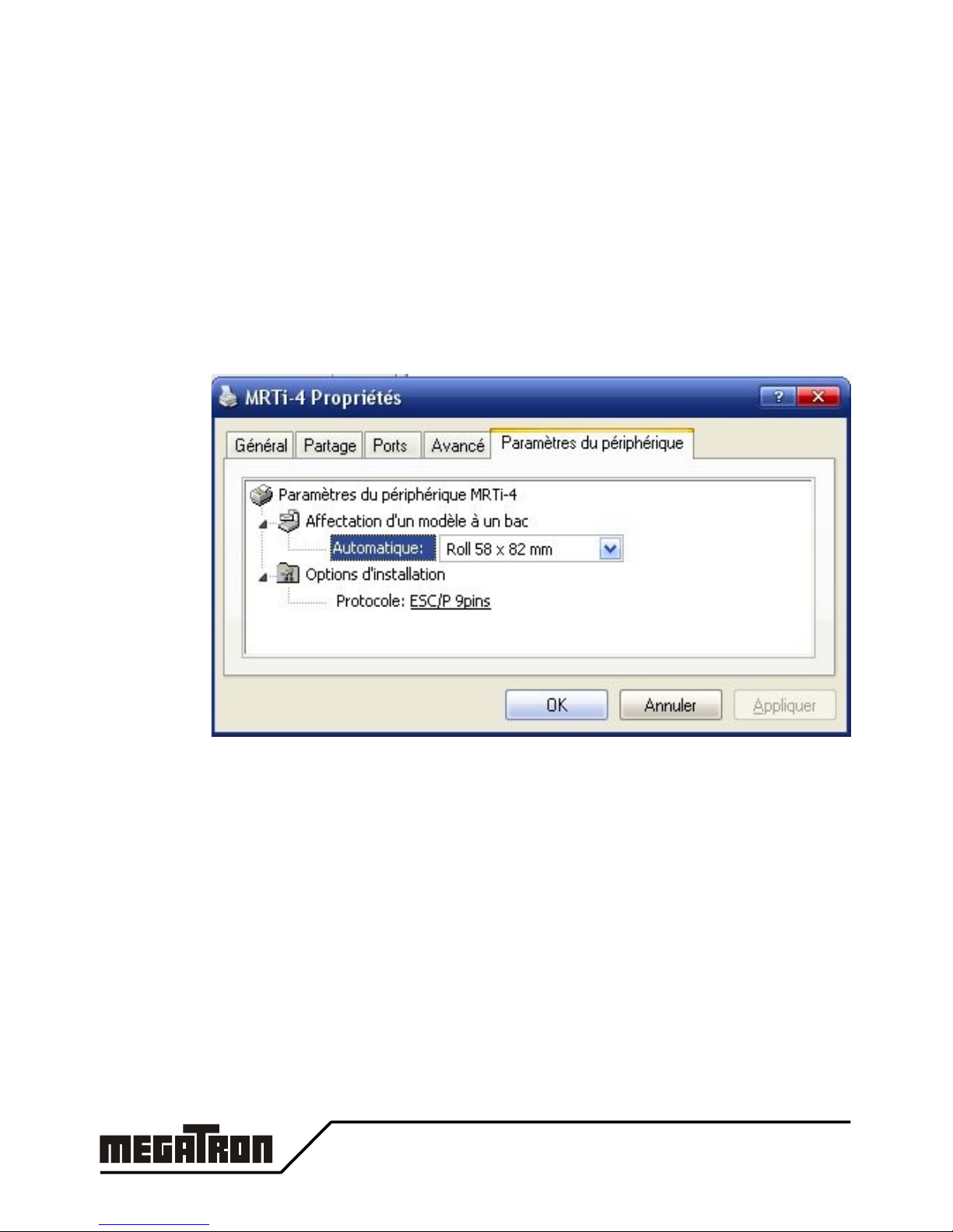
●After installation, set the driver properties accordingl to our
requirements.
●Paper Size: Roll 58x82 mm, Roll 58x150 mm, Roll 58x210 mm
●protocole: ESC/P 9pins, ESC/P Basic, PCL Raw
●In the windows applications, set the paper size to 5,8 cm width with
left and right margins at 0,5 cm.
No Top and bottom margins are necessar .
MRSi & MRTi – x2xx v0.3 14

Serial:
the printer is not automaticall detected.
●click on "add new printer" in the
Printer and Fax folder.
●Select a local Printer
●In the 'Select Printer Port"
window,
select the right serial Port
(Com1.. ComX)
●Then continue to install the printer
driver as usual
●When the installation is finished, ou
must set the settings of the serial port
accordingl with the printer in the the
printer driver properties : Baud rate,
Data Bits, Parit , Stop bits, Flow
Control.
Don't forget to set the Flow Control to Hardware or Xon/Xoff
USB:
When ou connect an USB printer to windows (2K/XP/Vista32), the OS
automaticall detect it ans will ask ou to install the correct driver.
15 MRSi & MRTi – x2xx v0.3

Ethernet: Driver installation is usual except that ou need to install a new port
on our computer.
●In the printer and Fax window, click on "add new printer".
●Select a local Printer
●In the 'Select Printer Port" window, select "Create a new port"
and choose "Standard TCP/IP Port"
●In the "Add Port" Window, fill "IP address" with the address
ou find previousl in the Lantronic Device Installer or ou
fixed in chapter " Change Module Settings". A name is
automaticall filled, ou can change it if ou want.
●In the "More Port Information are necessar ", select
"Standard: Generic Network Card"
●Then continue to install the printer driver as usual
MRSi & MRTi – x2xx v0.3 16

WIRING INFORMATION
.1 BOARD CONNECTIONS
Fast connections
POWER
MRxi-xxx1 Connect the DC 5V power suppl in J10 or J12
MRxi-xxx2 Plug the secondar of the Mains power suppl adapter in
J10 or J12
MRxi-xxx3 Connect the DC 9 to 40V power suppl in J10 or J12
Associated connector: Miniconnec MC 1,5/2-ST-3,81 from Phoenix-Contact.
INTERFACE
MRxi-xx1x Connect TTL serial interface in J6
all signals must be in TTL level (0 to 5V).
MRxi-xx2x Connect RS232 serial interface in J6
all signals must be in RS232 level (-12 to +12V).
Maxi-xx6x Connect USB 2.0 interface in J11 (mini-USB B)
This interface is a "Printer Class" (class 7)
MRxi-xx7x Connect Ethernet interface in J13 (RJ-45)
Set Serial parameters with the configuration menu.
No parameters are necessar for the USB interface.
17 MRSi & MRTi – x2xx v0.3
USB Ethernet POWER
J11 or J7 J13 J12, J10
Serial
J6
Panel
J4 or
J3
J9: 8 needles printer M-190 J2
J8: 4 needles printer M-160

5 CONFIGURATION MENU
Two different wa s are available to configure the printer:
•b the interface (see command esc ])
•b a printed configuration menu.
Here is described the printed configuration menu.
All the navigation in the Menu is made thanks to the LF push button.
Long push on the button is written <<LF>> and short push is written >LF<.
To indicate several short pushes, >LF< is followed b the quantit : >LF x2<
Activation: To activate the Configuration Menu, shortl press 4 times the
Paper Feed button ( >LF x2< ). A 'MENU ACTIVATED' message is then
printed and the first group of configuration items are printed too..
Navigation: In order to modif the settings the following steps have to be
followed:
•navigate through the groups (1)
•navigate through the different items of the group (2)
•modif the value of the items (3)
Timeout: To avoid lock of the printer in the configuration Menu, if no actions
are made on the LF push-button during 15 seconds, the Menu is aborted.
All changes are lost and a 'MENU TIMEOUT' message is then printed.
The printer can accept new data from the interface...
MRSi & MRTi – x2xx v0.3 18

(1) Navigate through the groups:
<<LF>> A long push on the LF button enters in the different items of
the selected group (2).
First Item is then printed...
>LF x1< One short push on the LF button displa s the next group.
New group is then printed...
>LF x2< Two short pushes on the LF button displa the previous
group. New group is then printed...
>LF x3< Three short pushes on the LF button save the modifications
and exit the configuration mode.
The message ‘MENU EXITED’ is printed out and a reset of
the printer is then performed.
(2) Navigate through the items of a group:
<<LF>> A long push on the LF button enters in the different values
of the selected item (3).
>LF x1< One short push on the LF button displa s the next item.
New item and its associated value is then printed...
>LF x2< Two short pushes on the LF button displa the previous
item. New item and its associated value is then printed...
>LF x3< Three short pushes on the LF button exit the navigation in
the items and come back in the group navigation level (1).
(3) Modify the value of an item:
<<LF>> A long push on the LF button validates the new selected
parameter and prints this value in double width for control
purpose. If the value is a clock item, the clock chip is
immediatel updated. For other items, the configuration menu
has to be exited before the values are effective.
>LF x1< One short push on the LF button displa s the next value.
See note on the >LF x2<
>LF x2< Two short pushes on the LF button displa the previous
value. Note: The new selected value is onl printed after a
certain inactive time thus allowing multiple short presses
without printing. This works onl for multiple pushes higher
than three, because >LF x2< and >LF x3< are used for
navigation purpose.
>LF x3< Three short pushes on the LF button exit the navigation in
the values and come back in the item navigation level (2).
19 MRSi & MRTi – x2xx v0.3

Menu Summary Table
Groups Fields Values
Clock Hours 00 - 23
Minutes 00 - 59
Da s 00 - 31
Months 01 - 12
Year 00 - 99
Printer 1: Font Std_6x10 (Font 1), Std10x10 (Font 2)
2: Direction TEXTMODE, DATAMODE
3: Nat. Chars USA, FRA, GER, ENG, DK1, SWE,
ITA, SPA, JAP, NOR, DK2, NDL
4: Width Width x1, Width x2
5: Height Height x1, Height x2
6: PageLength 0..255
7: Tab Length
8: Gr.Hor_Res No zoom, Zoom x1, Zoom x2
9: Print Case
A: PCL HScale 1..255
Group #2 B: PCL VScale 1..255
Serial 1: Baud 110, 150, 300, 600, 1200,
2400, 4800, 9600, 19k2
2: Databits 7 databits, 8 databits
3: Parit No, Even, Odd parit
Group #3 4: Xon Single Xon, Repeat Xon
Advanced 1: Compatible ESC/P 9pin, ESC/P Base, PCL Raw,
Hexa, MRS, MP181
2: No Paper Fill Buff., Set Bus , Ignored, Warn Host
3: Winter/Sum Disabled, Enabled
4: Add curve No EXT, EXT 0, EXT 1, Both EXT
5: External Both CPT, ADC0-CPT1, CPT0-ADC1, Both
ADC
6: Info Stamp No Stamp, Add Date, Add Logo
7: Bin. Pins Separated, Multiplex
Group # 4 8: Bin. Init Power Val, All Open
Timer 1: Timer Use Disabled, Enabled
2: Timer Second 0..59 seconds
3: Timer Minute 0..59 minutes
4: Timer Hour 0..12 hours
Group #5 5: Alt. Print 0..255
MRSi & MRTi – x2xx v0.3 20
This manual suits for next models
1
Table of contents
Other Megatron Printer manuals

Megatron
Megatron TP UP-NH User manual

Megatron
Megatron WSP-CP260 User manual

Megatron
Megatron WSP-i350 User manual

Megatron
Megatron WSP-R240 User manual

Megatron
Megatron PORTI-T380 User manual

Megatron
Megatron MTH-2500 User manual

Megatron
Megatron WSP-R241 User manual

Megatron
Megatron WSP-i250 User manual

Megatron
Megatron UP-PN-II User manual

Megatron
Megatron PORTI-T380 User manual


