2
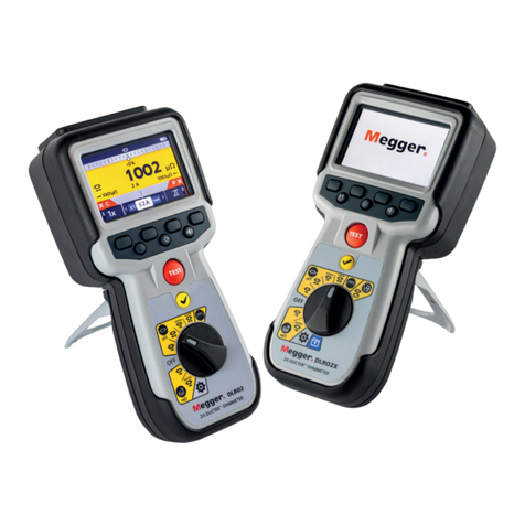
DLRO10HDX
10 A Digital Low Resistance Ohmmeter
APPLICATIONS
The DLRO10HDX measures low resistance values in applications
ranging from railways and aircraft to resistance of components
in industry.
Any metallic joint can be measured but users must be aware
of measurement limitations depending on application. For
example, if a cable manufacturer plans to make resistive
measurements on a thin wire, a low test current should be
selected to prevent heating the wire thereby changing its
resistance.
Measurements on electric motors and generators will
be inductive and require the user to understand the
inductive mode and charging process before a correct result
is achieved.
The DLRO10HDX is well suited to measuring thick conductors,
bonds and quality of welding because of its 10 A range for
resistance values up to 250 mΩ.
Electromagnetic noise induced into the leads can interfere
with a reading. A noise symbol alerts the user and prevents
a measurement when the instrument detects noise above its
threshold.
When dissimilar metals are joined a thermocouple effect is
created. Users should select a bidirectional mode to ensure
cancellation of this effect. The instrument measures with
current flowing in both directions and averages the result.
Normal mode is initiated by pressing the ‘Test’ button after
connecting the test leads to the unit under test. Continuity
of all four connections is checked. Current is applied in both
forward and reverse direction following which measurement
is displayed.
Automatic mode is started as soon as the probes make
contact. Forward and reverse current measurements are made
and the average value is displayed. This mode is ideal when
working with handspikes. Each time the probes are removed
and reconnected to the load a new test will be performed
without the need to press the test button.
TEST modes
Automatic unidirectional mode applies current in one
direction only to speed up the measurement process.
However thermal EMF resulting from dissimilar metal bonds
can cause lower accuracy. Test starts automatically when
probes are connected.
Continuous mode allows repeated measurements to be made
on the same sample. Simply connect the test leads and press
the test button. The measurement is updated every three
seconds until the circuit is broken.
Inductive mode is selected when measuring resistance on, for
example, motors and generators. When measuring inductive
loads it is necessary to wait for the voltage to stabilise as the
inductive element is charged. Test leads are firmly connected
to the device under test and the ‘Test’ button pressed. The
instrument will pass the selected current through the sample
continuously in one direction only and take repetitive readings
that will gradually decrease to the true value as the voltage
stabilises. The operator decides when the result is stable and
presses the ‘Test’ button to terminate the test.
ELECTRICAL SPECIFICATIONS
Resistance/Current Ranges
The green resistance ranges on the keypad indicate low
output power (<0.25 W) outputs. Red ranges indicate higher
2.5 W (1 A) and 25 W (10 A) power outputs.
Resolution and Accuracy
Test current accuracy ±10%
Voltmeter input impedance >200 kΩ
Maximum lead resistance at 10 A <100 mΩ
Test current
Resistance
range
Resolution (as
displayed)
Basic accuracy*
Full scale
voltage
Max. power
output
100 µA 0 - 2.5 kΩ 0.1 Ω ±0.2%
±200 mΩ 25 mV 25 μW
100 µA 0 - 250 Ω 0.01 Ω ±0.2%
±20 mΩ 25 mV 2.5 μW
1 mA 0 - 25 Ω 1 mΩ ±0.2%
±2 mΩ 25 mV 25 μW
10 mA 0 - 2.5 Ω 0.1 mΩ ±0.2%
±200 µΩ 25mV 250 μW
100 mA 0 - 250 mΩ 0.01 mΩ ±0.2%
±20 µΩ 25 mV 2.5 mW
1 A 0 - 25 mΩ 1 μΩ ±0.2%
±2 µΩ 25 mV 25 mW
10 A 0 - 2.5 mΩ 0.1 μΩ ±0.2%
±0.2 µΩ 25 mV 0.25 W
1 A ** 0 - 2.5 Ω 0.1 mΩ ±0.2%
±200 µΩ 2.5 V 2.5 W
10 A ** 0 - 250 mΩ 0.01 mΩ ±0.2%
±50 µΩ 2.5 V 25 W
* Basic accuracy stated assumes forward and reverse
measurements.
** Higher 2.5 W (1 A) and 25 W (10 A) power outputs.
Inductive mode or undirectional mode will introduce an
undefined error if an external EMF is present.
Basic accuracy at reference conditions.
