Megger MOM690 User manual

Art No. ZP-BB05E Doc. BB0220IE V06a 2019
WWW.MEGGER.COM
User’s Manual
MOM690
Micro-ohmmeter

Contents
1 Introduction
___________________________________ 4
2 Safety
___________________________________ 6
2.1 Symbols on the instrument ................................. 6
2.2 Safety instructions............................................... 6
3 Control panel
___________________________________ 8
3.1 Panel description................................................. 8
3.2 Display................................................................ 9
Menu options ...................................................... 9
Program version................................................... 9
4 Operating instructions
__________________________________ 10
4.1 Connection setup ............................................. 10
4.2 Operating ......................................................... 11
Safety functions................................................. 11
Measuring in AUTO mode ................................. 11
Measuring in MAN mode .................................. 11
Demagnetizing current transformer cores .......... 11
Calibration......................................................... 11
4.3 Application examples........................................ 12
Measuring resistance in a breaker ...................... 12
Measuring resistance at bus-bar joints................ 12
4.4 Software........................................................... 13
4.5 Troubleshooting................................................ 13
5 Specifications
__________________________________ 14
Specifications MOM690.......................................... 14
Cable sets – load currents ....................................... 15

MOM690
Micro-ohmmeter
NOTICE OF COPYRIGHT & PROPRIETARY RIGHTS
© 2010-2017, Megger Sweden AB. All rights reserved.
The contents of this manual are the property of Megger Sweden AB. No part of this work may be reproduced or transmitted in any form or
by any means, except as permitted in written license agreement with Megger Sweden AB. Megger Sweden AB has made every reasonable
attempt to ensure the completeness and accuracy of this document. However, the information contained in this manual is subject to change
without notice, and does not represent a commitment on the part of Megger Sweden AB. Any attached hardware schematics and technical
descriptions, or software listings that disclose source code, are for informational purposes only. Reproduction in whole or in part to create
working hardware or software for other than Megger Sweden AB products is strictly prohibited, except as permitted by written license
agreement with Megger Sweden AB.
TRADEMARK NOTICES
Megger® and Programma® are trademarks registered in the U.S. and other countries. All other brand and product names mentioned in this
document are trademarks or registered trademarks of their respective companies.
Megger Sweden AB is certified according to ISO 9001 and 14001.
User’s Manual
Postal address:
Megger Sweden AB
Box 724
SE-182 17 DANDERYD
SWEDEN
T +46 8 510 195 00
F +46 8 510 195 95
seinfo@megger.com
www.megger.com
Visiting address:
Megger Sweden AB
Rinkebyvägen 19
SE-182 36 DANDERYD
SWEDEN
BB0220IE ZP-BB05E MOM690 3

1Introduction
The MOM690 is designed to measure the resistances
of breaker contacts, bus-bar joints, contact elements
in bus-bars and other high-current links.
When contact resistance rises because of oxidation,
loosened or improperly tightened threaded joints,
temperatures rise abnormally at the points of contact.
This abnormal heating reduces conductivity thereby
accelerating the rise in temperature — and this often
leads to serious trouble.
The MOM690 can be used to detect such problems
early so that they can be remedied long before trouble
starts. Checking contact resistance at regular intervals
provides a clear indication of the state of your system.
During measurement, the instrument generates a high
current. This current must not cause excessive heating
inside the instrument. To prevent this, both a thermal
fuse and a miniature circuit breaker that serves as a
line fuse are provided. The instrument is equipped
with an induction protector. For protection against ex-
ternal overvoltages, both the current output and the
sensing input are decoupled to ground. A full-wave
rectified current, i.e. a pulsating DC current, is used
for measurement.
4MOM690 ZP-BB05E BB0220IE
1 INTRODUCTION

BB0220IE ZP-BB05E MOM690 5
2 SAFETY

2
Safety
2.1 Symbols on the
instrument
Caution, refer to accompanying docu-
ments.
Protective conductor terminal.
WEEE, Waste Electrical and Electronic
Equipment. Please utilize your local
WEEE collection facilities in the dispo-
sition of this product and otherwise
observe all applicable requirements.
The unit can also be returned to
Megger at any time at no charge for
the disposal.
Information duty regarding
substances on REACH article 33,
SVHC-list
This product contains a coin cell battery which con-
tains 1,2- dimethoxyethane (CAS 110-71-4) above
0.1% by weight.
2.2 Safety instructions
Important!
Read the manual and comply with the following
instructions before using the micro-ohmmeter.
Always comply with local safety regulations.
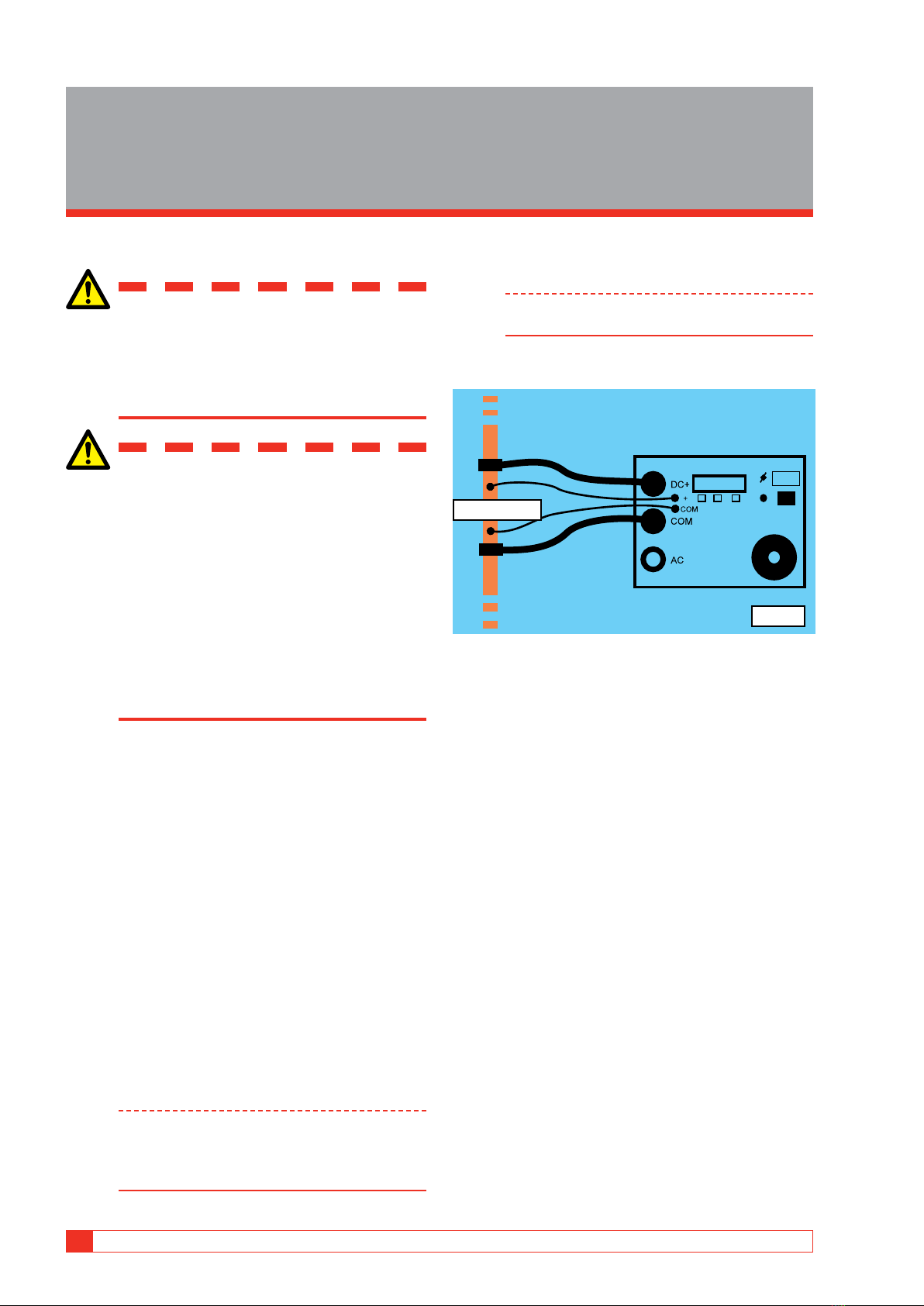
Warning
Before measuring resistances in circuit breakers or
disconnecting switches (isolators), always check
to see that the object being tested is closed and
grounded on one side.
If there is a current transformer in the current circuit,
the protective relay equipment that is connected
to it must be blocked to prevent actuation. After
completing your measurements, you can follow
the normal procedures that are used to demagnet-
ize current transformer cores after DC has passed
through their current transformer.
Never open a circuit breaker while a MOM690 is
connected to it.
The outputs DC+ and AC must not be loaded at the
same time.
Connection points for current cables can become
hot during current generation.
Current continues to flow for a while after the
MOM690 is turned off. How long it continues
depends on the ratio of the components in the L/R
circuit.
Important
Always connect protective earth (ground)
Always use safety connecting leads.
Always turn the equipment off before connecting.
High voltage/current on input/output terminals.
Never leave the instrument unattended while it is
turned on and in the highcurrent mode.
Unplug the instrument from the mains supply when
it is left unattended or not in use.
6MOM690 ZP-BB05E BB0220IE
2 SAFETY

Do not attempt to service the instrument yourself.
Opening or removing covers may expose you to
dangerous voltage. If you attempt to service the
instrument yourself the warranty is no longer valid.
Do not use any accessories that are not intended for
use together with the instrument.
Disconnect the instrument from the mains before
cleaning. Use a damp cloth for cleaning. Do not use
liquid cleaners or aerosol cleaners.
Use only approved mains detachable cable set with
the instrument. Main supply cables shall be rated for
the maximum current for the equipment and the ca-
ble shall meet the requirements of IEC 60227 or IEC
60245. Mains supply cables certified or approved by
a recognized testing authority are regarded as meet-
ing this requirement.
Refer all servicing to Megger authorized personnel.
If you need to return the instrument, please use ei-
ther the original crate or one of equivalent strength.
BB0220IE ZP-BB05E MOM690 7
2 SAFETY

3Control panel
3.1 Panel description
1. Grounding terminal
2. Connection for mains voltage
3. Miniature circuit breaker for mains
4. Switch for mains voltage
5. Variable transformer
6. AC current output (–)
7. AC/DC current output
8. DC current output (+)
9. Sensing terminal
10. Display
11. Scrolling key for the display
12. Function selector
13. Interrupts current and toggles the display
between resistance and voltage
14. Serial interface for PC (RS 232)
⓭
4
3
2
5
6
7
❿
9
⓫
8
⓬
1
⓮
8MOM690 ZP-BB05E BB0220IE
3 CONTROL PANEL

3.2 Display
Indicates whether the cur-
rent is above (>) or below
(<) a preselected value.
Value of the generated
current.
Information about
current generation or
memory location.
Shows the measured resistance
or voltage value. Toggle by
pressing the <Ω>-key.
Selected function. Scroll
using the <FUNC>-key.
Selected test current for
"Auto"/"DC Off"
Scroll using the <▲>-key.
>A 123A DC On
100A AUTO 100µΩ
Menu options
You can make different settings with the keys beneath
the display.
Select language
>A 118A DC On
100A AUTO 63µΩ
1] Press the <FUNC>-key to enter the "AUTO"
or "MAN"mode.
2] While holding down the <▲>-key, press the
<FUNC>-key.
Select language
ENGLISH OK
3] Use the <▲>-key to scroll to the desired lan-
guage.
4] Finish by pressing the <W>-key.
Save test results
Record Mem1-30
On REC Save
The memory function is turned on or off using the
<▲>-key. When you take measurements in the
"MAN" or "AUTO" mode, the values measured are
stored in the memory.
>A 123A Rec>1
100A AUTO 67µΩ
Memory locations are filled successively until all 30 are
full, whereupon the next measured value replaces the
oldest of those already in the memory.
100A Mem-8
View PLAY 57µΩ
To view the values stored in memory, scroll to "PLAY"
using the <FUNC>-key. Then step forward in the
memory by pressing the <▲>-key (hold the key down
to step faster). Press the <Ω>-key to view the voltage
value, and press it a second time to view the resist-
ance value.
Note Values stored in memory vanish when you
turn of the MOM690.
Save values permanently
1] To save the values permanently, you scroll to
the "REC" position using the <FUNC>-key.
2] Then press the <Ω>-key, whereupon the val-
ues will be saved.
Saving Mem1-30..
Reset all values in the memory
1] Step to "AUTO" or "MAN" using the
<FUNC>-key.
2] While holding down the <▲>-key, press the
<Ω>-key.
3] Press the <FUNC> key to reply “Yes”.
Program version
To view the program version, first press the <FUNC>-
key and then, while holding it down, press the <Ω>-
key.
BB0220IE ZP-BB05E MOM690 9
3 CONTROL PANEL

4Operating instructions
4.1 Connection setup
Important
Read the manual and comply with the
Safety instructions, see page 6, before
using the micromhmeter.
Always comply with local safety regula-
tions.
Warning
If there is a current transformer in the
current circuit, the protective relay equip-
ment that is connected to it must be
blocked to prevent actuation.
If you are measuring resistance in a circuit
breaker or disconnecting switch (isolator),
make sure that it is closed before starting.
High current must only flow throughout a
short interval. Never leave the instrument
unattended while it is turned on and in
the high-current mode.
1] Make certain the mains are de-energized on
both sides of the breaker. Ground the break-
er on one side and make certain it is closed.
2] Keep the MOM690 disconnected from the
mains while making connections.
3] Ground the MOM690.
4] Connect one current cable between one
side of the object being tested and the DC+
terminal on the MOM690. Connect the other
current cable between the other side of the
object being tested and the COM- terminal
on the MOM690.
5] Connect the two sensing cables (using the
same polarities as those used for the current
cables) on two sides of the test object and as
close to the test object as possible.
Important:
The sensing cables must be connected inside
the current cables. Otherwise the test data
may be incorrect. See Fig.1.
6] Connect the MOM690 to the mains and
switch it on.
Note Since power consumption is high, the instru-
ment requires a 16 A fuse.
7] Select "AUTO" or "MAN" with the <FUNC>-
key.
Test object
Fig. 1
10 MOM690 ZP-BB05E BB0220IE
4 OPERATING INSTRUCTIONS

4.2 Operating
Safety functions
Timed current cut-off
Current from the instrument is interrupted automati-
cally after a certain interval whose length depends on
the value of the current. Repeated short beeps are
heard before the current is interrupted. When you
hear them, you should reduce the current or press the
<Ω>-key. "O.L.!" will appear on the display.
O.L.! 420A DC On
MAN 63µΩ
High temperature
If the temperature in the instrument rises too high, re-
peated short beeps are heard, and the display shows:
! OVERHEATED
Please wait...
The temperature must drop before you can continue.
Measuring in AUTO mode
1] Select the desired current using the <▲>-key.
2] Turn the knob on the variable transformer
down to 0, whereupon it will enter the
current-generation mode.
3] Turn the knob on the variable transformer
to the right. When the current reaches the
preslected value, ="A" appears on the dis-
play and a long beep is heard. The current
is interrupted. The display shows the word
"Off" and the values are frozen.
Note When the current is lower or higher than the
preselected value, "< A" or "> A" respectively
appears on the display. When the current
exceeds (passes) the preselected measurement
current a short beep is heard.
4] Turn off and disconnect the MOM690 from
the mains before doing any disconnection
work or moving any cables or wiring.
Measuring in MAN mode
1] Turn the knob on the variable transformer
down to "0", whereupon it will enter the
current-generation mode.
2] Now turn the knob on the variable trans-
former to the right until the current rises to
the desired value.
3] Press the <W>-key, the instrument will cut off
the current and hold the measured values.
4] Turn off and disconnect the MOM690 from
the mains before doing any disconnection
work or moving any cables or wiring.
Demagnetizing current
transformer cores
It is important to demagnetize current transformer
cores after DC has passed through the current trans-
former.
1] After measurement is finished, connect the
DC current cable to the AC output.
2] Select the "AC" function using the <FUNC>-
key.
<10% 0A Off
129A AC
3] The highest frozen current value appears at the
bottom of the left side of the display.
4] Increase the current until "< 10%", shown at
top left on the display, changes to "> 10%".
A long beep will be heard simultaneously,
and the frozen current value will be erased
from the memory.
5] Decrease the current down to zero.
Calibration
An external calibration shunt (600 A/60 mV) is avail-
able as an accessory. Art.No: BB-90024
BB0220IE ZP-BB05E MOM690 11
4 OPERATING INSTRUCTIONS

4.3 Application examples
Measuring resistance in a breaker
Important
Read the manual and comply with the
Safety instructions, see page 6, before
using the micromhmeter.
Always comply with local safety regula-
tions.
Fig. 2
1] Make certain the mains are de-energized on
both sides of the breaker. Ground the break-
er on one side and make certain it is closed.
2] Keep the MOM690 disconnected from the
mains while making connections.
3] Ground the MOM690.
4] Connect the current cables and the sensing
cables (with the same polarities) on both
sides of the breaker. The sensing cables
must be connected inside the current cables.
Otherwise the test data may be incorrect. See
fig. 2.
5] Connect the MOM690 to the mains.
6] Switch on the MOM690.
7] Select "AUTO" or "MAN" with the <FUNC>-
key.
8] See also the sections headed "Measuring
in MAN mode" and "Measuring in AUTO
mode".
9] Turn off and disconnect the MOM690 from
the mains before doing any disconnection
work or moving any cables or wiring.
Measuring resistance at bus-bar
joints
Important
Read the manual and comply with the
Safety instructions, see page 6, before
using the micromhmeter.
Always comply with local safety regula-
tions.
Fig. 3
1] Make certain the mains are de-energized on
both sides of the bus-bar. Ground the bus-bar
on one side.
2] Keep the MOM690 disconnected from the
mains while making connections.
3] Ground the MOM690.
4] Connect the MOM690’s current cables to
the test object. Do not connect the sensing
cables. Measurement will be done manually
using an external portable voltmeter.
5] Connect the MOM690 to the mains.
6] Switch on the MOM690.
7] Select "MAN" with the <FUNC>-key.
8] Turn down the knob on the variable trans-
former to 0.
9] Increase the current to the desired value.
10] Using an external voltmeter, measure the
voltage drop (voltage) across each contact
element within every section of the bus-bar
being tested. The multimeter must be set to
DC and to measure voltage.
11] Calculate the actual resistance yourself.
Example: If the voltage drop is 0.0067 V at
a current of 100 A, the resistance will be
0.0067/100 ohms, i.e. 67 microhms.
12] Turn off and disconnect the MOM690 from
the mains before doing any disconnection
work or moving any cables or wiring.
12 MOM690 ZP-BB05E BB0220IE
4 OPERATING INSTRUCTIONS

4.4 Software
A PC program is available as an accessory. The PC is
connected via the serial port on the MOM690. Us-
ing a Windows program named MOMWin, you can
conduct further analyses and prepare reports of the
results. The MOM690 can be controlled from a PC
during measurement, but the user can also retrieve
previously stored measurement results for analysis. All
measured values are saved in ASCII format and can be
exported easily to your favorite spreadsheet program
(not included with MOMWin). Results can be present-
ed graphically or in table form in MOMWin.
4.5 Troubleshooting
Fault Cause Remedy
The display pre-
sents O.L.
The measuring
range of the
instrument has
been exceeded.
If possible, select
a different cur-
rent range.
Poor contact at
measurement
cables.
Check the con-
nections.
Thermal miniature
circuit breaker
has tripped.
Overload. Wait for the in-
strument to cool
down.
Miniature circuit
breaker that
serves as a line
fuse has tripped.
Overload or faulty
instrument.
Reset the
miniature circuit
breaker. If it trips
again, contact
service personnel.
BB0220IE ZP-BB05E MOM690 13
4 OPERATING INSTRUCTIONS

5Specifications
Specifications MOM690
Specifications are valid at nominal input voltage and an ambient
temperature of +25°C, (77°F). Specifications are subject to change
without notice.
Environment
Application field The instrument is intended for use in
high-voltage substations and industrial
environments.
Temperature
Operating 0°C to +50°C (32°F to +122°F)
Storage & transport -40°C to +70°C (-40°F to +158°F)
Humidity 5% – 95% RH, non-condensing
CE-marking
LVD 2014/35/EU
EMC 2014/30/EU
RoHS 2 011/ 65 / EU
General
Mains voltage 115 / 230 V AC, 50 / 60 Hz
Power consumption
(max)
115 V, 5980 VA (at 600 A output)
230 V, 9660 VA
Protection Miniature circuit breaker, thermal fuse,
software
Dimensions
Instrument 350 x 270 x 220 mm
(13.8” x 10.6” x 8.7”)
Transport case 610 x 290 x 360 mm
(24.0” x 11.4” x 14.2”)
Weight, 115 V model 24 kg (52.9 lbs)
38.9 kg (85.7 lbs) with accessories and
transport case
Weight, 230 V model 23.7 kg (52.2 lbs)
38.6 kg (85.1 lbs) with accessories and
transport case
Available languages English, French, German, Spanish,
Swedish
Current cables 2 x 5 m (16 ft), 50 mm²
Sensing cables 2 x 5 m (16 ft), 2.5 mm²
Optional current cable sets
Ext.1 Extension 2 x 5 m, 50 mm²
Ext.2 Extension 2 x 10 m, 50 mm²
2 x 15 m (49.2 ft) 95 mm²
Measurement section
Ammeter
Range 0 – 800 A
Resolution 1 A
Inaccuracy 100 – 800 A, ±1% of reading + 1 digit
50 – 99 A, ±(2% of reading + 2 digits)
0 – 49 A, not specified
Resistance
Range 0 – 200 mΩ, > 200 mΩ not specified
Resolution 1 μΩ
Inaccuracy 100 – 800 A, ±1% of reading + 1 digit
50 – 99 A, ±(2% of reading + 2 digits)
0 – 49 A, not specified
Max. load resistance / current, 115 V model
Cable set Standard Standard
+ Ext. 1
Standard
+ Ext. 2
2 x 15 m
95 mm²
At 300 A 10 mΩ 6 mΩ 3 mΩ 10 mΩ
Max. cur-
rent 575 A 420 A 360 A 540 A
Max. load resistance / current, 230 V model
Cable set Standard Stadard +
Ext. 1
Stadard
+ Ext. 2
2 x 15 m
95 mm²
At 300 A 18 mΩ 14 mΩ 11 mΩ 18 mΩ
At 600 A 3.0 mΩ 1.8 mΩ
Max. cur-
rent 750 A 570 A 480 A 690 A
Output DC (CAT I), 115 V model
Current (A) Voltage (V) Max. load time Input cur-
rent (A)
0 7.3 –0.8
50 6.9 30 min.
100 6.4 10 min. 10
200 5.5 60 s 19
300 4.8 35 s
400 3.9 20 s 38
500 3.0 10 s
5751) 2.5 2 s
600 2.2 0.5 s 52
700 1.5 0.2 s
8002) 0.9 –
1) Maximum current with standard cables 2 x 5 m 50 mm²
2) At 800 A and above, instant shut off
Note: The above figures shows maximum load time from cold state 25°C. They are not
valid for repeated tests
Output AC (CAT I), 115 V model
Current (A) Voltage (V) Max. load time Rest time
08.7 Cont. –
660 3.5 2 s 4 min.
Note: The DC and AC outputs must not be loaded at the same time.
Output DC (CAT I), 230 V model
Current (A) Voltage (V ) Max. load time Input cur-
rent (A)
0 9.4 –0.4
50 9.0 30 min.
100 8.6 10 min. 6
200 8.0 90 s
300 7. 2 30 s
400 6.4 20 s
500 5.7 10 s
600 5.0 5 s 33
700 4.3 3 s
7501) 3.8 1 s
8002) 3.6 –42
1) Maximum current with standard cables 2 x 5 m 50 mm²
2) At 800 A and above, instant shut off
Note: The above figures shows maximum load time from cold state 25°C. They are not
valid for repeated tests
Output AC (CAT I), 230 V model
Current
(A)
Voltage
(V AC)
Max. load time Rest time
011.2 Cont. –
660 4.5 2 s 4 min.
Note: The DC and AC outputs must not be loaded at the same time.
14 MOM690 ZP-BB05E BB0220IE
5 SPECIFICATIONS

Cable sets – load currents
Cable set
Standard
2 x 5 m,
(16.4 ft)
50 mm2
Standard
+ Ext. 1
Standard
+ Ext. 2
2 x 15 m
(49.2 ft)
95 mm2
Maximal
current at
100 µΩ
750 A(1
575 A(2
570 A(1
420 A(2
480 A(1
360 A(2
690 A(1
540 A(2
Max. load
at 300 A
18 m(1
10 m(2
14 m(1
6 m(2
11 m(1
3 m(2
18 m(1
10 m(2
Max. load
at 600 A
3.0 m(1 _ _ 1.8 m(1
(1 MOM 690 for 230 V (2 MOM 690 for 115 V
Ext. 1 = 2 x 5 m (16.4 ft)
50 mm2
Ext. 2 = 2 x 10 m (32.8 ft)
50 mm2
BB0220IE ZP-BB05E MOM690 15
5 SPECIFICATIONS

WWW.MEGGER.COM
Your “One Stop” Source for all your electrical test equipment needs
Megger is a leading global manufacturer and supplier
of test and measurement instruments used within the
electric power, building wiring and telecommunication
industries.
With research, engineering and manufacturing facilities
in the USA, UK, Germany and Sweden, combined with
sales and technical support in most countries, Megger
is uniquely placed to meet the needs of its customers
worldwide.
Megger is certified according to ISO 9001 and 14001.
Megger is a registered trademark.
Postal address:
Megger Sweden AB
Box 724
SE-182 17 DANDERYD
SWEDEN
T +46 8 510 195 00
F +46 8 510 195 95
seinfo@megger.com
www.megger.com
Visiting address:
Megger Sweden AB
Rinkebyvägen 19
SE-182 36 DANDERYD
SWEDEN
▪Battery Test Equipment
▪Cable Fault Locating Equipment
▪Circuit Breaker Test Equipment
▪Data Communications Test Equipment
▪Fiber Optic Test Equipment
▪Ground Resistance Test Equipment
▪Insulation Power Factor (C&DF) Test Equipment
▪Insulation Resistance Test Equipment
▪Line Testing Equipment
▪Low Resistance Ohmmeters
▪Motor & Phase Rotation Test Equipment
▪Multimeters
▪Oil Test Equipment
▪Portable Appliance & Tool Testers
▪Power Quality Instruments
▪Recloser Test Equipment
▪Relay Test Equipment
▪T1 Network Test Equipment
▪Tachometers & Speed Measuring Instruments
▪TDR Test Equipment
▪Transformer Test Equipment
▪Transmission Impairment Test Equipment
▪Watthour Meter Test Equipment
▪STATES® Terminal Blocks & Test Switches
▪Professional Hands-On Technical and
Safety Training Programs
▪AUSTRALIA
▪BULGARIA
▪CANADA
▪CZECH REPUBLIC
▪CHINA
▪FRANCE
▪GERMANY
▪HUNGARY
▪INDIA
▪INDONESIA
▪KINGDOM OF BAHRAIN
▪KOREA
▪MALAYSIA
▪PAKISTAN
▪PHILIPPINES
▪POLAND
▪ROMANIA
▪RUSSIA
▪SINGAPORE
▪SLOVAK REPUBLIC
▪SOUTH AFRICA
▪SPAIN
▪SWEDEN
▪SWITZERLAND
▪TAIWAN
▪THAILAND
▪UNITED ARAB EMIRATES
▪USA
▪VIETNAM
Megger Group Limited
UNITED KINGDOM
Dover, Kent CT17 9EN
ENGLAND
Subject to change without notice. Printed matter No. ZP-BB05E Doc. BB0220IE V06a 2019
Table of contents
Other Megger Measuring Instrument manuals

Megger
Megger MOM200A User manual

Megger
Megger PVM210 User manual

Megger
Megger 1006-603 User manual

Megger
Megger frax 99 User manual

Megger
Megger TM1700 Series User manual

Megger
Megger TTRU3 User manual

Megger
Megger DLRO 200 User manual

Megger
Megger Three-Phase TTR User manual

Megger
Megger DCM300E User manual

Megger
Megger DPM1000 User manual

Megger
Megger MWA300 Series User manual

Megger
Megger HV DAC-200 User manual

Megger
Megger Baker DX User manual

Megger
Megger DCM330 User manual

Megger
Megger Power Diagnostix ICMflex User manual

Megger
Megger DCM340 User manual

Megger
Megger HVB 10 User manual

Megger
Megger ATEC 210415 Series User manual

Megger
Megger MPQ1000 User manual

Megger
Megger MTO106 User manual