ST STEVAL-IDZ3V1 Series User manual

December 2011 Doc ID 022085 Rev 2 1/28
UM1454
User manual
STEVAL-IDZ3xxV1 demonstration kit for the SPZB32W1x2.x
series of 802.15.4/ZigBee® radio communication modules
Introduction
The STEVAL-IDZ3xxV1 is a demonstration kit from the SPZB32W1x2.x series of
802.15.4/ZigBee®RF modules based on the STM32W108CB microcontroller that integrates
a 32-bit ARM®Cortex™ M3 microprocessor and a 2.4 GHz, IEEE 802.15.4 radio.
Accordingly, with the loaded protocol stack and application SW, the STM32W108CB
microcontroller is suitable for different types of wireless network scenarios.
Each STEVAL-IDZ3xxV1 kit enables the user to test the RF module performances, the
features of the protocol libraries defined for the microcontroller, and to prototype the target
802.15.4/ZigBee application. The kit includes a development board and a software library
that can be integrated into the structure of the packages available from the ST website for
the use of ZigBee PRO, Zigbee RF4CE and simplified MAC on the STM32W108CB
microcontroller. The STEVAL-IDZ3xxV HW integrates an RF module belonging to the
SPZB32W1x2.x series together with an extended number of external connectors that allow
the integration of peripherals as requested by the target application.
The STEVAL-IDZ3xxV1 kit can be used for the following purposes.
■Demonstration: ZigBee PRO. By using the sensor/sink application example integrated in
the kit and two development boards, the user can easily set up a demo showing a few of
the basic features of the ZigBee protocol stack.
■Development: by using external equipment consisting of a development environment for
the STM32W, the kit can be used to prototype and debug a target application.
This document describes the hardware and software components of the STEVAL-IDZ3xxV1
and provides instructions for setting up the hardware and loading and running the
application examples. This document is not meant to be a ZigBee tutorial and assumes that
the user is familiar with IAR development tools and the basic features of the STM32W108CB
microprocessor.
Figure 1. STEVAL-IDZ301V1
www.st.com
www.BDTIC.com/ST

Contents UM1454
2/28 Doc ID 022085 Rev 2
Contents
1 Kit parts . . . . . . . . . . . . . . . . . . . . . . . . . . . . . . . . . . . . . . . . . . . . . . . . . . . 6
1.1 Hardware . . . . . . . . . . . . . . . . . . . . . . . . . . . . . . . . . . . . . . . . . . . . . . . . . . 6
1.2 Software . . . . . . . . . . . . . . . . . . . . . . . . . . . . . . . . . . . . . . . . . . . . . . . . . . . 7
1.3 CD . . . . . . . . . . . . . . . . . . . . . . . . . . . . . . . . . . . . . . . . . . . . . . . . . . . . . . . 7
1.4 External equipment . . . . . . . . . . . . . . . . . . . . . . . . . . . . . . . . . . . . . . . . . . 7
1.4.1 IAR toolset . . . . . . . . . . . . . . . . . . . . . . . . . . . . . . . . . . . . . . . . . . . . . . . . 7
1.5 HW and SW compatibility . . . . . . . . . . . . . . . . . . . . . . . . . . . . . . . . . . . . . . 8
2 HW description . . . . . . . . . . . . . . . . . . . . . . . . . . . . . . . . . . . . . . . . . . . . . 9
2.1 STEVAL description . . . . . . . . . . . . . . . . . . . . . . . . . . . . . . . . . . . . . . . . . . 9
2.2 Recommended operating conditions . . . . . . . . . . . . . . . . . . . . . . . . . . . . 10
2.3 Board connections . . . . . . . . . . . . . . . . . . . . . . . . . . . . . . . . . . . . . . . . . . 11
2.4 STEVAL layout . . . . . . . . . . . . . . . . . . . . . . . . . . . . . . . . . . . . . . . . . . . . . 13
2.5 HW general features . . . . . . . . . . . . . . . . . . . . . . . . . . . . . . . . . . . . . . . . 14
2.5.1 I/O signal voltage configuration . . . . . . . . . . . . . . . . . . . . . . . . . . . . . . . 14
2.5.2 Reset . . . . . . . . . . . . . . . . . . . . . . . . . . . . . . . . . . . . . . . . . . . . . . . . . . . 14
2.5.3 Configurable button . . . . . . . . . . . . . . . . . . . . . . . . . . . . . . . . . . . . . . . . 14
2.5.4 Voltage battery meter . . . . . . . . . . . . . . . . . . . . . . . . . . . . . . . . . . . . . . . 14
2.5.5 Temperature sensor . . . . . . . . . . . . . . . . . . . . . . . . . . . . . . . . . . . . . . . . 15
2.5.6 Ground points . . . . . . . . . . . . . . . . . . . . . . . . . . . . . . . . . . . . . . . . . . . . 15
2.5.7 Test points . . . . . . . . . . . . . . . . . . . . . . . . . . . . . . . . . . . . . . . . . . . . . . . 15
2.5.8 Setting up STEVAL . . . . . . . . . . . . . . . . . . . . . . . . . . . . . . . . . . . . . . . . 16
2.5.9 Powering setup . . . . . . . . . . . . . . . . . . . . . . . . . . . . . . . . . . . . . . . . . . . 16
2.5.10 Serial communication interface setup . . . . . . . . . . . . . . . . . . . . . . . . . . 17
2.5.11 Boot mode setup . . . . . . . . . . . . . . . . . . . . . . . . . . . . . . . . . . . . . . . . . . 17
2.6 Getting started with the kit . . . . . . . . . . . . . . . . . . . . . . . . . . . . . . . . . . . . 18
2.6.1 Installing the IDZ3LIB library . . . . . . . . . . . . . . . . . . . . . . . . . . . . . . . . . 18
2.6.2 IDZ3LIB content . . . . . . . . . . . . . . . . . . . . . . . . . . . . . . . . . . . . . . . . . . . 18
2.6.3 Integration of IDZ3LIB in EmberZnet 4.0.2 . . . . . . . . . . . . . . . . . . . . . . 18
2.6.4 Integration of IDZ3LIB in EmberZnet 4.3.0 package library . . . . . . . . . . 18
2.6.5 Install the CP2102 drivers . . . . . . . . . . . . . . . . . . . . . . . . . . . . . . . . . . . 19
2.6.6 Install and run the Flash loader demonstrator tool . . . . . . . . . . . . . . . . 19

www.BDTIC.com/ST

UM1454 Contents
Doc ID 022085 Rev 2 3/28
3 Install and run the sink-sensor application . . . . . . . . . . . . . . . . . . . . . 21
3.1 Sink-sensor sample application . . . . . . . . . . . . . . . . . . . . . . . . . . . . . . . . 21
3.2 Load sink-sensor on the STEVAL . . . . . . . . . . . . . . . . . . . . . . . . . . . . . . 22
3.3 Setting-up a network and running the sink-sensor application . . . . . . . . . 22
4 RoHS compliance . . . . . . . . . . . . . . . . . . . . . . . . . . . . . . . . . . . . . . . . . . 25
Appendix A STEVAL electrical schematic . . . . . . . . . . . . . . . . . . . . . . . . . . . . . . 26
Revision history . . . . . . . . . . . . . . . . . . . . . . . . . . . . . . . . . . . . . . . . . . . . . . . . . . . . 27
www.BDTIC.com/ST

List of tables UM1454
4/28 Doc ID 022085 Rev 2
List of tables
Table 1. The STEVAL-IDZ3xxV1 versions . . . . . . . . . . . . . . . . . . . . . . . . . . . . . . . . . . . . . . . . . . . . . 6
Table 2. Abbreviations . . . . . . . . . . . . . . . . . . . . . . . . . . . . . . . . . . . . . . . . . . . . . . . . . . . . . . . . . . . . 6
Table 3. Recommended operating conditions . . . . . . . . . . . . . . . . . . . . . . . . . . . . . . . . . . . . . . . . . 10
Table 4. Board connections and configuration . . . . . . . . . . . . . . . . . . . . . . . . . . . . . . . . . . . . . . . . . 11
Table 5. STEVAL interfaces maximum voltage configuration. . . . . . . . . . . . . . . . . . . . . . . . . . . . . . 14
Table 6. Document revision history . . . . . . . . . . . . . . . . . . . . . . . . . . . . . . . . . . . . . . . . . . . . . . . . . 27
www.BDTIC.com/ST

UM1454 List of figures
Doc ID 022085 Rev 2 5/28
List of figures
Figure 1. STEVAL-IDZ301V1. . . . . . . . . . . . . . . . . . . . . . . . . . . . . . . . . . . . . . . . . . . . . . . . . . . . . . . . 1
Figure 2. STEVAL block diagram. . . . . . . . . . . . . . . . . . . . . . . . . . . . . . . . . . . . . . . . . . . . . . . . . . . . . 9
Figure 3. STEVAL image and main components. . . . . . . . . . . . . . . . . . . . . . . . . . . . . . . . . . . . . . . . . 9
Figure 4. STEVAL layout . . . . . . . . . . . . . . . . . . . . . . . . . . . . . . . . . . . . . . . . . . . . . . . . . . . . . . . . . . 13
Figure 5. STEVAL mechanical dimensions (mm) . . . . . . . . . . . . . . . . . . . . . . . . . . . . . . . . . . . . . . . 13
Figure 6. Ground points for daughterboard connection . . . . . . . . . . . . . . . . . . . . . . . . . . . . . . . . . . . 15
Figure 7. Test points for RCM power measuring . . . . . . . . . . . . . . . . . . . . . . . . . . . . . . . . . . . . . . . . 15
Figure 8. Jumper positioning . . . . . . . . . . . . . . . . . . . . . . . . . . . . . . . . . . . . . . . . . . . . . . . . . . . . . . . 16
Figure 9. External power supply JP conf. . . . . . . . . . . . . . . . . . . . . . . . . . . . . . . . . . . . . . . . . . . . . . 16
Figure 10. Mini-USB power supply JP conf. . . . . . . . . . . . . . . . . . . . . . . . . . . . . . . . . . . . . . . . . . . . . 16
Figure 11. Mini-USB connection JP conf. . . . . . . . . . . . . . . . . . . . . . . . . . . . . . . . . . . . . . . . . . . . . . . 17
Figure 12. RS-232 connection JP conf. . . . . . . . . . . . . . . . . . . . . . . . . . . . . . . . . . . . . . . . . . . . . . . . . 17
Figure 13. Boot JP conf. . . . . . . . . . . . . . . . . . . . . . . . . . . . . . . . . . . . . . . . . . . . . . . . . . . . . . . . . . . . 17
Figure 14. Disabled boot JP conf. . . . . . . . . . . . . . . . . . . . . . . . . . . . . . . . . . . . . . . . . . . . . . . . . . . . . 17
Figure 15. COM associated to USB-to-UART bridge. . . . . . . . . . . . . . . . . . . . . . . . . . . . . . . . . . . . . . 19
Figure 16. stm32w-flasher command syntax . . . . . . . . . . . . . . . . . . . . . . . . . . . . . . . . . . . . . . . . . . . . 20
Figure 17. Sink advertise and form network messages . . . . . . . . . . . . . . . . . . . . . . . . . . . . . . . . . . . . 23
Figure 18. Sink: join and data messages . . . . . . . . . . . . . . . . . . . . . . . . . . . . . . . . . . . . . . . . . . . . . . . 23
Figure 19. Sensor: join and data messages . . . . . . . . . . . . . . . . . . . . . . . . . . . . . . . . . . . . . . . . . . . . 24
Figure 20. Sink: “i” command output . . . . . . . . . . . . . . . . . . . . . . . . . . . . . . . . . . . . . . . . . . . . . . . . . . 24
Figure 21. Schematic . . . . . . . . . . . . . . . . . . . . . . . . . . . . . . . . . . . . . . . . . . . . . . . . . . . . . . . . . . . . . . 26
www.BDTIC.com/ST

Kit parts UM1454
6/28 Doc ID 022085 Rev 2
1 Kit parts
As specified in Ta b le 1 , several versions of the STEVAL-IDZ301V1 and STEVAL-IDZ302V1
are defined based on the SPZB32W1x2.x module type that is integrated.
The following abbreviations are used throughout this document.
The kit consists of the parts described in the following sections.
1.1 Hardware
Fully featured development board that targets the prototyping of network devices. External
connectors allow to integrate the peripherals as desired. The board can be supplied by
means of an external +5 V supply or through the integrated mini-USB connector.
STEVAL integrates the following:
●An RF module belonging to the series of ZigBee/802.15.4 SPZB32W1x2.x modules
●A 20-pin JTAG connector for programming and debugging purposes
●Hardware support for application development:
– Temperature sensor
– Voltage battery measure circuitry
– Two configurable pushbuttons
– Two configurable LEDs
●Mini-USB connector and USB-RS-232 bridge
●A reset pushbutton
●A DC power source selection between the external power supply or external USB
supply
Table 1. The STEVAL-IDZ3xxV1 versions
Order codes Integrated module
STEVAL-IDZ301V1 SPZB32W1A2
STEVAL-IDZ302V1 SPZB32W1C2
Table 2. Abbreviations
Full name Abbreviation
STEVAL-IDZ3xxV1 The kit
STEVAL-IDZ3xxV1 HW STEVAL
STEVAL-IDZ3xxV1 SW IDZ3LIB
Radio communication module RCM
SPZB32W1xx RCM
STM32W108CB STM32W
www.BDTIC.com/ST

UM1454 Kit parts
Doc ID 022085 Rev 2 7/28
●Power indicator LED
●A jumper for boot activation
●Jumpers for serial communication setup (RS232 or mini-USB)
●24-pin double-row header for access to the remaining STM32W GPIO signals and
interfaces.
1.2 Software
The kit contains a software package including application samples and utilities for using the
STEVAL.
1.3 CD
The kit includes a CD that contains the software and documentation for use of the kit. A
datasheet, application notes, and user guides for use of STM32W, and an IAR tools suite
can be found at the ST and IAR websites respectively.
1.4 External equipment
The following minimum external equipment is required to use the kit functions:
●A PC with Windows XP®
●A mini-USB cable to connect the board with the PC via the mini-USB interface
●The IAR toolset to debug and reprogram the STM32W micro
●An IAR J-Link or an ST-Link in-circuit debugger/programming
●The kit is compatible with the tools, IAR and Perytons supported by the STM32W-SK kit
for STM32W108xx. See related documentation for details.
1.4.1 IAR toolset
The IAR embedded Workbench IDE for ARM is a very powerful integrated development
environment used for developing and managing complete embedded application projects.
Note: For programming (and/or debugging) using the IAR toolset, an IAR J-Link JTAG emulator is
required. The IAR J-LINK is a JTAG emulator designed for ARM cores. It connects via a
USB port to a PC running Windows 2000 or XP. It has a built-in 20-pin JTAG connector,
which is compatible with the standard 20-pin connector defined by ARM. When using the
IAR J-Link, an external power supply is required to power the STEVAL board. The first time
the IAR J-Link is plugged into the PC's USB port, the user is requested to provide the
relative J-Link driver. To do this, browse to the IAR installation directory and select the folder
ARM > Driver > J-Link. The IAR toolset and the IAR J-Link are not provided with the kit. For
detailed information and documentation about IAR products, refer to www.iar.com. As an
alternative, ST-Link can be used in place of the IAR J-Link emulator. ST-Link is a very low-
cost, in-circuit debugger/programmer for STM32. It connects to the application or
demonstration board for programming and debugging via a JTAG std connection. The
complete ST-Link documentation is available from www.st.com.
www.BDTIC.com/ST

8/28 Doc ID 022085 Rev 2
1.5 HW and SW compatibility
The STEVAL-IDZ301V1 and STEVAL-IDZ302V1 have been successfully tested with the
following libraries and ToolSuite versions:
EmberZnet package, versions 4.0.2. and 4.3.0
STM32W_flasher.1.1.0 available on the CD of the kit
Sink-Sensor example. Included in the kit
IAR version 5.41.2
CP2102 driver. Available at www.silabs.com and also included in the CD of the kit.
www.BDTIC.com/ST

UM1454 HW description
Doc ID 022085 Rev 2 9/28
2 HW description
2.1 STEVAL description
Figure 2. STEVAL block diagram
Figure 3. STEVAL image and main components
!-V
"ATTERY0OWER *ACK6 MINI53"6
0OWER 3UPPLY 3ELECTOR
*UMPER
3UPPLY MAIN
VOLTAGE REGULATOR
*4!'
30:"7X
34-
4EMPERATURESENSOR
*4!'
#ONNECTOR
2ESET0USH
"UTTON ,%$3
0USH"UTTONS
)-$!
5!24
'0)/
%XTCONNECTOR
*UMPER FOR
3ERIAL"OOT
53"5!24
"RIDGE
3ERIAL3ELECTOR
*UMPER
MINI53" 3ERIAL
AM09416v1
STLM75 Reset
Conf. buttonsPowerLed
P
Jk
Conf.
Leds
IMD9A
P
ower
J
ac
k
P
Boot
Jmp
MiniUSB
P
ower
JMP
RS232/USB
Bridge
Bridge
SPZB32W1xx
JTAG Connector
24 pin Exp.
Connector
Serial
JMP
www.BDTIC.com/ST

HW description UM1454
10/28 Doc ID 022085 Rev 2
2.2 Recommended operating conditions
Table 3. Recommended operating conditions
Symbol Parameter Conditions Min. Typ. Max. Unit
J1- Ext.VIN Main board supply voltage -20 °C < T < 70 °C 4 5 6 V
J2- Ext.VIN Alternate board (ext. battery)
supply voltage -10 °C < T < 60 °C 4 5 6 V
Tamb Operating ambient temperature -20 +70 °C
www.BDTIC.com/ST

UM1454 HW description
Doc ID 022085 Rev 2 11/28
2.3 Board connections
Table 4. Board connections and configuration
Description
J1 (2 poles) Ext. VIN (typ. +5 V) external power supply plug
J2
1Extension connector: +Vext. - Positive pole for an external +5 V supply (i.e battery). To be
used as an alternative to J1. See Section 2.5.9 for use of the JMP1
2Extension connector: GND - Negative pole for an external + 5 V supply (i.e. battery). To be
used as an alternative to J1. See Section 2.5.9 for use of the JMP1
3 Extension connector: +3.3 V_O - (current limited 3.3 V output, max. 10 mA)
4 Extension connector: GND - (system ground 0 Volt)
5 Extension connector: PC5 - (STM32W108CB signal)
6 Extension connector: PC1 - (STM32W108CB signal)
7 Extension connector: PA7 - (STM32W108CB signal)
8 Extension connector: PA6 - (STM32W108CB signal)
9 Extension connector: PB6 - (STM32W108CB signal)
10 Extension connector: PB7 - (STM32W108CB signal)
11 Extension connector: PB5 - (STM32W108CB signal)
12 Extension connector: PB0 - (STM32W108CB signal)
13 Extension connector: PA5 - (STM32W108CB signal)
14 Extension connector: PA4 - (STM32W108CB signal)
15 Extension connector: PA3 - (STM32W108CB signal)
16 Extension connector: PA0 - (STM32W108CB signal)
17 Extension connector: PA1 (I2Cbus SDA) - (STM32W108CB signal)
18 Extension connector: PA2 (I2Cbus SCL) - (STM32W108CB signal)
19 Extension connector: PC0/JTRST - (STM32W108CB signal)
20 Extension connector: PC3/JTDI - (STM32W108CB signal)
21 Extension connector: PC4/JTMS - (STM32W108CB signal)
22 Extension connector: SWCLK/JTCK - (STM32W108CB signal)
23 Extension connector: PC2/JTDO - (STM32W108CB signal)
24 Extension connector: nRESET - (STM32W108CB signal)
J3
1 JTAG connector +3.3 V supply output (warning: current limited, max. 10 mA)
2 JTAG connector +3.3 V supply output (warning: current limited, max. 10 mA)
3 JTAG connector - JTRST
4 JTAG connector - GND (system ground 0 V)
5 JTAG connector - JTDI
6 JTAG connector - GND (system ground 0 V)
www.BDTIC.com/ST

HW description UM1454
12/28 Doc ID 022085 Rev 2
J3
7 JTAG connector - JTMS
8 JTAG connector - GND (system ground 0 V)
9 JTAG connector - JTCK
10 JTAG connector - GND (system ground 0 V)
11 JTAG connector - (R6 - 10 kΩpull-down connection)
12 JTAG connector - GND (system ground 0 V)
13 JTAG connector - JTDO
14 JTAG connector - GND (system ground 0 V)
15 JTAG connector - nRESET
16 JTAG connector - GND (system ground 0 V)
17 JTAG connector - (R7 - 10 kΩpull-down connection)
18 JTAG connector - GND (system ground 0 V)
19 JTAG connector - (R8 -10 kΩpull-down connection)
20 JTAG connector - GND (system ground 0 V)
J4
1 Mini-USB-RS232 bridge connector: USB_VCC - (+5 V USB power supply)
2 Mini-USB-RS232 bridge connector: USB_D- - (USB DATA- signal)
3 Mini-USB-RS232 bridge connector: USB_D+ - (USB DATA+ signal)
4 Not connected
5 Mini-USB-RS232 bridge connector: USB_GND - (USB GND)
JP1 Jumper Configurable power jumper. See Section 2.5.10 for configuration cases
JP2 Jumper Configurable boot jumper. See Section 2.5.11 for configuration cases
JP3 Jumper Configurable serial jumper. RTS pin on the Zigbee module. See Section 2.5.10 for
configuration cases
JP4 Jumper Configurable serial jumper. CTS pin on the Zigbee module. See Section 2.5.10 for
configuration cases
JP5 Jumper Configurable serial jumper. RX pin on the Zigbee module. See Section 2.5.10 for
configuration cases
JP6 Jumper Configurable serial jumper. TX pin on the Zigbee module. See Section 2.5.10 for
configuration cases
SW1 Pushbutton nRESET - pushbutton acting on the STM32W108CB reset pin
SW2 Pushbutton FW configurable pushbutton - this pushbutton acts on the STM32W108CB “PB6” pin
SW3 Pushbutton FW configurable pushbutton - this pushbutton acts on the STM32W108CB “PB0” pin
LED1 Green LED showing the presence of the 3.3 V board internal voltage
LED2 Yellow User configurable LED showing status of PA7 internal signal - (supplied by +3.3 V board
voltage)
LED3 Red User configurable LED showing status of PB7 internal signal - (supplied by +3.3 V board
voltage)
Table 4. Board connections and configuration (continued)
Description
www.BDTIC.com/ST

UM1454 HW description
Doc ID 022085 Rev 2 13/28
2.4 STEVAL layout
Figure 4. STEVAL layout
Figure 5. STEVAL mechanical dimensions (mm)
!-V
!-V
www.BDTIC.com/ST

HW description UM1454
14/28 Doc ID 022085 Rev 2
2.5 HW general features
2.5.1 I/O signal voltage configuration
2.5.2 Reset
STEVAL integrates a reset pushbutton that generates a reset pulse for the STM32W. The
reset signal can also be externally generated via pin 24 of the J2 connector.
2.5.3 Configurable button
STEVAL integrates two SW-configurable pushbuttons that are connected to the PB6 and
PB0 pins of the STM32W micro.
2.5.4 Voltage battery meter
STEVAL allows to measure the residual voltage available when an external battery is used.
The function is enabled through the SW and is derived by means of an IMD9A component
whose output is connected to one of the analog ports of the STM32W micro.
Table 5. STEVAL interfaces maximum voltage configuration
Connector Pin Range values Description
J2
extension
connector
Pin 1
Max. 6 V external power supply
voltage (may be used also as supply
input if selected by user using the
proper jumper positioning).
This pin is totally user settable (pay attention
to avoid power supply conflicts).
Pin 2 0 V interface GND - system ground (0 V)
Pin 3 3.3 V output board power supply (10
mA maximum current available).
Take care when used to supply external
circuits
Pin 4 0 V interface GND - system ground (0 V)
Pin 5 to 24 Max. 3.3 V interface voltage
All the system logic signals and I/O signals
must be interfaced by a maximum 3.3 V level
voltage
J3 emulator
connector
Pin 1,2 Max. 3.3 V interface voltage
Supply and enable for the external emulator
(pay attention to avoid power supply
conflicts).
Pin
4,6,8,10,12,
14,16,18,20
0 V interface GND - system ground (0 V)
Pin
3,5,7,9,13,15 Max. 3.3 V interface voltage
All the emulator interface logic signals must
be interfaced by a maximum 3.3 V level
voltage
Pin
11,17,19 10 kΩpull-down interface 10 kΩresistor connected to GND internally
on the board
www.BDTIC.com/ST

UM1454 HW description
Doc ID 022085 Rev 2 15/28
2.5.5 Temperature sensor
An STM-STTS75 CMOS digital temperature sensor is integrated in STEVAL. The sensor
presents an accuracy of +/- 2 °C in the -25 °C to +70 °C range. Refer to the relevant
datasheet available at http://www.st.com for detailed specifications of the device.
2.5.6 Ground points
The A and B ground points shown in Figure 6 facilitate the stacking of a daughterboard.
Figure 6. Ground points for daughterboard connection
2.5.7 Test points
The test points shown in Figure 7 can be optionally used to measure the RCM power
consumption. To use them, the user needs to unsolder the 0 ΩR18 resistor that is, by
default, integrated in the STEVAL.
Figure 7. Test points for RCM power measuring
AM09419v1
A B
AM09420v1
TP2 TP3
www.BDTIC.com/ST

HW description UM1454
16/28 Doc ID 022085 Rev 2
2.5.8 Setting up STEVAL
Figure 8. Jumper positioning
2.5.9 Powering setup
STEVAL can be supplied with a standard DC 5 V external power supply via the Jack J1
connector, or via the mini-USB connector, or by connecting an external supply to pin1 of the
J2 connector.
The jumper JP1 is used to select the power source supply.
Warning: The user is recommended to use only one power source
supply at a time and in particular to remove any other
supplier when the mini-USB is selected with JP1.
Figure 9 and 10 show how the J1 jumper must be configured in the different cases.
AM09421v1
JP1 JP2
Board
Positioning
Reference
JP3JP4 JP6 JP5
Figure 9. External power supply JP conf. Figure 10. Mini-USB power supply JP conf.
!-V
"OARD
0OSITIONING
2EF&IG
*0
*UMPER CONFIGURATION
4O SELECT THE6*JACKORAN
EXTERNAL POWER SUPPLY CONNECTED TO
RI
WKH -
OF
THE *
THEPIN !-V
*0
*UMPER CONFIGURATION
4O SELECT THEMINI53" AS A
6POWER SUPPLY
www.BDTIC.com/ST

UM1454 HW description
Doc ID 022085 Rev 2 17/28
2.5.10 Serial communication interface setup
STEVAL can be connected via the mini-USB or via an RS-232 based connection. The
jumpers JP3, JP4, JP5, and JP6 are used to select which serial interface to use, as shown
in Figure 11 and 12.
When jumpers are configured for using the RS-232, the following RS-232 signal
configuration is available (Zigbee module side).
JP3 --> RTS
JP4 --> CTS
JP5 --> RX
JP6 --> TX
2.5.11 Boot mode setup
It is possible to boot the STM32W via the serial connection by configuring the JP2 jumper as
shown in Figure 13 and 14. The Flasher utility integrated in the kit is used to run the boot
function, as explained in Section 2.6.6 of this manual.
Figure 11. Mini-USB connection JP conf. Figure 12. RS-232 connection JP conf.
!-V
"OARD
0OSITIONING
2EF&IG
*0 *0 *0 *0
7R
XVH
USE
MINI53" CONNECTED WITH THE53"5!24
INTEGRATED BRIDGE
*UMPERCONFIGURATION
!-V
"OARD
0OSITIONING
2EF&IG
*0 *0 *0 *0
*UMPER CONFIGURATION 4O USE THE23
VHULDO FRQQHFWLRQ
SERIAL CONNECTION
Figure 13. Boot JP conf. Figure 14. Disabled boot JP conf.
!-V
"OARD
0OSITIONING
2EF&IG
*0
*UMPER CONFIGURATION
4O ENABLE THESERIALBOOT
!-V
*0
*UMPER CONFIGURATION
7HEN THESERIALBOOT IS NOT USED
www.BDTIC.com/ST

HW description UM1454
18/28 Doc ID 022085 Rev 2
2.6 Getting started with the kit
2.6.1 Installing the IDZ3LIB library
The protocol packages libraries defined for use of the STM32W micro with the STM32W-SW
kit can be also used with the STEVAL-IDZ3xxV1. Customized files and utilities are provided
in the IDZ3LIB to allow the use of a STEVAL board in place of the MB851/MB850 boards on
which the STM32W-SK kit is based. The content of the IDZ3LIB can be integrated into the
STM32W protocol packages as described below.
2.6.2 IDZ3LIB content
Copy the file IDZ3LIB.zip contained in the CD in a folder of the PC and unzip it. In the
following the installation folder is indicated as $IDZ3PATH. The library contains:
pro/idz3lib which contains a customization of the sensor-sink application for version
4.0.2 and 4.3.0 of the EmberZNet protocol stack library
– prebuilt contains binary files
– sensor contains source files and an IAR project tailored to this application
HAL contains the hardware configuration files for STEVAL
documentation/idz3lib contains documents related to the kit and the SPZB32W1x2.x
series of modules
tools/idz3lib contains
– flasher utility to be used with STEVAL for loading a bin file on the STM32W
– CP2102 contains a driver and a configuration tool for use of the CP2102 USB
bridge device
– batch files for installation of idz3lib in the package EmberZnet 4.0.2 or EmberZnet
4.3.0, as detailed in the following paragraphs.
2.6.3 Integration of IDZ3LIB in EmberZnet 4.0.2
Install the EmberZnet 4.0.2 package available from ST. The package is installed in
C:\Program Files\STMicroelectronics\EmberZnet-4.0.2
Run the batch file “set IDZ3LIB v402.bat” in $IDZ3PATH --> tools --> idz3lib.
The batch file integrates the files contained in IDZ3LIB in the structure of EmberZNet 4.0.2.
2.6.4 Integration of IDZ3LIB in EmberZnet 4.3.0 package library
Install the EmberZnet 4.3.0 package available from ST. The package is installed in
C:\Program Files\STMicroelectronics\EmberZnet-4.3.0
Run the batch file “set IDZ3LIB v430.bat” in $IDZ3PATH --> tools --> idz3lib.
The batch file integrates the files contained in IDZ3LIB in the structure of EmberZNet 4.3.0.
www.BDTIC.com/ST

UM1454 HW description
Doc ID 022085 Rev 2 19/28
2.6.5 Install the CP2102 drivers
The following steps are needed to install the driver for use of the USB-UART bridge CP2102
on your PC.
Note: The driver can be found on the silicon labs web page at www.silabs.com, and a copy is also
included in the IDZ3LIB.
Unzip the file CP210x_VCP_Win2K_XP_S2K3.zip
Double click on CP210x_VCP_Win2K_XP_S2K3.exe to install the driver
Connect the STEVAL by inserting the USB connector in one of the USB slots of the PC.
To use the USB-to-UART bridge, the jumpers JP3, JP4, JP5, and JP6 must be configured as
shown in Figure 11. When the driver is correctly installed, it is possible to see the COM
associated to the STEVAL listed in the “Ports” field of the computer management utility of
the PC (see Figure 15).
If you want to connect multiple STEVALs to the PC via the USB-to-UART bridge, it is
necessary to appropriately reprogram the ID associated to the CP2102 component. A tool
from silicon labs can be used for this operation. That tool and related documentation is also
available (an144sw.zip) in the IDZ3LIB.
Figure 15. COM associated to USB-to-UART bridge
2.6.6 Install and run the Flash loader demonstrator tool
STM32W Flasher, is a useful utility for loading the bin files on the STEVAL via the USB
connector.
Running stm32w_flasher.exe without arguments shows all the available command options,
as shown in Figure 16.
www.BDTIC.com/ST

HW description UM1454
20/28 Doc ID 022085 Rev 2
Figure 16. stm32w-flasher command syntax
Also refer to the batch file contained in tools/idz3lib for the syntax of the command to be
used to run the flasher.
Remember to configure the options in the batch file by specifying the correct file name to be
uploaded and the COM port to be used.
www.BDTIC.com/ST
This manual suits for next models
2
Table of contents
Other ST Computer Hardware manuals

ST
ST X-NUCLEO-DRP1M1 User manual

ST
ST X-NUCLEO-IHM14A1 User manual

ST
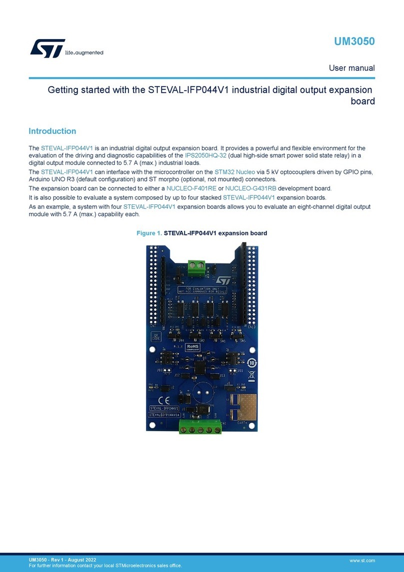
ST STEVAL-IFP044V1 User manual

ST
ST TDA911 Series Installation and operating instructions

ST
ST STM32F107Series User manual

ST
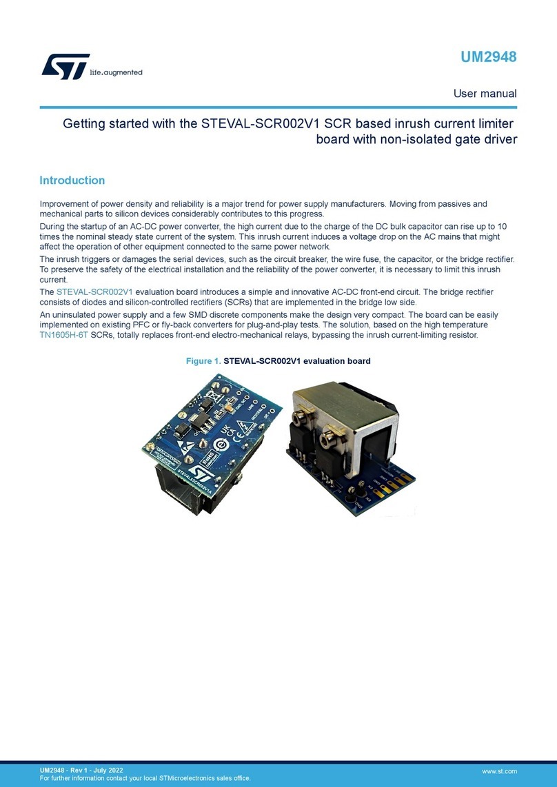
ST STEVAL-SCR002V1 User manual

ST
ST X-NUCLEO-OUT08A1 User manual

ST
ST STEVAL-IFP046V1 User manual

ST
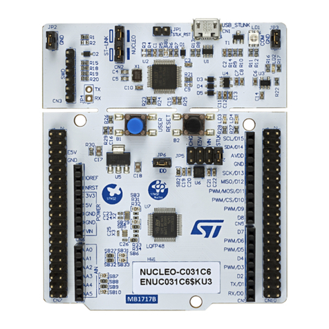
ST STM32 Nucleo User manual

ST
ST X-NUCLEO-OUT10A1 User manual
Popular Computer Hardware manuals by other brands

Simonds
Simonds CLP-274 Owners & safety manual

Seagate
Seagate Nytro 5350S NVMe SSD product manual

Avalue Technology
Avalue Technology ECM-TGUC user manual

PS Audio
PS Audio MultiWave II Installation and operation instructions

ekwb
ekwb EK-Quantum Vector FE RTX 3070 user guide

Cypress
Cypress CY62167DV18 Specification sheet