Ametek ORTEC 428 Service manual
Other Ametek Measuring Instrument manuals
Ametek
Ametek 5100P User manual

Ametek
Ametek DM330 Series User manual

Ametek
Ametek 5910 User manual
Ametek
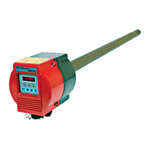
Ametek LAND Genesis WDG-1200 User manual

Ametek
Ametek 5100P User manual
Ametek
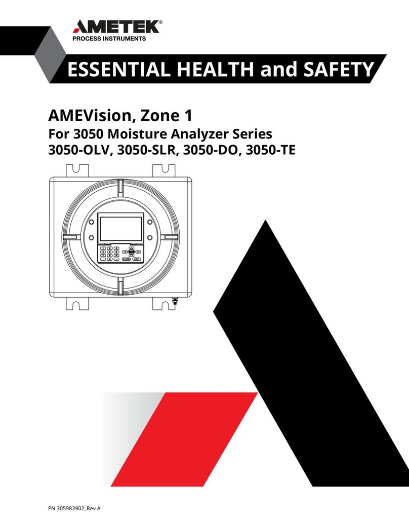
Ametek AMEVision 3050 Series User manual

Ametek
Ametek VersaSTAT LC Series User manual
Ametek
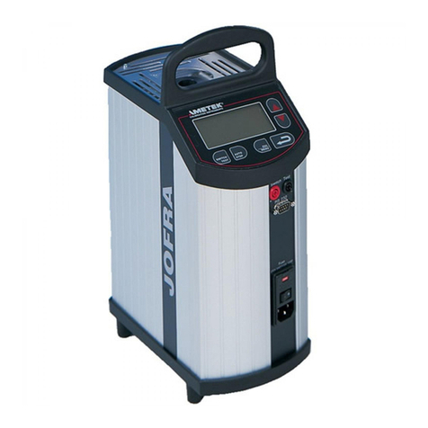
Ametek JOFRA ITC-155 A User manual
Ametek
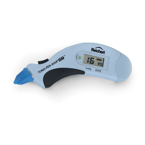
Ametek Reichert Tono-Pen AVIA Vet User manual
Ametek
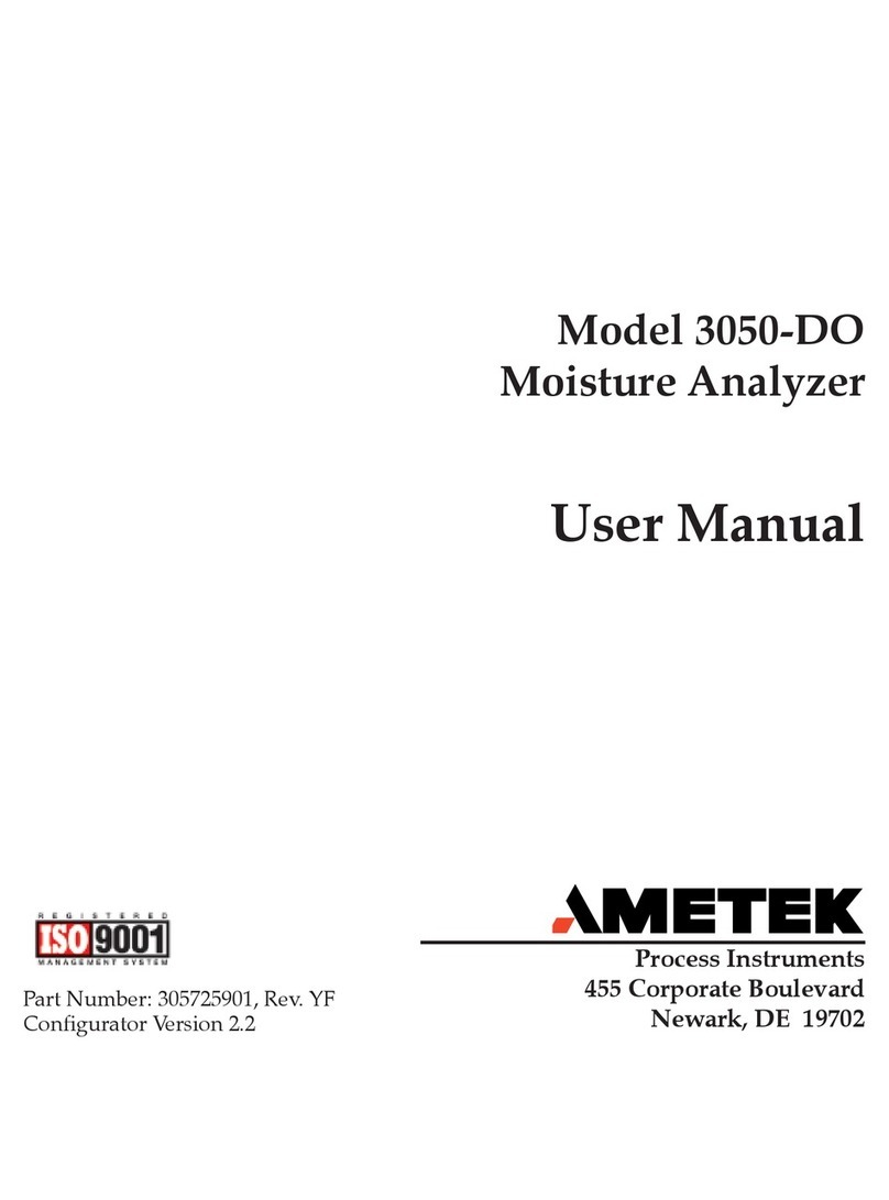
Ametek 3050-DO User manual
Ametek
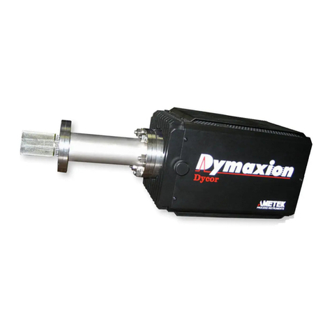
Ametek Dycor DM100 User manual
Ametek
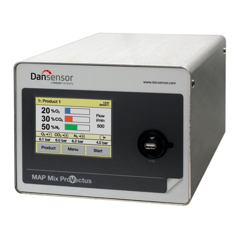
Ametek mocon Dansensor MAP Mix ProVectus User manual
Ametek
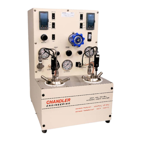
Ametek CHANDLER ENGINEERING Twin UCA 4262 User manual
Ametek
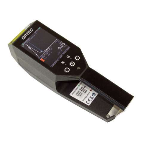
Ametek ORTEC radEAGLET User manual
Ametek
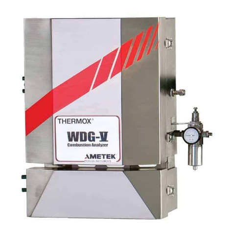
Ametek Thermox WDG-V User manual
Ametek
Ametek MFC 1000.1 User manual

Ametek
Ametek Reichert Tono-Vera User manual

Ametek
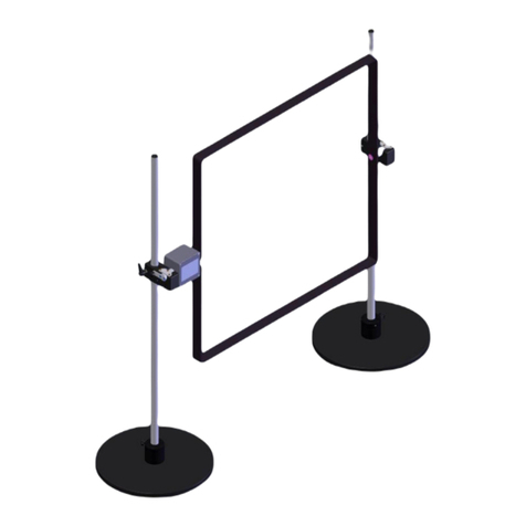
Ametek mAcal User manual
Ametek
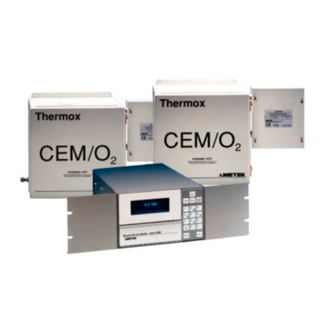
Ametek CEM/Humox User manual
Ametek
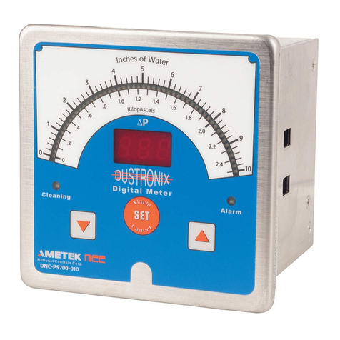
Ametek DNC-PS700-A10 Specification sheet
Popular Measuring Instrument manuals by other brands

Powerfix Profi
Powerfix Profi 278296 Operation and safety notes

Test Equipment Depot
Test Equipment Depot GVT-427B user manual

Fieldpiece
Fieldpiece ACH Operator's manual

FLYSURFER
FLYSURFER VIRON3 user manual

GMW
GMW TG uni 1 operating manual

Downeaster
Downeaster Wind & Weather Medallion Series instruction manual

Hanna Instruments
Hanna Instruments HI96725C instruction manual

Nokeval
Nokeval KMR260 quick guide

HOKUYO AUTOMATIC
HOKUYO AUTOMATIC UBG-05LN instruction manual

Fluke
Fluke 96000 Series Operator's manual

Test Products International
Test Products International SP565 user manual

General Sleep
General Sleep Zmachine Insight+ DT-200 Service manual
