MeiTrack T633L User manual

MEITRACK T633L User Guide
MEITRACK T633L User Guide

MEITRACK T633L User Guide
Copyright © 2021 Meitrack Group All rights reserved. - 2 -
Change History
File Name
MEITRACK T633L User Guide
Project
T633L
Creation Date
Update Date
2019-04-11
2021-04-02
Subproject
User Guide
Total Pages
16
Version
V1.3
Confidential
External Documentation

MEITRACK T633L User Guide
Copyright © 2021 Meitrack Group All rights reserved. - 3 -
Contents
1 Copyright and Disclaimer........................................................................................................................................... - 4 -
2 Product Introduction ................................................................................................................................................. - 4 -
2.1 Product Overview ......................................................................................................................................... - 4 -
2.2 Product Functions......................................................................................................................................... - 4 -
2.2.1 Position Tracking.................................................................................................................................. - 4 -
2.2.2 Anti-Theft............................................................................................................................................. - 4 -
2.2.3 Monitoring........................................................................................................................................... - 5 -
2.2.4 Other Functions ................................................................................................................................... - 5 -
2.2.5 Functions of Optional Accessories....................................................................................................... - 5 -
2.3 Product Features........................................................................................................................................... - 5 -
2.3.1 Analysis of driver driving behavior....................................................................................................... - 5 -
2.3.2 Emergency Alarm Detection ................................................................................................................ - 6 -
2.3.3 Maximize I/O flexibility ........................................................................................................................ - 6 -
2.3.4 Maximize Peripheral Interface............................................................................................................. - 6 -
2.3.5 CAN Interface....................................................................................................................................... - 7 -
2.4 Specifications................................................................................................................................................ - 8 -
2.5 T633L and Accessories.................................................................................................................................. - 9 -
2.6 About the T633L ........................................................................................................................................... - 9 -
2.6.1 Appearance.......................................................................................................................................... - 9 -
2.6.2 LED Indicator...................................................................................................................................... - 10 -
2.6.3 I/O Cable............................................................................................................................................ - 10 -
3 First Use................................................................................................................................................................... - 12 -
3.1 Installing the SIM Card................................................................................................................................ - 12 -
3.2 Configuring Device Parameters by Meitrack Manager ............................................................................... - 12 -
3.3 Installing GPS and GSM Antennas............................................................................................................... - 12 -
3.4 Device Connection Diagram........................................................................................................................ - 13 -
3.5 Tracking by Mobile Phone........................................................................................................................... - 14 -
4 MS03 Tracking System ............................................................................................................................................. - 16 -

MEITRACK T633L User Guide
Copyright © 2021 Meitrack Group All rights reserved. - 4 -
1Copyright and Disclaimer
Copyright © 2021 MEITRACK. All rights reserved.
and are trademarks that belong to Meitrack Group.
The user manual may be changed without notice.
Without prior written consent of Meitrack Group, this user manual, or any part thereof, may not be reproduced for
any purpose whatsoever, or transmitted in any form, either electronically or mechanically, including photocopying and
recording.
Meitrack Group shall not be liable for direct, indirect, special, incidental, or consequential damages (including but not
limited to economic losses, personal injuries, and loss of assets and property) caused by the use, inability, or illegality
to use the product or documentation.
2Product Introduction
2.1 Product Overview
The T633L is a brand new 4G vehicle tracker with multiple RS232 and RS485 interfaces. This unit can connect to
multiple accessories: RFID card reader, camera and LED Nixie Tube Display. At the same time, the T633L has a CAN
interface, which support to monitor the CANBUS data of the vehicle. In addition, it supports driving behavior analysis,
fuel level monitoring and temperature monitoring and its performance has been significantly improved.
2.2 Product Functions
2.2.1 Position Tracking
⚫GPS + LBS positioning
⚫Real-time location query
⚫Track by time interval
⚫Track by distance
⚫Cornering report
⚫Track by mobile phone
2.2.2 Anti-Theft
⚫SOS alert
⚫GPS antenna cut-off alert
⚫External power supply cut-off alert
⚫GPS blind spot alert
⚫Remote vehicle fuel/power cut-off
⚫Engine or vehicle door status alert
⚫Towing alert
⚫Geo-fence alert

MEITRACK T633L User Guide
Copyright © 2021 Meitrack Group All rights reserved. - 5 -
2.2.3 Monitoring
⚫Harsh acceleration and braking detection
⚫Idling detection
⚫Fatigue driving reminder and monitoring
⚫Speeding reminder and monitoring
⚫Driver authorization detection
⚫Fuel level monitoring
⚫Temperature monitoring
⚫Vehicle CANBUS data monitoring
⚫Harsh cornering detection
⚫Impact detection
⚫Rollover detection
2.2.4 Other Functions
⚫SMS/GPRS (TCP/UDP) communication (Meitrack protocol)
⚫Built-in 8 MB buffer for recording driving routes (Store 4,096 GPRS cache records, 64 SMS cache records, and
65,536 GPS logs)
⚫Mileage report
⚫Low power alert for internal battery
⚫Build-in 3-axis accelerometer
⚫Over-the-Air (OTA) update
2.2.5 Functions of Optional Accessories
Optional Accessory
Function
Microphone & Speaker
Two-way calling OR monitoring
iButton
Identify the driver ID and grant permission to start the vehicle.
A53 resistive fuel level sensor
Detect the fuel level.
A52 digital temperature sensor + A61 sensor
box
Detect temperature.
2 RS232 ports
RFID reader
Identify the driver ID and grant permission to start the vehicle.
Monitor driver attendance by RFID report.
Ultrasonic fuel level sensor
Detect the fuel level.
4 RS485 ports
2 camera ports
Photographing and monitoring
2 A81 LED Nixie Tube Display
ports
Display driving speed in real time and temperature.
2.3 Product Features
2.3.1 Analysis of driver driving behavior
The analysis of driving behavior includes Idle Overtime detection, Fatigue Driving detection, Overspeed detection,
Harsh Braking detection, Harsh Acceleration detection and Harsh Cornering detection, etc

MEITRACK T633L User Guide
Copyright © 2021 Meitrack Group All rights reserved. - 6 -
Idle Overtime detection: If the speed is less than 5km/h for 180 seconds, the alarm will be activated, parameters can
be modified by the B14 command or Meitrack Manager.
Fatigue Driving detection: If the vehicle has been driving for 240 minutes, the fatigue driving alarm will be activated,
parameters can be modified by the B15 command or Meitrack Manager.
Overspeed detection: Disabled by default, parameters can be modified by the B07 command or Meitrack Manager.
Harsh Braking, Harsh Acceleration and Harsh Cornering detection: the alert results vary according to the device
installation, vehicle model, vehicle weight, and driving behaviors. After the device has been installed properly, you
can use the BBD command,BC6 command and Meitrack Manager software to adjust the harsh acceleration and
braking alert values.
2.3.2 Emergency Alarm Detection
SOS Emergency Alarm: After the SOS button is pressed, the SOS alarm alarm will be triggered
Vehicle Impact Detection Emergency Alarm: The alert results vary according to the device installation, vehicle model
and vehicle weigh. After the device has been installed properly, you can use the CB4 command and Meitrack Manager
software to adjust the Impact Detection alert values.
Vehicle Rollover Detection Emergency Alarm: When the rollover Angle is greater than 45°and lasts for 10 seconds,
there will be a Rollover Alarm. The CC7 command can be used to calibrate the horizontal plane of the vehicle
2.3.3 Maximize I/O flexibility
T633L Offer outstanding configuration flexibility to cater to a wide variety of requirements and support at most 9
digital inputs, 8 outputs, 4 AD ports:.
Set to DIN high level trigger
Set to DIN low level trigger
Set to AD
Set to output
Pin 3(white)
√(IN1)
Pin 5(White&Brown)
√(IN2)
√(IN2)
√(AD3)
√(OUT5)
Pin 6(Yellow&Red)
√(IN6)
√(IN6)
√(OUT3)
Pin 7(White&Red)
√(IN3)
√(IN3)
√(AD6)
√(OUT6)
Pin 8(Blue)
√(IN4)
√(IN4)
√(AD1)
√(OUT7)
Pin 9(Blue&Brown)
√(IN5)
√(IN5)
√(AD2)
√(OUT8)
Pin 10(Yellow)
√(IN7)
√(IN7)
√(OUT1)
Pin 11(Yellow&Brown)
√(IN8)
√(IN8)
√(OUT2)
Pin 12(Green)
√(IN9)
√(OUT4)
2.3.4 Maximize Peripheral Interface
T633L supports 2 RS232 peripheral extension interfaces and 4 RS485 peripheral extension interfaces
RFID Reader
Ultrasonic Fuel Sensor
Camera
A82 LED Nixie Tube Display

MEITRACK T633L User Guide
Copyright © 2021 Meitrack Group All rights reserved. - 7 -
RS232-1
√
√(Default)
RS232-2
√(Default)
√
RS485-1
√
RS485-2
√
LED1_RS485
√
LED2_RS485
√
All above are the peripheral that T633L already supported. If necessary, Meitrack is capable of customizing any
peripherals like cameras, ultrasonic fuel sensor, LED display connected to T633L as long as they support RS232/RS485.
2.3.5 CAN Interface
The device can read CAN bus data of a vehicle that supports the FMS protocol.
The following data can be read: vehicle speed, vehicle control status, accelerator pedal position (%), total fuel
consumption, engine rotational speed, total engine run time, total mileage, engine coolant temperature, fuel level,
engine torque, ambient temperature, torque at current speed, fuel consumption rate, axle weight, service distance,
and instantaneous fuel consumption.
Note:
1. To obtain the preceding data, the vehicle must support the FMS protocol.
2. Install the device based on vehicle types. Connect vehicle's CANH and CANL wires to tracker's CANH and CANL
connectors respectively.
The CAN cable is a 4-pin cable, including: 5V power cable, ground cable, CANH and CANL.
1
5V(+)
3
CANH
2
GND(-)
4
CANL
Pin Number
Color
Description
1(5V Power +)
Red
Power output
Output voltage: 5 V
2(GND)
Black
Ground wire
3(CANH)
Brown
Used to connect a CAN bus peripheral.
4(CANL)
Orange
Used to connect a CAN bus peripheral.
MEITRACK T633L User Guide
Copyright © 2021 Meitrack Group All rights reserved. - 8 -
2.4 Specifications
Item
Specifications
Dimension
106 mm x 24.5 mm x 70 mm
Weight
190g
Power supply
DC 11.4–36 V/1.5 A
Backup battery
400 mAh/3.7 V
Power consumption
Current in sleep mode: 11 mA
Operating temperature
-20°C to 55°C(normal-temperature battery)
-5°C to 75°C(high-temperature battery)
Operating humidity
5% to 95%
Working hour
45 hours in power-saving mode
4 hours in normal mode
LED indicator
Green indicator showing the GSM signal
Blue indicator showing the GPS signal
Button/Switch
1 SOS button (for sending SMSs or dialing)
1 power button
Memory
8 MB byte
Sensor
3-axis accelerometer (used to wake the device up by vibration and detect towing alerts)
Frequency band
T633L-E:
2G GSM:B3(1800)/B8(900)
3G WCDMA:B1(2100)/B8(900)
4G FDD:B1(2100)/B3(1800)/B7(2600)/B8(900)/B20(800)/B28A(700)
T633L-A:
3G WCDMA:B2(1900)/B4(1700/2100)/B5(850)
4G FDD: B2(1900)/B4(2300)/B12(700)
T633L-AU:
2G GSM:B2(1900)/B3(1800)/B5(850)/B8(900)
3G WCDMA:B1(2100)/B2(1900)/B5(850)/B8(900)
4G FDD:B1(2100)/B2(1900)/B3(1800)/B4(2300)/B5(850)/B7(2600)/B8(900)/B28(700)
LTE TDD:B40
GPS sensitivity
-163 dB
Positioning accuracy
2.5m
GNSS
GPS/GLONASS/BEIDOU/GALILEO
I/O port
The device supports 3 digital input ports, 3 output ports, 2 AD input ports, and 1 1-Wire
digital temperature sensor (iButton) interface by default. At most 9 negative input OR
7 positive ports, 8 output ports, or 4 AD input ports can be configured. For details, see
the section 2.6.3 "I/O Cable."
2 RS485 ports (4 pins) for connecting to the LED Nixie Tube Display
2 RS485 ports (4 pins) for connecting to the camera
1 CAN bus interface (FMS protocol)
1 RS232 port (8 pins) for connecting to the RFID card reader or ultrasonic fuel sensor
1 extended RS232 port (4 pins) for connecting to the RFID reader or ultrasonic fuel

MEITRACK T633L User Guide
Copyright © 2021 Meitrack Group All rights reserved. - 9 -
sensor
1 audio port (3.5 mm)
1 Micro USB port
2.5 T633L and Accessories
T633L and standard accessories:
⚫T633L tracker
⚫External 4G antenna
⚫External GPS antenna
⚫I/O cable with an SOS button (2 meters)
⚫CD download card
⚫USB cable
⚫CANBUS convertor cable
Optional accessories:
⚫iButton
⚫Relay (12 V/24 V)
⚫A53 fuel level sensor (voltage sensor)
⚫A52 digital temperature sensor
⚫RFID reader
⚫Buzzer
⚫Camera
⚫A81 LED Nixie Tube Display
⚫Speaker and microphone
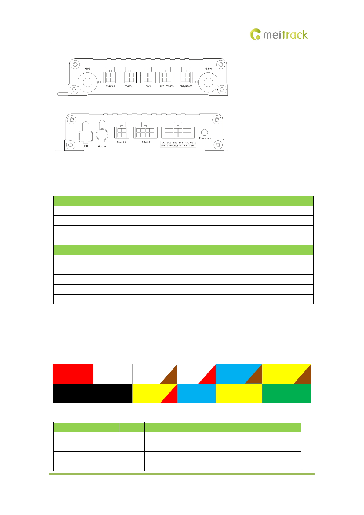
2.6 About the T633L
2.6.1 Appearance
MEITRACK T633L User Guide
Copyright © 2021 Meitrack Group All rights reserved. - 10 -
2.6.2 LED Indicator
Press and hold down the power button for 3–5 seconds to start the device.
GPS Indicator (Blue)
Steady on
A button or an input is triggered.
Blink (every 0.1 seconds)
The device is being initialized or the battery power is low.
Blink (0.1 seconds on and 2.9 seconds off)
A GPS signal is received.
Blink (1 second on and 2 seconds off)
No GPS signal is received.
GSM Indicator (Green)
Steady on
A call is coming in.
Blink (every 0.1 seconds)
The device is being initialized.
Blink (0.1 seconds on and 2.9 seconds off)
A base station signal is received.
Blink (1 second on and 2 seconds off)
No base station signal is received.
Blink (3 second on and 1 seconds off for 90 seconds )
CAN data retrieved successfully
2.6.3 I/O Cable
The I/O cable is a 12-pin cable, including the power, analog input, digital temperature sensor input, and
negative/positive input and output interfaces.
1
Power(+)
3
Input1
5
Input2
7
Input3
9
Fuel sensor
11
Output 2
2
GND(-)
4
GND(-)
6
Output3
8
AD input 1
10
Output 1
12
1-wire
Pin Number
Color
Description
1 (Power +)
Red
Positive charge of the power input, connected to the positive charge
of the vehicle battery. Input voltage: 11.4–36 V.
2 (GND)
Black
Ground wire, connected to the negative charge of the vehicle
battery or to the negative terminal.

MEITRACK T633L User Guide
Copyright © 2021 Meitrack Group All rights reserved. - 11 -
3 (Input 1)
White
Digital input 1, negative trigger (SOS button by default)
4 (GND)
Black
Ground wire, connected to input 1 (SOS button)
5 (Input 2)
White &
brown
Digital input 2 (negative trigger)
Connect to a door trigger signal cable to detect vehicle door status.
(Most Chinese, Korean, and Japanese cars are negative edge-
triggered.)
The port can be set to positive trigger, AD input 3 (0–30 V), or output
5.
6 (Output 3)
Yellow
& red
Output 3
Valid: low level (0 V)
Invalid: open collector
Maximum voltage for output open collector (invalid): 40 V
Maximum current for output low voltage (valid): 500 mA
Connect to an external relay to remotely cut off the vehicle fuel
cable or engine power supply.
The port can be set to positive or negative input 6.
7 (Input 3)
White &
red
Digital input 3 (positive trigger)
Connect to the vehicle ACC cable by default to detect the vehicle
ACC status.
The port can be set to negative trigger, AD input 6 (0–30 V), output
6.
8 (AD Input 1)
Blue
Analog input 1 with 12-bit resolution and valid voltage 0–30 V
Connect to an external sensor, such as the fuel level sensor.
The port can be set to positive or negative input 4 or output 7.
9 (Fuel level sensor input)
Blue &
brown
Analog input 2 with 12-bit resolution and valid voltage 0–30 V
There is a white plug on the AD cable, and the cable is connected to
the A53 fuel level sensor by default.
The port can be set to positive or negative input 5 or output 8.
10 (Output 1)
Yellow
Output 1
Valid: low level (0 V)
Invalid: open collector
Maximum voltage for output open collector (invalid): 40 V
Maximum current for output low voltage (valid): 400 mA
Connect to an external relay to remotely cut off the vehicle fuel
cable or engine power supply.
The port can be set to positive or negative input 7.
11 (Output 2)
Yellow
&
brown
Output 2
Valid: low level (0 V)
Invalid: open collector
Maximum voltage for output open collector (invalid): 40 V
Maximum current for output low voltage (valid): 400 mA
Connect to a buzzer.
The port can be set to positive or negative input 8.

MEITRACK T633L User Guide
Copyright © 2021 Meitrack Group All rights reserved. - 12 -
12 (1-wire, Digital
temperature sensor or
iButton input port)
Green
TTL3.3V level
Connect to the A52 digital temperature sensor or iButton by default
by using the A61 sensor box.
The port can be set to negative input 9 or output 4.
Note: The DC or AC voltage that is greater than 3.3 V is not allowed.
Otherwise, the device may be damaged.
3First Use
3.1 Installing the SIM Card
1. Loosen the screws, and remove the front cover of the device.
2. Insert the SIM card into the card slot with its gold-plated contacts facing towards the Printed Circuit Board
(PCB).
3. Close the cover, and tighten the screws.
Note:
⚫Power off the device before installing the SIM card.
⚫Ensure that the SIM card has sufficient balance.
⚫Ensure that the phone card PIN lock has been closed properly.
⚫Ensure that the SIM card in the device has subscribed the caller ID service if you want to use your authorized
phone number to call the device.
3.2 Configuring Device Parameters by Meitrack Manager
This section describes how to use Meitrack Manager (version 6.0.2.4 or later) to configure the device on a computer.
Procedure:
1. Install the USB driver and Meitrack Manager.
2. Connect the device to a computer by using the USB cable.
3. Run Meitrack Manager, then the following dialog box will appear:
Turn on the device, then Meitrack Manager will detect the device model automatically and the parameter page will
appear accordingly.
For details about Meitrack Manager, see the MEITRACK Manager User Guide.
3.3 Installing GPS and GSM Antennas
Connect the GSM antenna to the connector which is labeled "GSM". The GSM antenna is non-directional, so you can
hide it in any place of a vehicle.
Connect the GPS antenna to the connector which is labeled "GPS". It is recommended that the antenna is facing up
MEITRACK T633L User Guide
Copyright © 2021 Meitrack Group All rights reserved. - 13 -
to the sky and the antenna side with words is downwards. Secure the antenna by using double sided tapes.
Note: Do not install the GPS antenna at a metal covered place.
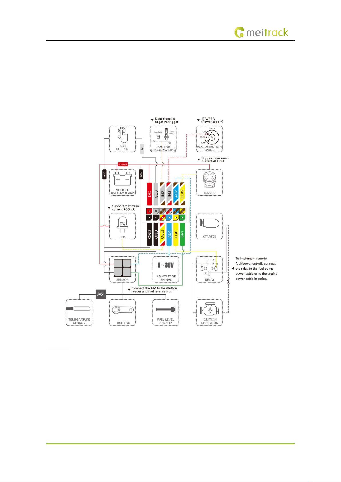
3.4 Device Connection Diagram

MEITRACK T633L User Guide
Copyright © 2021 Meitrack Group All rights reserved. - 14 -
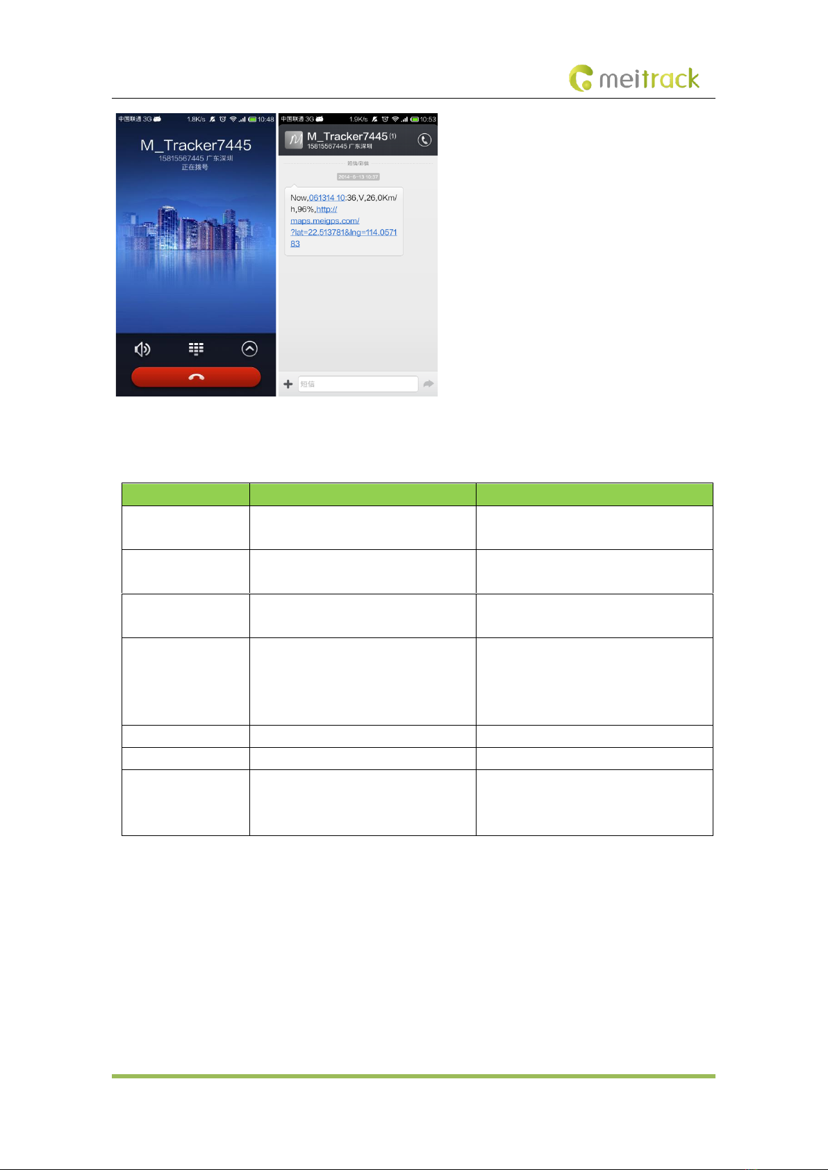
3.5 Tracking by Mobile Phone
Call or send the 0000,A00 command by SMS to the device's SIM card number. The device will reply to an SMS with a
map link.
Click the SMS link. The device's location will be displayed on Google Maps on your mobile phone.
Note: Ensure that the device's SIM card number has subscribed the caller ID service. Otherwise, the tracking function
by mobile phone will be unavailable.
MEITRACK T633L User Guide
Copyright © 2021 Meitrack Group All rights reserved. - 15 -
SMS example:
Now,061314 10:36,V,26,0Km/h,96%,http://maps.meigps.com/?lat=22.513781&lng=114.057183
The following table describes the SMS format:
Parameter
Description
Remarks
Now
Indicates the current location.
SMS header: indicates the current location
or the alert type.
061314 10:36
Indicates the date and time in MMDDYY
hh:mm format.
None
V
The GPS is invalid.
A = Valid
V = Invalid
26
Indicates the GSM signal strength.
Value: 1–32
The larger the value is, the stronger the
signal is. If the value is greater than 12, GPRS
reaches the normal level.
0Km/h
Indicates the speed.
Unit: km/h
96%
Indicates the remaining battery power.
None
http://maps.meigps.c
om/?lat=22.513781&l
ng=114.057183
Indicates the map link.
Latitude: 22.513781
Longitude: 114.057183
None

MEITRACK T633L User Guide
Copyright © 2021 Meitrack Group All rights reserved. - 16 -
4MS03 Tracking System
Visit http://ms03.trackingmate.com, enter the user name and password, and log in to the MS03. (Purchase the login
account from your provider.)
For more information about how to add a tracker, see the MEITRACK GPS Tracking System MS03 User Guide (chapter
4 "Getting Started").
The MS03 supports the following functions:
⚫Track by time interval or distance.
⚫Query historical trips.
⚫Set polygonal geo-fences.
⚫Bind driver and vehicle information.
⚫View various reports.
⚫Send commands in batches.
⚫Support OTA updates.
For details, see the MEITRACK GPS Tracking System MS03 User Guide.
Other manuals for T633L
2
Table of contents
Other MeiTrack Automobile Accessories manuals


 User instructions")