MEL Systems Tele4 User manual

Connecting Sensorsto
the Internet ofThings
T
emperature
Level
Pressure
Flow
Vibration
Flow
Wind speed
Wind direction
Humidity
CO
Distance
Hours run
Fault
Intruder
Collision
State
Weight
pH
Conductivity
Salinity
T
OC
KNOWLEDGE
User Interfaces
Platform
Communications
Gateways
SENSORS

Getting to Know…
The Tele4 makes remote monitoring
simple and affordable, interfacing with
sensors, taking periodic readings and
transmitting them over the mobile
phone networks.
• Compatible with 1000s of sensors
• Remotely programmable
• Self-contained, weatherproof
• Proven and reliable
Technical Specifications
Parameter Details
Inputs
4 (4 – 20 mA, 0 – 10 V DC sensors or volt free contacts).
Expansion cards: 5 channel pulse (volt free, 10 Hz max.) & RS232 / R S485
(contact Mel-Systems regarding protocols).
Outputs Optional 2 relay outputs controlled either remotely or when threshold breached.
Communications GSM (4G (CatM1 / NB1) with 2G fallback – worldwide frequencies).
Data Logging 80 per channel, (first in first out).
Power Supply Battery, 6-24Vdc. solar and mains options.
Sensor Excitation Will provide power to sensors (5 V or 21.6 V, 31 mA max.) for a programmable length of time.
Environmental IP67, -20 to +65ºC.
Programming Normally remotely from Tele4view or locally via USB (Windows software free of charge from
Mel-Systems. Mini USB not provided by Mel-Systems).
Configurable Parameters System Inputs
Wake up interval (min: 1 min, max: 24 hr) Type (analogue or digital)
Transmit interval (min: 1 min, max: 24 hr) Tag name
Modem state (including idle, transmit on
power up, pollable)
Units of measure
Zero & span (scaling) and linearisation
Antenna selection (internal or external) Alarm thresholds (10 high (rising) and 10 low
(falling))
Synchronisation time Call out delay
Transmission window
Sensor excitation time and settling voltage
upon waking the device, touch left button for
immediate reading
Display
The built-in back lit 40x40mm LCD display acts as a local gauge to help test the device and
ensure it is communicating well. It is also used to check sensors and wiring. Can be used as a
local display to show measured values on wake up.
The Tele4
Battery life depends on regime. The Tele4 is designed to maximise battery life. More
frequent readings, weak signal and cold temperatures will shorten battery life. Battery
duration also dependent on the type of sensor used. Typical life is 4 years if powering a 2
wire, 4-20 mA sensor for 2 seconds and transmitting once per day. Only use Mel-Systems
approved batteries.
Intelligent solar regulator maximises battery life and solar charging potential
and includes pre charge conditioning if battery is in poor condition. There is
also temperature com pensation, meaning charge rate is adjusted according to
battery temperature, maximizing battery life.
Solar capability depends on orientation, sight of sun and location ( ie the
further from the equator the less power from the sun). In England, 10 minute
transmissions possible, in Scotland need a 2nd solar cell to achieve this.
Dimensions
185 × 337 mm base plate
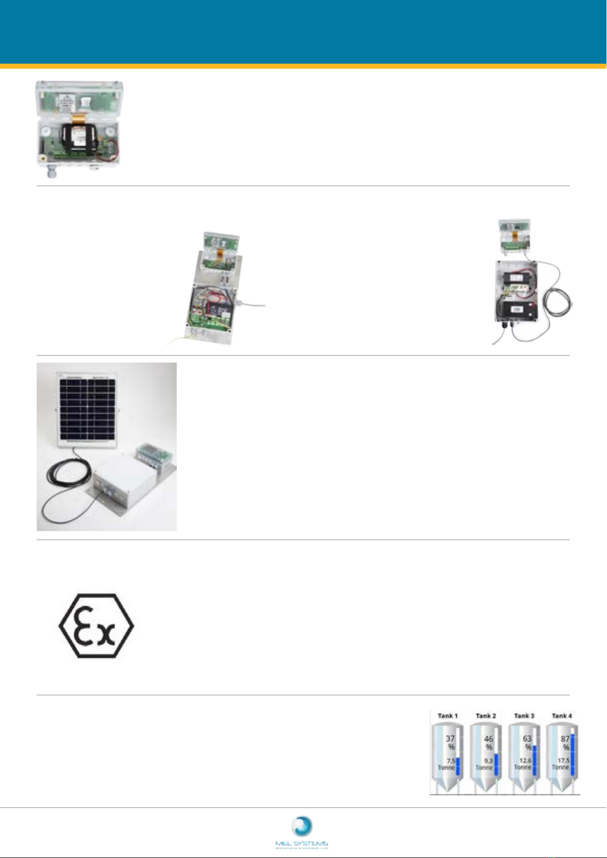
The Tele4 is housed in a panel with the barriers. This panel needs to be in the safe area
and suitable sensors fitted in the field.
This augmented solution offers a sophisticated interface on site, with high
resolution, colour display of actual process (eg tank levels & graphics). It is used
where more complex calculations and commands are needed on site. Tele4AS
offers instant response to programmable inputs/events, triggering immediate
alarms and beacons Contact Mel-Systems to discover more about Tele4AS and
bespoke, application specific solutions.
Enclosure
400 × 300 mm wall mount panel with
hinged door.
ATEX Barrier(s)
Includes up to 4 ATEX barries,
such as MTL 554
Sensor Cabling
Consider inductance and capacitance of
cable as well as characteristics of sensor.
For SPS Ex (from Mel-Systems) with
LAPP12420 cable max. = 754m.
Tele4/S runs on 6-24Vdc. Allow 0.5 A. Ensure supply is well regulated.
For mains power 110/230 Vac, options are:
Tele4/SSM runs from an internal battery.
Tele4/S/SOL SYS runs from a 10 Watt solar power and lead acid
battery via an intelligent charge regulator.
Tele4/S/...ATEX for use in explosive atmospheres. For 110/230 Vac power supply.
Tele4AS (Augmented Solution)
/MPSU Mains (110 / 230 Vac)
power supply with backup
battery and regulator, housed
in a weatherproof enclosure
and a Tele4 fixed on base
plate (185 x 371 mm).
Provides 6 Vdc to Tele4
UPS 12 V Uninterruptable
power supply is a separate box
(262 × 188 mm). Mains 110 /
230 Vac in 12 Vdc maintained
output via battery backup.
Battery can typically support
50 transmissions. IP54
protection rating. Run cable
from UPS 12 V to Tele4.

Tele4 Optional Additions
EXPANSION CARDS
EXTERNAL ANTENNA
The Tele4 can have expansion cards fitted such as a 5 channel pulse counting card, providing
a system that has 4 analogue inputs and 5 pulse inputs in total. Pulse inputs can be used for a
variety of applications, including flow and electricity meter reading.
The expansion cards fit neatly inside the Tele4 and present the terminals for easy connection of
the pulse signals. The pulses need to be slower than 10 Hz (10 pulses per second) and must be
volt free contacts.
The count can be configured to either reset when successfully transmitted to the server, or
rollover (can count to 4,294,967,295).
Insert card into Ex socket.
You will see the corresponding LED quickly flash when a pulse is seen, if fitted correctly.
Also available: serial port RS232 & RS485. (Contact Mel-Systems regarding protocols)
The Tele4 has an integral antenna and has been designed
to achieve optimal signal strength to the mobile phone
networks. However, consider connecting an external antenna
too, if mounting in an area of poor signal strength improve
the signal or inside a metal enclosure.
The SMA connector present on the board usually requires a
mating connector that is too large to fit through the standard
M12 cable glands that are supplied.
A fitting kit is provided but if sourcing own antenna, an
M12 – M16 cable gland adapter will be required. Also consider
the need to bore out centre to get the connector through.
Select external antenna via menu or set in the configuration.
Wire in to green connector
plug and tighten screw.
Insert connector into plug
in terminal connector
123
• Hosted software platform
• Receives data from the Tele4
and other remote IoT devices
• Allows for viewing of data via
internet connected devices in
any browser
• Remote Tele4 configuration
• Alarms sent by email
• Pull data via API
• Safe and secure
WEB
PORTALS USER
MANAGEMENT
ANALYTICS
API’S
RULES &
ALARMS DEVICE
MANAGEMENT
DATABASE
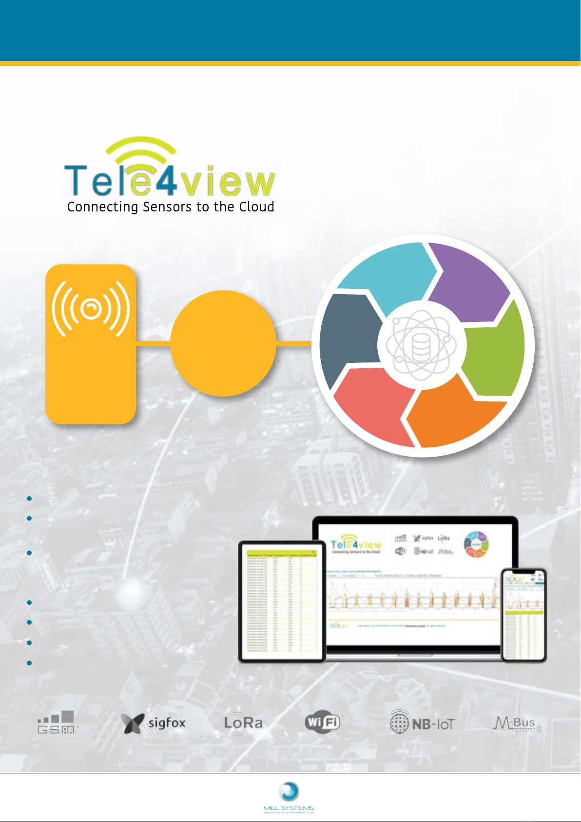
Any
sensor
Anywhere
Tele4
Devices that
send the readings
from the remote
locations
Tele4view
Tele4 Quick Start Guide
HOW TELE WORKS
TELE QUICK INSTALL GUIDE
Unit asleep; screen
and GSM off
Wake up interval – powers the
sensors and takes readings
Transmit interval (or upon
alarm) it powers up the GSM
engine
Readings & alarms are
sent via GSM
The system is usually set up so unit
powers down between readings.
The real time clock counts time and
wakes the device up depending on how
it is programmed.
10 high and 10 low alarm thresholds
for each of the 4 channels – if threshold
is breached then Tele4 transmits
immediately. The unit can log 80
readings per channel.
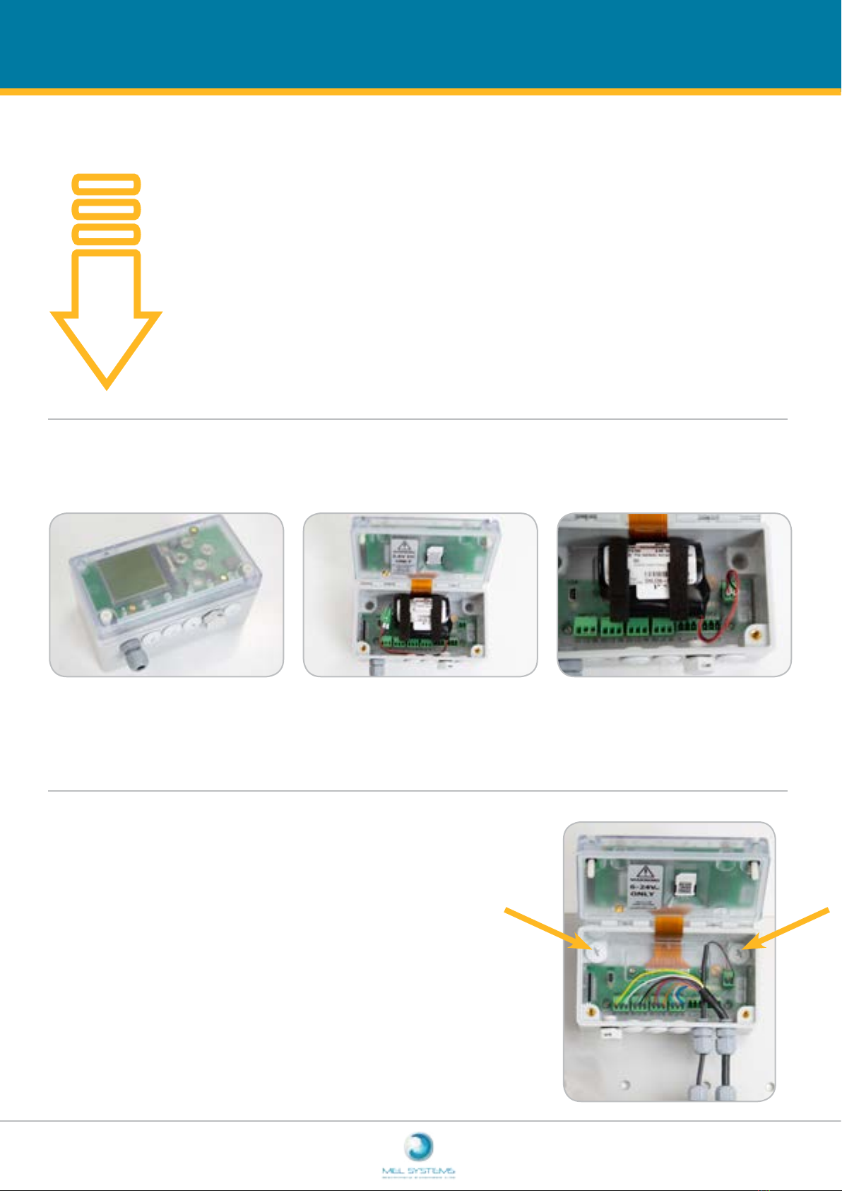
1. Unpack & Open Up the Tele4
2. Mount the Tele4
Place the unit on a flat surface
and loosen the 2 nylon screws
in the bottom corners to open.
Allen key required.
Use the 2 mounting holes used to fasten the Tele4 down to a
baseplate, wall or other surface.
The unit needs a mobile phone signal to operate, so try to avoid
mounting inside metal cabinets or underground. The unit is
weatherproof, but ensure:
• All cable glands and breather glands on the unit have an ‘O’
ring fitted and are suciently tightened.
• If no cable is going through the gland, that blanking plugs
are fitted. Blanking plugs also need fitting over the fixings
inside the device.
• Both screws on the top are tightened, but not over tightened.
• The seal around the lid is correctly in place.
Open the Tele4. The interior will
vary depending on unit. The
image shows the /SSM model
with a battery.
Ensure the SIM card is installed.
Plug in the power source.
Tele4 Quick Start Guide
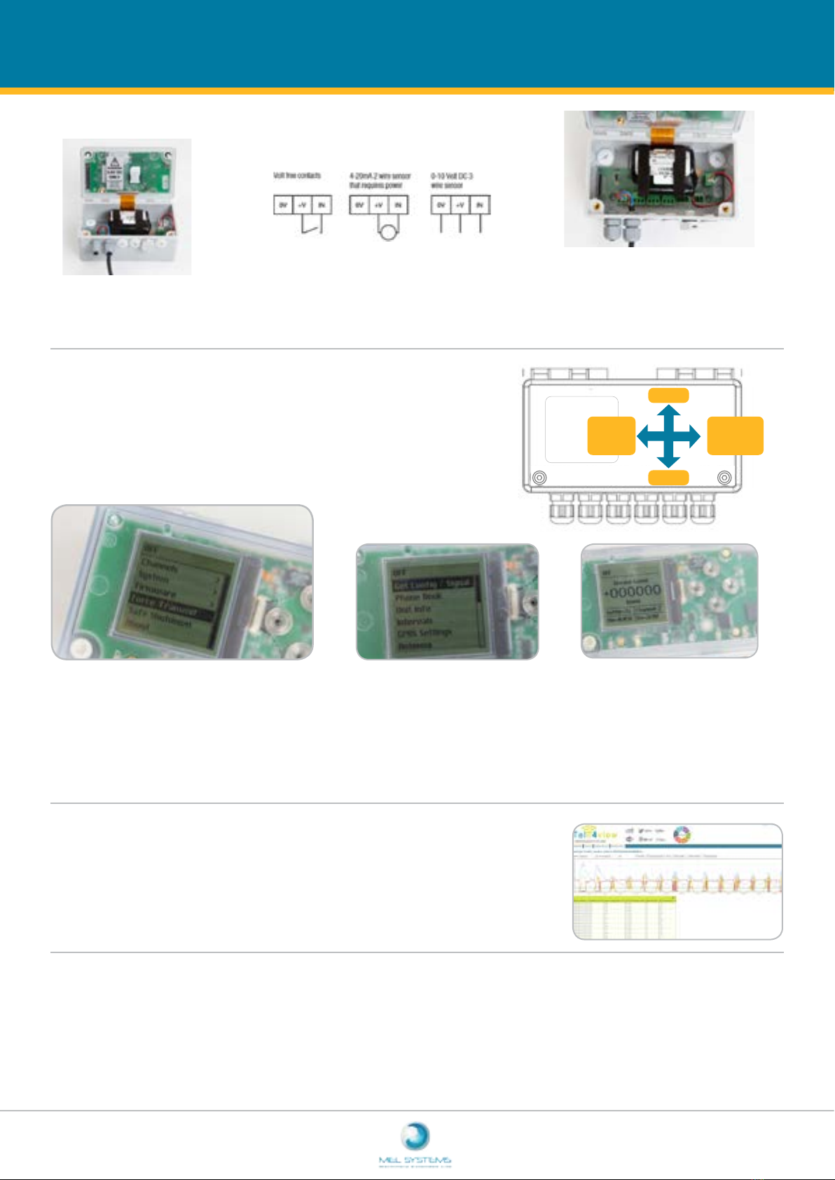
3. Connect the Sensors
4. Navigate the Tele4
5. View Data
6. Programming
Run the sensor’s cable
through the gland.
Unplug the green
connector and wire in as
Plug the connector into the
correct input channel and
tighten the gland. Ensure
cable is through the gland.
Press any button to wake up the Tele4 and enter
PIN (default = 1234). Press right after 4th digit to enter.
Force transmit. Move down to Force
Transmit, and right to select. Watch the
progress bar and wait for the unit to
transmit. Once complete, the data will be
available for viewing on Tele4view. The unit
will countdown for 40 seconds then enter
Run Mode. The screen will turn off
Login details will normally be sent by email. If not, contact Mel-
Systems support. Once logged in, a summary of your units will
be visible. Click on view to the left of the device’s name to see
the historical data. Mel-Systems support can change the name of
units and inputs if required.
Units can be remotely programmed from Tele4view. It is possible to change how often readings
are taken & sent, alter scaling and alarm thresholds for each of the input channels and much more
(see Configurable Parameters earlier). To make changes please contact Mel-Systems support. The
configuration will be held on the server and be downloaded to the device when it next communicates,
and then use the new settings in the future. Select ‘Force transmit’ rather than waiting for the next time
the device transmits in order to reconfigure sooner.
Check signal. Enter PIN,
select System, select Get
Config / Signal. Signal is
scaled between 0 -31 (31
= best) and at least 10
recommended for GSM
connection.
Immediate reading. Touch
device to wake and left for
live reading. Keep pressing
left to swap between
channels and read different
sensors.
1 2 1 23 4
Go back
a level of
the menu
Select the
highlighted
option
Up
Down
Mel Systems s.r.l. - Head Oce: Via Enrico Toti, 29 - 20900 Monza (MB) Italy
Operations: Piazza Giulio Prinetti 27/b - 23807 Merate (LC) Italy
Remote Condition
Monitoring
Lower Operational &
Maintenance Costs
Extend Asset Life
Improve Safety
Enhance Sales
Propositions
Introduce New
Revenue Streams
Improve Service
Levels
Connecting assets to the cloud is now
essential for businesses to remain
competitive.
Mel-Systems’ innovative Tele4 IoT telemetry
device (or sensor gateway) makes remote
monitoring simple.
Tele4 gets sensor data reliably and
affordably into the cloud via 4G (2G backup).
• 4 analogue inputs,
• Expansion cards for pulse counting,
options for RS232, RS485 and CANBUS
• Compact IP67 enclosure
• Solar, battery and external power options
• Operational temperatures -25 to +65°C
Compatible with thousands of sensors,
Tele4 is ideal in a vast range of global
environments and applications.
In conjunction with our Tele4view cloud,
Tele4 helps customers improve margin,
achieve competitive advantage and develop
new revenue streams.
Monitor. Control. Maintain. Alert.
Table of contents


