SUTO S452 Manual

English
Instruction and operation manual
S452
Thermal mass flow sensor
for heavy duty industries

Dear Customer,
Thank you for choosing our product.
Please read the operating instructions in full and carefully observe them
before starting up the device. The manufacturer cannot be held liable
for any damage which occurs as a result of non-observance or non-
compliance with this manual.
Should the device be tampered with in any manner other than a
procedure which is described and specified in the manual, the warranty
is void and the manufacturer is e empt from liability.
The device is designed e clusively for the described application.
SUTO offers no guarantee for the suitability for any other purpose.
SUTO is also not liable for consequential damage resulting from the
delivery, capability or use of this device.
2 S452

1 Safety instructions
Table of Contents
1 Safety instructions......................................................................4
2 Registered trademarks.................................................................6
3 Application.................................................................................7
4 Features....................................................................................7
5 Technical data.............................................................................8
5.1 General data.........................................................................8
5.2 Electrical data.......................................................................9
5.3 Output signals......................................................................9
5.4 Accuracy .............................................................................9
5.5 Flow ranges..........................................................................9
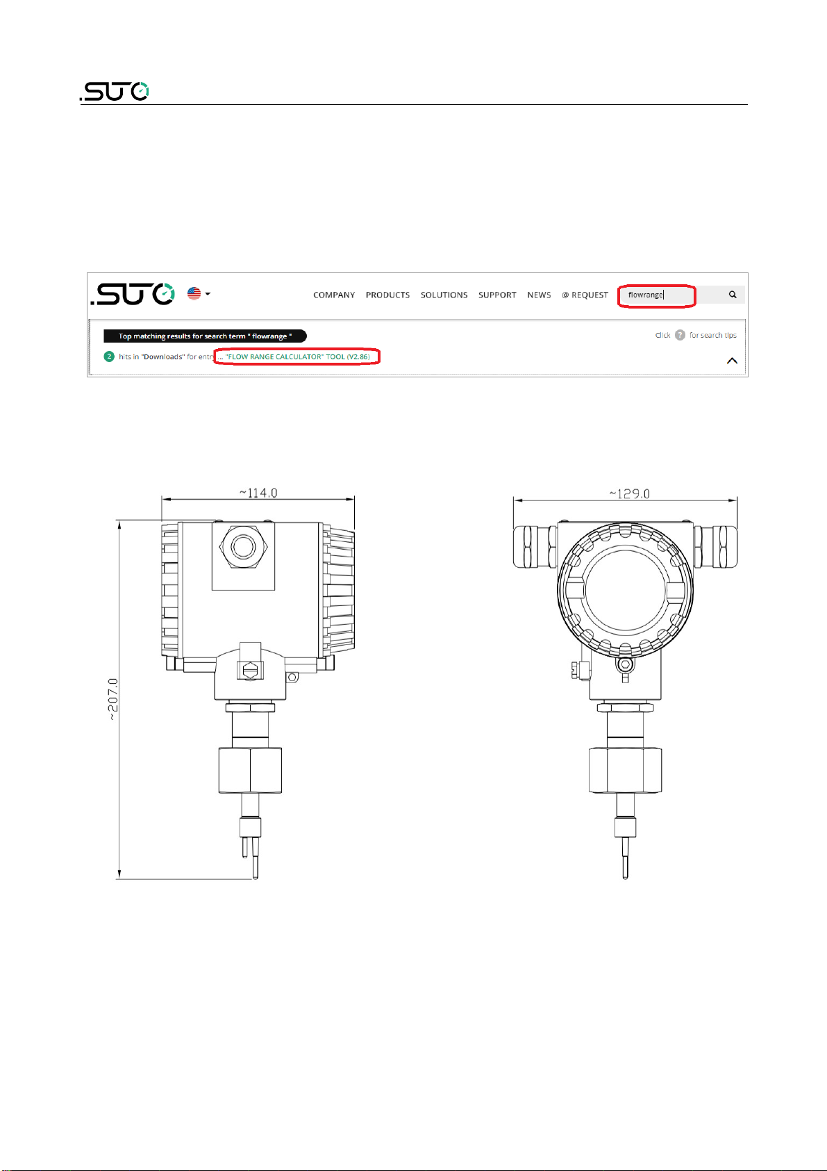
6 Dimensional drawing..................................................................10
8 Determining the installation point................................................11
8.1 Additional inlet and outlet sections.........................................12
9 Sensor installation ....................................................................13
9.1 Installing the flow sensor......................................................13
9.2 Removing the flow sensor ....................................................14
9.3 Re-installation after maintenance..........................................15
9.4 Electrical connection ..........................................................15
9.4.1 Connection diagram..............................................................15
9.4.2 Pin assignment.....................................................................16
10 Signal outputs.........................................................................18
10.1 Analog and pulse outputs ...................................................18
10.1.1 Analog output.....................................................................18
10.1.2 Pulse output.......................................................................18
10.2 HART output ....................................................................20
10.3 Modbus output .................................................................20
10.4 M-Bus output ...................................................................22
11 Configuration..........................................................................22
12 Optional accessories................................................................24
12.1 Sensor display...................................................................24
12.2 Service kit........................................................................24
13 Calibration..............................................................................25
14 Maintenance...........................................................................25
15 Disposal or waste....................................................................25
16 Appendi A - Modbus communication e ample............................26
S452 3

1 Safety instructions
Please check if this instruction manual matches the
product type
Please observe all notes and instructions indicated in this
manual. It contains essential information which must be
observed before and during installation, operation and
maintenance. Therefore this instruction manual must be read carefully
by the technician as well as by the responsible user or qualified
personnel.
This instruction manual must be available at the operation site of the
flow sensor at any time. In case of any obscurities or questions,
regarding this manual or the product, please contact the manufacturer.
WARNING!
Compressed air!
Any contact with quickly escaping air or bursting
parts of the compressed air system can lead to
serious injuries or even death!
•Do not e ceed the ma imum permitted pressure range (see
sensors label).
•Only use pressure tight installation material.
•Avoid that persons get hit by escaping air or bursting parts of the
instrument.
•The system must be pressureless during maintenance work.
WARNING!
Voltage used for supply!
Any contact with energized parts of the product, may
lead to a electrical shock which can lead to serious
injuries or even death!
•Consider all regulations for electrical installations.
•The system must be disconnected from any power supply during
maintenance work.
•Any electrical work on the system is only allowed by authorized
qualified personal.
4 S452

1 Safety instructions
ATTENTION!
Permitted operating parameters!
Observe the permitted operating parameters, any
operation exceeding this parameters can lead to
malfunctions and may lead to damage on the
instrument or the system
•Do not e ceed the permitted operating parameters.
•Make sure the product is operated in its permitted limitations.
•Do not e ceed or undercut the permitted storage and operation
temperature and pressure.
•The product should be maintained and calibrated frequently, at
least annually.
General safety instructions
•It is allowed to use the product in e plosive areas. Please contact
the manufacturer.
•Please observe the national regulations before/during installation
and operation.
Remarks
•It is not allowed to disassemble the product.
•Always use spanner to mount the product properly.
ATTENTION!
Measurement values can be affected by malfunction!
The product must be installed properly and
frequently maintained, otherwise it may lead to
wrong measurement values, which can lead to
wrong results
•Always observe the direction of the flow when installing the
sensor. The direction is indicated on the housing.
•Do not e ceed the ma imum operation temperature at the sensors
tip.
•Avoid condensation on the sensor element as this will affect the
accuracy enormously.
S452 5

1 Safety instructions
Storage and transportation
•Make sure that the transportation temperature of the sensor
without display is between -30 ... +70°C and with display between
-10 ... +60°C.
•For transportation it is recommended to use the packaging which
comes with the sensor.
•Please make sure that the storage temperature of the sensor is
between -10 ... +50°C.
•Avoid direct UV and solar radiation during storage.
•For the storage the humidity must be <90% with no condensation.
2 Registered trademarks
SUTO®Registered trademark of SUTO iTEC
MODBUS®Registered trademark of the Modbus Organization,
Hopkinton, USA
HART®Registered trademark of the HART Communication
Foundation, Austin, USA
PROFIBUS® Registered trademark of the PROFIBUS User
Organization, Karlsruhe, Germany
Android™,
Google Play
Trademarks of Google LLC
6 S452

3 Application
3 Application
The S452 flow sensor is designed for the e plosive areas and is mainly
used to measure compressed air and process gases in industrial
environments.
The S452 can measure the following parameters for the compressed air
or gases:
•Velocity
•Volume flow
•Total consumption
The default factory settings are: Velocity in m/s, Volume flow in m3/h
and Total Consumption in m3. Other units can be programmed by the
optional display or the service kit.
4 Features
•Direct measurement of mass flow and standard flow without the
need of pressure and temperature compensation.
•In-line types for smaller pipes.
•No moving parts, no clogging.
•All sensor parts which come into contact with the measurement
medium are made of stainless steel 316L.
•Robust metal enclosure suitable for outdoor applications in harsh
environments.
•Wireless Bluetooth interface for sensor settings onsite
•Optional display on the sensor, showing flow rate, consumption,
medium temperature and diagnostic result.
S452 7

5 Technical data
5 Technical data
5 1 General data
Measuring range 0.4 ... 92.7 sm/s (standard range calibration)
0.8 ... 185 sm/s (ma range calibration)
1.0 … 224 sm/s (high speed calibration)
(See section 4.5 for flow measurement ranges
in different tube diameters)
* sm/s: standard meter per second
Parameters Standard unit flow: m3/h
Available units: m3/min, l/min, l/s, cfm, kg/h,
kg/min, kg/s
Standard velocity unit: m/s
Reference conditions ISO1217, 20°C, 1000 mbar (Standard-Unit)
DIN1343, 0°C, 1013.25 mbar (Norm-Unit)
Principle of
measurement
Thermal mass flow
Sensor Resistive sensor
Measured medium Air, gas (non corrosive gas)
Operating temperature -40 ... +100°C (medium temperature)
-40 ... +65°C (ambient temperature)
Humidity of the
measured medium
< 90%, no condensation
Operating pressure 0 ... 4.0 MPa
Housing material Al alloy
Material of the probe
tube, sensor head and
the screwing
Stainless steel 1.4404 (SUS 316L)
Protection class IP67
Dimensions See Chapter Dimensional drawing.
Display (optional) Graphic display, 128 64
Tube diameter DN15 … DN80
Screwing thread M32 1.5
8 S452

5 Technical data
Weight 1.25 kg (instrument only, and the measuring
section is not included)
5 2 Electrical data
Power supply 16 ... 30 VDC, 5 W
5 3 Output signals
Analog output See section 10.1.1
Pulse output See section 10.1.2
HART output See section 10.2
Modbus output See section 10.3
M-Bus output See section 10.4
5 4 Accuracy
Accuracy* ±(1.5% of reading + 0.3% full scale)
Stated accuracy at: Ambient/process temperature +23°C ±3°C
Ambient/process humidity <90%, no
condensation
Process pressure at 0.6 MPa
Repeatability 0.25% of reading
* The specified accuracy is valid only within the minimum and ma imum
flow rates that are stated in Section 5.5.
5 5 Flow ranges
The stated flow ranges are valid under the following conditions:
Standard flow in air; Reference pressure: 1000 hPa; Reference
Temperature: +20°C
S452 9
Inch DN
1/2” DN15 0.2 ... 45.6 0.4 ... 91.0 0.48 ... 110.16
3/4” DN20 0.4 ... 89.1 0.9 ... 177.8 1.09 ... 215.3
1” DN25 0.6 ... 147.7 1.2 ... 294.7 1.82 ... 356.85
1 1/2” DN40 1.5 ... 366.7 2.9 ... 731.9 4.36 ... 886.18
2” DN50 2.4 ... 600 4.8 ... 1198 7.26 ... 1450.04
2 1/2” DN65 4.1 ... 1027 8.2 ... 2049 12.1 ... 2480.44
3” DN80 5.7 ... 1424 11.4 ... 2841 16.94 ... 3441.91
S-Range (m3/h) M-Range (m3/h) HS-Range (m3/h)

5 Technical data
Remarks:
To calculate flow ranges based on pipe and reference conditions in your
site, download and install the "Flow range calculator" tool for free from
http://www.suto-itec.com.
To fast access the tool download page, enter "flowrange" (without
spaces) in the search field and click the search result.
6 Dimensional drawing
Unit: mm
7
10 S452

8 Determining the installation point
To maintain the accuracy stated in the technical data, the sensor must
be inserted in the centre of a straight pipe section with unhindered flow
characteristics.
Unhindered flow characteristics are achieved if the section in front of the
sensor (inlet) and behind the sensor (outlet) are sufficiently long,
absolutely straight and free of obstructions such as edges, seams,
curves and so on.
Please consider that enough space e ists at your site for a adequate
installation as described in this manual.
ATTENTION!
Wrong measurement is possible if the sensor is not
installed correctly
•Pay attention to the design of the inlet and outlet section.
Obstructions can cause counter-flow turbulence as well as
turbulence in the direction of the flow.
•It is strongly recommended not to install S452 permanently in wet
environment which e ists usually right after a compressor outlet.
S452 11

8 Determining the installation point
8 1 Additional inlet and outlet sections
The S452 with tube diameters from DN15 to DN25 already has the
required inlet and outlet sections. No additional straight sections are
needed.
For the S452 with diameters from DN32 to DN80, the S452 has a
shortened inlet section and requires additional straight sections at the
inlet and outlet. The additional length for the particular diameters are
listed in the table below.
Flow obstructions
before the
measurement
section
Additional
length for
DN32
[mm]
Additional
length for
DN40
[mm]
Additional
length for
DN50
[mm]
Additional
length for
DN65
[mm]
Additional
length for
DN80
[mm]
inlet outlet inlet outlet inlet outlet inlet outlet inlet outlet
Slight curve
(bend <90°C)
175 - 227.8 9.5 362.2 65.5 551.8 144.5 760.8 204.5
Reduction (Tube
narrows towards
measurement
section)
265 - 353.5 9.5 521,5 65.5 758.5 144.5 938.5 204.5
E pansion (Tube
e pands towards
measurement
section)
265 - 353.5 9.5 521.5 65.5 758.5 144.5 938.5 204.5
90°C bend or T
piece
265 - 353.5 9.5 521.5 65.5 758.5 144.5 938.5 204.5
2 90°C bends on
one level
445 - 563 9.5 787 65.5 1103 144.5 1343 204.5
2 90°C bends 3
dimensional change
of direction
985 - 1191.5 9.5 1583.5 65.5 2136.5 144.5 2556.5 204.5
Shut-off valve 1345 - 1610.5 9.5 2114.5 65.5 2825.5 144.5 3365.5 204,5
12 S452

9 Sensor installation
Before installing the sensor, please make sure that all components listed
below are included in your package.
Qty Description Part no.
1 Sensor S695 0452
1 Sealing ring No P/N
1 Measuring section A1301 ... A1306 (R thread)
A1321 … A1328 (Flange, EN-1092-1)
A1341 … A1348 (Flange, ANSI 16.5)
1 Bluetooth dongle No P/N
1 USB disk (with the
service Software stored)
No P/N
1 Instruction manual No P/N
1 Calibration certificate No P/N
9 1 Installing the flow sensor
The S452 is shipped with the mounted measurement section. When
installing the device, please make sure the following:
•The flow direction indicated on the S452 housing is consistent with
the flow direction of the compressed air or gas.
•The gas flows from the inlet (long pipe section) to the outlet (short
pipe section) as illustrated in the picture below.
S452 13

9 Sensor installation
9 2 Removing the flow sensor
The following steps e plain the procedure of an appropriate removal of
the sensor.
ATTENTION!
Only remove the sensor if the system is in a
pressure-less condition
1. Hold the sensor.
2. Release the terminal nut at the
connection thread.
3. Pull out the shaft slowly.
4. The measuring section can be closed
with the optional closing cap so the
system can work normally during
maintenance.
14 S452

9 Sensor installation
9 3 Re-installation after maintenance
•The re-installation of the measurement device is simple because
the sensor unit fits into the pipe section only in one position.
•Please make sure that the O-shaped sealing ring is installed.
•Tighten the terminal nut to secure the sensor.
9 4 Electrical connection
When installing the cables please consider following points:
•Keep the stripped and twisted length of cable shield as short as
possible.
•Screen and ground the signal lines.
•Unused cable entries must be closed with closers.
•Cable outer diameter should be between 6 and 8 mm.
•Single wire cross section area should be between 0.25 ... 0.75
mm2.
•The thread size for the cable glands is M20 / 1.5.
9 4 1 Connection diagram
Remove the back cover from the S452, and the pin layout is shown
below.
S452 15

9 Sensor installation
9 4 2 Pin assignment
S452 provides four output options. The pin assignment of these options
are given in the following table.
Pin Output options
Pulse and analog Modbus M-Bus HART
1 GNDSDI GNDSDI GNDSDI GNDSDI
2 +VB+VB+VB+VB
3 -VB-VB-VB-VB
4 SDI SDI SDI SDI
5 DIR DIR DIR DIR
6 DIR DIR DIR DIR
7 SW SW SW NA
8 SW SW SW NA
9 -I1-I1-I1-I1 / -HART
10 +I1+I1+I1+I1 / +HART
11 -I2+D M1 NA
12 +I2-D M2 NA
13 NA GNDMNA NA
14 Earth Earth Earth Earth
15 Earth Earth Earth Earth
16 Earth Earth Earth Earth
16 S452

9 Sensor installation
Legend to pin assignment
SDI = Digital signal (internal use) SW = Isolated pulse output
GNDSDI = Ground for SDI DIR = Flow direction input
+VB= Positive supply voltage +D = Modbus data+
-VB= Negative supply voltage -D = Modbus data -
+l1= Positive signal output
(analog 1)
M = M-Bus data
-I1= Negative signal output
(analog 1)
NA = Not applicable
+l2= Positive signal output
(analog 2)
-I2= Negative signal output
(analog 2)
S452 17

10 Signal outputs
10 Signal outputs
10 1 Analog and pulse outputs
If the S452 is purchased with the output option of analog and pulse
signals, it provides 2 analog outputs and 1 pulse output. All signals are
electrically isolated.
10 1 1 Analog output
The analog output can be used as an active output (current is sourced
through the positive connection pin) or passive output. In the passive
configuration a current signal is modulated into the e ternal signal
voltage.
Active : 4 to 20mA, RL < 400 Ω
Passive : 4 to 20mA, supply voltage 18... 30 VDC, RL < 500 Ω
For HART : RL ≥ 250 Ω
Uncertainty : < 0.3 % of reading
Resolution : 0.005 mA
10 1 2 Pulse output
No switch, no polarity required, galv. Isolate
Ma . rating : 30 VDC, 200 mA
Pulse width : 10 ... 100 msec (depending on flow rate)
The ma imum number of pulse per second is limited to 45 pulse per
second. As a result depending on the flow rate and the selected
consumption unit the ma imum flow rate is limited to the values in the
table below.
18 S452

10 Signal outputs
Pulse /
consumption unit
Max flow
1/1 1/10 1/100
m3/h 162,000 1,620,000 16,200,000
m3/min 2,700 27,000 270,000
l/min 2,700 27,000 270,000
cfm 2,700 27,000 270,000
Kg/h 162,000 1,620,000 16,200,000
Kg/min 2,700 27,000 270,000
Kg/s 45 450 4,500
Default Configurable by service software
Pulse connection diagram
Variant 1:
Variant 2:
S452 19

10 Signal outputs
10 2 HART output
If the S452 is purchased with the output option of HART, the HART
signal is modulated on analog output 1. In case S452 is used in a multi-
drop configuration (more than 1 slave on the 4-20 mA line) the analog
output cannot be used.
Device type :Slave
Polling address :1 to 15
Bus address can be set through software
Physical interface :BELL 202
Protocol version :V 5.2
Tag :S452
Tag description :Flow meter
Frame/parity/Stop :8, 0, 1
10 3 Modbus output
If the S452 is purchased with the output option of Modbus, it provides
one analog output and one pulse output.
The Modbus communication requires to activate terminal resistors at the
last device on the bus system. If the S452 is the last device on the bus
system, the DIP switches on the connector board should be set to “ON”
position.
Termination resistor
network switch
Device type : Slave
Address rage : 1 to 251
Bus address can be set through software
Physical
interface
: RS485 in accordance with EIA/TIA-485 standard
Baud rates : 1200, 2400, 4800, 9600, 19200, 38400, 57600,
115200
Transm. mode : ASCll, RTU
Response time : Direct data access = 0 to 255 ms (can be configured)
20 S452
Other manuals for S452
2
Table of contents
Other SUTO Accessories manuals
Popular Accessories manuals by other brands

Ziton
Ziton ZX832-3 Series Installation sheet

FAAST
FAAST 8251BPI nstallation and Maintenance Instructions

KROHNE
KROHNE OPTISENS TSS 2000 Handbook

Eaton
Eaton WSPS 05 instruction manual

Franklin Electric
Franklin Electric SubDrive Duplex Alternator installation manual

NEW BRUNSWICK SCIENTIFIC
NEW BRUNSWICK SCIENTIFIC Innova CO-170 Guide to operations