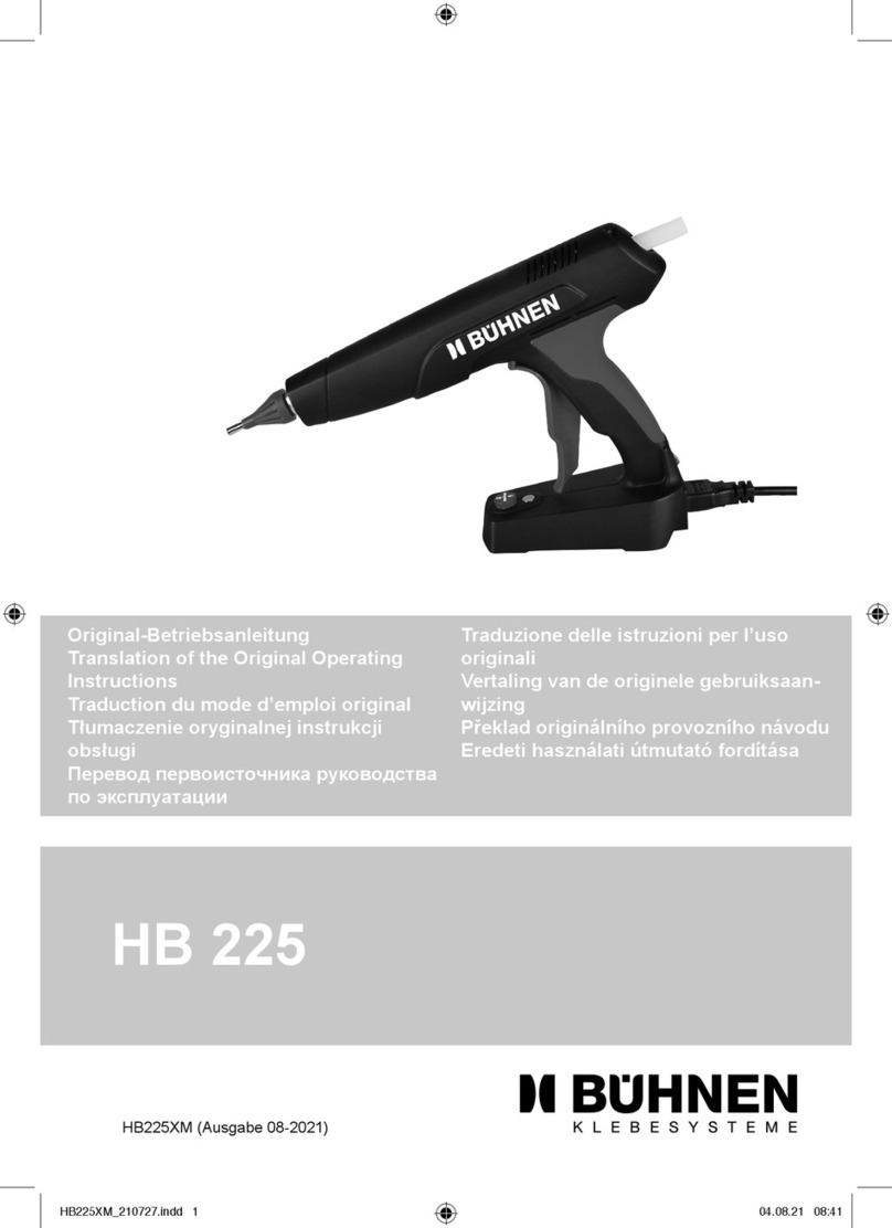
Meler MV User manual

MV
APPLICATOR
INSTRUCCIONS
MANUAL
MA-5096-E 020915
GLUING SOLUTIONS

Published by:
Meler Gluing Solutions, S.A
P.I. Los Agustinos, calle G, nave D-43
E - 31160 ORCOYEN Navarra (España)
Tel.: + 34 948 351 110
Fax: + 34 948 351 130
e-mail: info@meler.eu
www.meler.eu
Edition September 2015
© Copyright by Meler
All rights reserved. Its reproduction, diffusion or use by electronic or other
means of all or any part of this document without the express authorization of
its owner is strictly prohibited.
The specifications and information contained in this manual may be modified
without prior notice.

TABLE OF CONTENTS MA-5096-E MV APPLICATOR MANUAL
INDICE
1. SAFETY GUIDELINES 1-1
General 1-1
Symbols 1-1
Mechanical components 1-2
Electrical components 1-2
Hydraulic components 1-2
Thermal components 1-2
Noise 1-2
Materials 1-3
2. INTRODUCTION 2-1
Description 2-1
Intended use 2-2
Applicator identification 2-2
Main components 2-3
3. INSTALLATION 3-1
Unpacking 3-1
Introduction 3-1
Installation of the applicator 3-1
Hose diameter 8 mm 3-1
Hose diameter 13 mm 3-3
Double motor and air flow activation system 3-3
4. USE 4-1
Starting up the applicator 4-1
Pneumatic trigger 4-1
Electric trigger 4-2

MELER GLUING SOLUTIONS TABLE OF CONTENTS
Application adjustments 4-3
Adjusting the flow of adhesive 4-3
Adjusting the air flow (applicator for swirling) 4-4
5. TECHNICAL FEATURES 5-1
Models 5-1
Electrical connections 5-2
Maximum dimensions (swirl model) 5-2
6. MAINTENANCE 6-1
Access to the interior of the applicator 6-1
Replacing the body union fitting (pneumatic trigger) 6-2
Replacing the pneumatic trigger of the applicator 6-2
Replacing the module 6-4
Replacing the sensor and heating resistance 6-4
7. SPARE PARTS LIST 7-1
A. MANUAL APPLICATOR ASSEMBLY 7-2
B. DOUBLE MOTOR AND AIR FLOW ACTIVATION SYSTEM 7-3
C. HOSE SUPPORT (OPTIONAL) 7-3

SAFETY GUIDELINES
1-1
MA-5096-E MV APPLICATOR MANUAL
1. SAFETY GUIDELINES
General
The information contained in this section applies not only to everyday machine
operation, but also to any procedure carried out on it, whether for preventive
maintenance or in the case of repairs and the replacement of worn out parts.
It is very important to observe the safety warnings in this manual at all times.
Failure to do so may result in personal injury and/or damage to the machine
or the rest of the installation.
Before beginning work on the product, read this manual carefully, and in case
of any doubt, contact our Technical Service Center. We are available for any
clarification that you might need.
Keep manuals in perfect condition and within reach of personnel that use the
machine and perform maintenance on it.
Also provide necessary safety material: appropriate clothing, footwear, gloves
and safety glasses.
In all cases, observe local regulations regarding risk prevention and safety.
Symbols
The symbols used on both the applicator and in this manual always represent
the type of risk we are exposed to. Failure to abide by a warning signal may
result in personal injury and/or damage to the machine or the rest of the
installation.
Warning: Risk of electrical shock. Carelessness may produce injury or death.
Warning: Hot zone with high temperatures. Risk of burns. Use thermal
protective equipment.
Warning: System under pressure. Risk of burns or particle projection. Use
thermal protective equipment and goggles.
Warning: Important information for the correct use of the system. May include
one or several of the previous hazards, and therefore must be kept in mind to
avoid damage and injury.

MELER GLUING SOLUTIONS
1-2
SAFETY GUIDELINES
Mechanical components
The applicator equipment installation where the applicator is placed, uses
moveable parts that may cause damage or injury. Use the equipment correctly,
and do not remove the safety guards while the equipment is in operation;
prevent the risk of possible entrapment due to moving mechanical parts.
Do not use the product if the safety devices are not in place or appear to be
inadequately installed.
The manual applicator does not presents any risks in terms of mechanical
movements.
Electrical components
The MV applicator operates with a one-phase current LN ~ 230V 50Hz + PE at
a certain rated power. Be sure the the applicator connector is placed correctly
on the hose electrical connector.
Once the applicator is connected to the hose, it will be correctly grounded as
well.
Hydraulic components
As this is a pressurized system, precautions related to this type of equipment
must be observed.
Before each operation, always make sure that the adhesive circuit is
completely free of pressure. There is a high risk of hot particle projection,
along with the corresponding danger of burns.
Use caution with the residual pressure that may remain in the hoses when the
adhesive cools. When reheated, there is a risk of hot particle projection if the
outputs are left open.
Thermal components
The MV applicator operates with temperatures reaching up to 200 °C (392 °F).
Although the applicator has insulated covers, must be operated using
adequate protection (clothing, footwear, gloves and protective glasses) that
completely cover exposed parts of the body.
In case of burns, immediately cool the affected area with clean, cold water.
Seek medical attention as soon as possible from the company’s medical
service or the nearest hospital. Do not try to remove the adhesive material
from the skin.
Noise
The noise level of the system is well below allowable levels, and therefore
does not present a specific risk to be taken into consideration.

SAFETY GUIDELINES
1-3
MA-5096-E MV APPLICATOR MANUAL
Materials
Meler applicators for adhesives are designed for use with different hot-melt
adhesives. They should not be used with any other type of material, which may
cause personal injury or damage to internal system components.
Always use original Meler’ components and replacement parts, which
guarantee the correct system operation and service.
When using adhesive, follow the corresponding guidelines found in the
Technical and Safety Sheets provided by the manufacturer. Pay special
attention to the advised work temperatures in order to prevent adhesive
burning and degradation.
Ventilate the work area adequately in order to remove the vapors produced.
Avoid the prolonged inhalation of these vapors.

MELER GLUING SOLUTIONS
1-4
SAFETY GUIDELINES
This page is intentionally left blank.

INTRODUCTION
2-1
MA-5096-E MV APPLICATOR MANUAL
2. INTRODUCTION
Description
The Meler manual MV applicator is used to apply adhesive vertically on
horizontal surfaces, for both swirl and bead applications.
The manual applicator is held by the grip and its natural position is with the
nozzle pointing downwards, as shown in the image.
The substrate to apply remains motionless while the applicator moves in the
various directions required for application.

MELER GLUING SOLUTIONS
2-2
INTRODUCTION
Intended use
The manual MV applicator is designed for use in the following conditions:
• Applicators for melting and pumping adhesive up to a temperature of
200ºC.
• Use the applicator with Meler parts or accessories.
• Install the applicator in compliance with the current safety regulations
and the instructions in this manual (hydraulic connection, electrical
connection, pneumatic connection).
• Do not use the applicator in explosive environments.
• Use the melters in line with the safety instructions included in this
manual, as well as on the labels included on the equipment, using
adequate means of protection with each operating mode.
Applicator identification
Please indicate the reference and serial number of your manual applicator
when ordering spare parts or requesting support from our Service Centre.
This and other technical information can be found on the nameplate attached
to the applicator.

INTRODUCTION
2-3
MA-5096-E MV APPLICATOR MANUAL
Main components
1. Trigger (pneumatic or electric).
2. Grip.
3. Wire harness.
4. Hose-applicator connection coupling.
5. Electrical insulation casing.
6. Applicator module.
7. Distributor body (for air or cables).
8. Heated body.
9. Flow regulator (swirl version) .
1
2
5
6
7
8
9
4
3

MELER GLUING SOLUTIONS
2-4
INTRODUCTION
This page does not contain any text.

INSTALLATION
3-1
MA-5096-E MV APPLICATOR MANUAL
3. INSTALLATION
Warning: The manual MV applicator is installed in equipment with state-
of-the-art technologies and with certain foreseeable risks. Therefore, only
qualified personnel with sufficient training and experience should be allowed
to use, install or repair this equipment.
Unpacking
Before installing the manual applicator, it should be removed from the
packaging and inspected to detect any possible deterioration or damage.
Notify your Meler Representative or the Main Office of any defect, even to the
outer packaging.
Introduction
The manual MV applicator is supplied with the necessary elements for its
installation and use. However, some components may have to be supplied by
the user, depending on each specific installation:
• Air tube diameter 6 mm.
• Support or metal wire to keep the applicator suspended at all times.
Installation of the applicator
Hose diameter 8 mm
Before installing the MV applicator, make sure that the site intended for
installation allows obstacle-free placement, connection and use of the entire
system.
Take the following steps for proper installation of the applicator::

MELER GLUING SOLUTIONS INSTALLATION
3-2
1. Use two 19 mm wrenches to tighten the female thread of the nose to
the male thread of the applicator coupling.
2. Place the thermal protector for the hydraulic hose-applicator
connection.
3. Use a screwdriver to loosen the two screws and separate the two parts
of the protector and place it on the coupling. Finally, tighten the screws.
4. Connect the electrical connections of the applicator male connector to
the female connector of the hose.
5. Place the applicator on its support. Place the metal cable in the
housing above the applicator grip
Female thread
Male thread

INSTALLATION
3-3
MA-5096-E MV APPLICATOR MANUAL
6. Place the pneumatic tube (external diameter 6 mm) in the pneumatic
coupling (fast plug connection).
Hose diameter 13 mm
Repeat the same steps taken with the 8 mm hose but previously connect the
corresponding hose adapter to the applicator coupling.
Warning: When placing this adapter, the length of the coupling is longer than
for the 8 mm hose; therefore, the thermal protector will not cover the entire
hydraulic connection.
Double motor and air flow activation system
Applicators with an electric trigger may have the option of activating both the
motor and air flow. This can be done by installing an auxiliary control box; the
connections to both the melter and the applicator are indicated in the control
box:
Hose adapter with Ø13mm
Applicator coupling + hose adapter with
Ø13mm + hose coupling

MELER GLUING SOLUTIONS INSTALLATION
3-4
13 45672
1. ON/OFF switch
2. Air inlet to the electrovalve.
3. Silencer.
4. Air outlet from the electrovalve.
5. Electrical connection to the applicator.
6. Electrical connection to the melter.
7. Electrical connection input.

USING THE APPLICATOR
4-1
MA-5096-E MV APPLICATOR MANUAL
4. USE
This section explains how to operate the manual MV applicator. Although the
equipment is easy to operate, it should not be used by untrained personnel.
Warning: Improper use of the applicator may cause damage to the equipment
itself or the person using it.
Starting up the applicator
To use the applicator, the corresponding melter will need to have pumping
permission.
Make sure that the applicator is receiving air pressure (6 bar).
Pneumatic trigger
Press the pneumatic trigger to allow air flow and open the module on the
applicator to allow the adhesive to flow out of the nozzle. To stop applying
adhesive, release the trigger to cut off the air supply to the module and stop
the application procedure.
Pneumatic diagram (bead version):
1- Air inlet
2- Pneumatic trigger
3- Module
4- Applicator body
1
2
4
3

MELER GLUING SOLUTIONS
4-2
USING THE APPLICATOR
Pneumatic diagram (swirl version):
Electric trigger
The following processes take place when the electric trigger is pressed:
• A voltage signal is sent to the electrovalve to allow air supply to the
module and start the application procedure.
• The motor (gear type melter in automatic mode) activation contact
closes so the melter pump operates only when the trigger is pressed.
6
1
2
3
5
4
1- Air inlet
2- Pneumatic trigger
3- Mechanical choke
4- Module
5- Swirl mini-module
6- Applicator body

USING THE APPLICATOR
4-3
MA-5096-E MV APPLICATOR MANUAL
Electric and pneumatic diagrams (swirl version):
Electric and pneumatic diagrams (bead version):
Application adjustments
Adjusting the flow of adhesive
The flow of adhesive needed for application is not adjusted from the MV
applicator, but from the melter unit of the corresponding installation.
If the Meler melter is supplied with a piston pump, the flow is adjusted by the
pressure regulator on the equipment.
If the Meler melter is supplied with a gear pump, the flow can be adjusted two
ways; either by adjusting the motor revolutions (preferably) or by adjusting the
pressure using the bypass valve.
1- Air inlet
2- Electrovalve
3- Electric trigger
4- Electrical power supply
5- Mechanical choke
6- Module
7- Swirl mini-module
8- Applicator body
1- Air inlet
2- Electrovalve
3- Electric trigger
4- Electrical power supply
5- Module
6- Applicator body
4
3
5
6
2
1
4
3
6
752
1
8

MELER GLUING SOLUTIONS
4-4
USING THE APPLICATOR
Adjusting the air flow (applicator for swirling)
The air flow is adjusted from the applicator itself. Make sure that the
applicator is receiving a pressure of 6 bar.
The applicator is equipped with a mechanical air choke on the applicator body.
None of the side plates have to be removed to handle the air cut-off; all that is
needed is a 4 mm Allen wrench to rotate the choke mechanism.
Turn the screw to the left to increase air flow and to the right to reduce it.
Table of contents