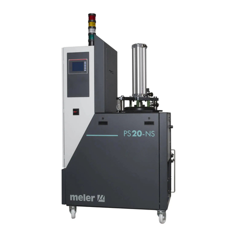
Meler PS 20 NON STOP+ User manual

GLUING SOLUTIONS
MA-5195-ENG 010620
ADHESIVE
MELTER
PS20
NON STOP +
INSTRUCTIONS
MANUAL

Published by:
Focke Meler Gluing Solutions, S.A.
Pol. Arazuri-Orkoien, c/B, nº3 A
E-31170 Arazuri - Navarra - Spain
Phone: +34 948 351 110
info@meler.eu - www.meler.eu
A Focke Group Company
Edition June 2020
© Copyright by Focke Meler
All rights reserved. Its reproduction, diffusion or use by electronic or other
means of all or any part of this document without the express authorization of
its owner is strictly prohibited.
The specifications and information contained in this manual may be modified
without prior notice.
This manual is a translation of the original that was written by Focke Meler
Gluing Solutions, S. A in spanish language. If there is any discrepancy between
the different versions of this manual, the original written in the spanish
language shall prevail. Focke Meler Gluing Solutions, S. A shall not be liable
in any way for any damages and/or losses that may be directly or indirectly
derived from discrepancies between the original version of the manual and this
translation.

TABLE OF CONTENTS MA-5195-GBR PS20 NON STOP+ DRUM UNLOADER MANUAL
INDEX
1. SAFETY GUIDELINES 1-1
General 1-1
Symbols 1-1
Mechanical components 1-2
Electrical components 1-2
Hydraulic components 1-2
Pneumatic components 1-2
Thermal components 1-3
Materials 1-3
Noise emission declaration 1-3
Intended use 1-4
Limited use 1-4
2. INTRODUCTION 2-1
Modes of operation 2-2
Identifying the melting equipment 2-2
Main components 2-3
Control panel components 2-4
PS20 NS+ range 2-5
Pneumatic by-pass valve pressure control system (VP) 2-6
3. INSTALLATION 3-1
Introduction 3-1
Installation requirements 3-1
Free space 3-1
Electrical Consumption 3-2
Compressed air 3-2
Other factors 3-3
Unpacking 3-3
Contents 3-3
Mounting the equipment 3-3
Electrical power connection 3-4

FOCKE MELER GLUING SOLUTIONS TABLE OF CONTENTS
Pneumatic connection 3-4
Hose and applicator connection 3-5
Parameter Programming 3-5
External I/O connections 3-6
Connecting external inputs and outputs 3-8
4. MELTER OPERATION 4-1
General information 4-1
Filling the tank 4-1
Melter plate cylinder movements 4-3
Configuration of pushing plate parameters 4-5
Starting up the melter equipment 4-6
Manual pumping permmision 4-7
Melter equipment display 4-8
General characteristics 4-9
Navigation icons 4-9
Save changes 4-9
Interpretación de las pantallas 4-9
Home display 4-10
General temperature status 4-10
Alarms status 4-11
Calendar status 4-11
Melter plate status 4-11
Pumping status 4-12
Temperature status 4-12
Temperature and Heating Shortcut displays 4-13
Programming of temperatures 4-14
Programming of statuses 4-14
Menú Calendars 4-14
Units and Lenguage Menu 4-15
Date and time configuration 4-15
Alarms and warnings 4-15
Pumping control menu 4-16

TABLE OF CONTENTS MA-5195-GBR PS20 NON STOP+ DRUM UNLOADER MANUAL
Modes of operation 4-17
Operating mode with internal pumping control and internal speed control 4-17
Operating mode with internal pumping control and external speed control 4-18
Operating mode with external pumping control and internal speed control 4-19
Operating mode with external pumping control and external speed control 4-20
Configuring speed ramp 4-21
Main Menu 4-21
‘1. Heating’ Menu 4-22
1.1 Heating zones 4-22
1.2 Sequential Heating 4-23
1.3 Inhibitions 4-23
1.4 Auto Standby - OFF 4-24
1.5 Extra temperature settings 4-25
‘2. General settings’ Menu 4-26
2.1 Password management 4-26
2.2 Extra settings 4-27
2.3 Configuration of input and output signals 4-28
2.4 Restore default values 4-28
‘3. Load’ Menu 4-29
Screen 1: Minimum adhesive level sensor 4-29
‘4. Statistics’ Menu 4-29
‘5. Pumping’ Menu 4-30
Automatic pumping block function 4-31
‘Automatic pumping block’ enabled 4-31
‘Automatic pumping block’ disabled 4-32
‘Turning off after resetting’ function 4-33
‘Turning off after resetting’ enabled 4-33
‘Turning off after resetting’ disabled 4-34
Configuration of turning on and activating pumping 4-34
Wireless communication (Wi-Fi) 4-36
Connection configuration 4-36
Standby function 4-37

FOCKE MELER GLUING SOLUTIONS TABLE OF CONTENTS
Bypass valve regulation 4-38
Manual valve control 4-38
Pneumatic valve control (optional) 4-38
Bypass valve pressure control (VP) 4-39
Activating and configuring the VP system 4-39
Turning off the melter equipment 4-40
Application for PC 4-41
5. MAINTENANCE 5-1
Equipment cleaning 5-1
Depressurizing the system 5-2
Cleaning the tank 5-2
Changing adhesive type 5-2
Cleaning burnt adhesive 5-3
Emptying the tank 5-3
Cleaning the bottom of tank 5-4
Cleaning the push plate 5-6
Cleaning the distributor 5-6
Cleaning the capacitive sensor 5-7
Sensitivity adjustment of the capacitive sensor 5-7
Verification of the sensor regulation 5-8
Pump maintenance 5-9
Inspecting for leaks 5-9
Motor-gear maintenance 5-9
Cleaning the motor fan 5-9
Checking the lubricant 5-9
Recommended lubricants 5-10
Thermostats maintenance 5-10

TABLE OF CONTENTS MA-5195-GBR PS20 NON STOP+ DRUM UNLOADER MANUAL
6. TECHNICAL CHARACTERISTICS 6-1
Generals 6-1
Dimensions 6-2
7. ELECTRICAL DRAWINGS 7-1
8. PNEUMATIC DRAWING 8-1
Components list 8-1
Pneumatic by-pass valve pressure control system (VP) 8-3
9. SPARE PARTS LIST 9-1
A. COVER ASSEMBLY 9-3
B. TANK GROUP 9-4
C. SIMPLE DISTRIBUTOR 9-6
D. DOUBLE DISTRIBUTOR 9-7
E. FILTER AND PRESSURE VALVE GROUP 9-8
F. MOTOR-PUMP GROUP 9-9
G. ELECTRICAL CABINET 9-10
H. PNEUMATIC GROUP 9-12
EC DECLARATION OF CONFORMITY 10-1

FOCKE MELER GLUING SOLUTIONS TABLE OF CONTENTS
This page is intentionally left blank.

SAFETY GUIDELINES
1-1
MA-5195-ENG PS20 NON STOP+ DRUM UNLOADER
1. SAFETY GUIDELINES
General
The information contained in this section applies not only to everyday
equipment operation, but also to any procedure carried out on it, whether for
preventive maintenance or in the case of repairs and the replacement of worn
out parts.
It is very important to observe the safety warnings in this manual at all times.
Failure to do so may result in personal injury and/or damage to the equipment
or the rest of the installation.
Before beginning work on the equipment, read this manual carefully, and in
case of any doubt, contact our Technical Service Center. We are available for
any clarification that you might need.
Keep manuals in perfect condition and within reach of personnel that use the
equipment and perform maintenance on it.
Also provide necessary safety material: appropriate clothing, footwear, gloves
and safety glasses.
In all cases, observe local regulations regarding risk prevention and safety.
Symbols
The symbols used on both the melter/applicator equipment and in this manual
always represent the type of risk we are exposed to. Failure to abide by a
warning signal may result in personal injury and/or damage to the equipment
or the rest of the installation.
Warning: Risk of electrical shock. Carelessness may produce injury or death.
Warning: Hot zone with high temperatures. Risk of burns. Use thermal
protective equipment.
Warning: System under pressure. Risk of burns or particle projection. Use
thermal protective equipment and glasses.
Warning: Important information for the correct use of the system. May include
one or several of the previous hazards, and therefore must be kept in mind to
avoid damage and injury.
Warning: Dangerous area. Risk of entrapment. Carelessness may produce
injury or death.

FOCKE MELER GLUING SOLUTIONS
1-2
SAFETY GUIDELINES
Mechanical components
The hot-melt installation, which is installed to this device, requires moving
parts that can cause damage. Use the equipment correctly, and do not remove
the safety guards while the equipment is in operation; prevent the risk of
possible entrapment due to moving mechanical parts.
Do not use the equipment if the safety devices are not in place or appear to be
inadequately installed.
For maintenance or repair operations, stop the movement of moveable parts
by turning off the main switch.
The device has no moving mechanical parts, so it does not pose risks to
consider in this section.
Electrical components
The system works with single-phase or three-phase current of a certain
power. Never handle the equipment with the power connected, as this may
result in powerful electrical shocks.
The installation must be correctly grounded.
The installation’s power cable conductors must match the required electric
current and voltage.
Periodically inspect the cables to check for crushing, wear and tear, as well as
to prevent tripping and falls as a result of their placement.
Although the system meets EMC requirements, it is inadvisable to use
devices that transmit high levels of radiation, i.e., mobile phones or soldering
equipment in their vecinity.
Hydraulic components
As this is a pressurized system, precautions related to this type of equipment
must be observed.
Before each operation, always make sure that the adhesive circuit is
completely free of pressure. There is a high risk of hot particle projection,
along with the corresponding danger of burns.
Use caution with the residual pressure that may remain in the hoses when the
adhesive cools. When reheated, there is a risk of hot particle projection if the
outputs are left open.
Pneumatic components
Some equipment uses compressed air to 6 bar pressure. Before any
manipulation, please ensure that the circuit has lost fully air pressure. The
risk of projection of particles at high speed can cause injury to a certain
severity.
Extreme precautions with the residual pressure that could be contained in the
circuit, before disconnecting any pneumatic feeding tube.
SAFETY GUIDELINES
1-3
MA-5195-ENG PS20 NON STOP+ DRUM UNLOADER
Thermal components
The entire system works with temperatures that can exceed 200°C (392°F).
The equipment must be operated using adequate protection (clothing,
footwear, gloves and protective glasses) that completely cover exposed parts
of the body.
Keep in mind that, due to the high temperatures reached, the heat does not
dissipate immediately, even when the power (in this case, electric) source is
disconnected. Therefore, use caution, even with the adhesive itself. It may
remain very hot, even in a solid state.
In case of burns:
1. If the burn is the result of contact with melted adhesive, do not try to
remove the adhesive material from the skin. Do not try to remove it once
it has solidified either.
2. Cool the affected area down immediately with lots of cold and clean water.
3. Seek medical attention as soon as possible either from the company’s
medical service or the nearest hospital. Provide the medical staff with the
Safety Information Sheet of the adhesive.
Materials
Meler systems are designed for use with hot-melt adhesives. They should
not be used with any other type of material, and especially not with solvents,
which may cause personal injury or damage to internal system components.
Some units are specifically designed to use polyurethane reactive (PUR) hot-
melt adhesives. Using PUR on a unit that is not prepared for that purpose may
cause severe damage to the unit.
When using adhesive, follow the corresponding guidelines found in the
Technical and Safety Sheets provided by the manufacturer. Pay special
attention to the advised work temperatures in order to prevent adhesive
burning and degradation.
Ventilate the work area adequately in order to remove the vapors produced.
Avoid the prolonged inhalation of these vapors.
Always use original Meler components and replacement parts, which
guarantee the correct system operation and service.
Noise emission declaration
The A-weighted emission sound pressure level (LpA) of the unit in operation
does not exceed 70 dB(A) under any circumstances.
The maximum C-weighted sound pressure level (LpCpeak) and the A-weighted
sound power level (LWA) do not exceed values worthy of mention and thus do
not represent a specific risk that must be taken into account.

FOCKE MELER GLUING SOLUTIONS
1-4
SAFETY GUIDELINES
Intended use
The equipment are designed to be used in the following conditions:
• Hot-melt adhesive fusion and pumping at temperatures up to 200 °C
(392 ºF). Consult with Meler technical service to operate with higher
working temperatures.
• Use of equipment with Meler accessories.
• Installation of equipment according to the security regulations
currently in force and the instructions provided in this manual
(anchoring, electrical connection, hydraulic connection, etc).
• Use of equipment in non-explosive, non-chemically aggressive
environments.
• Use of equipment following the safety instructions indicated in this
manual, as well as on the labels accompanying the equipment, using
adequate means of protection during each mode of operation.
Limited use
The equipment should never be used under the following conditions:
• Use with reactive polyurethane or any other material that might cause
safety or health risks when heated.
• Use of equipment in environments where cleaning is necessary using
water jets.
• Use of equipment to heat or melt food products.
• In potentially explosive atmospheres, aggressive chemical
environments or outdoors.
• Use or operation without adequate safety protection.
• If the person in question does not have the necessary training to use
the unit or to apply all of the necessary safety measures.
Note: Do not modify the equipment or use components that were not supplied
by Meler. For any modification of a component of the equipment or part of the
installation, you must firstly consult the After-Sales Service

INTRODUCTION
2-1
MA-5195-ENG PS20 NON STOP+ DRUM UNLOADER MANUAL
2. INTRODUCTION
In this manual you will find information about the installation, use and main-
tenance of the hot-melt adhesive melter in meler’s Non Stop drum unloader,
hereinafter PS20 Non Stop.

FOCKE MELER GLUING SOLUTIONS
2-2
INTRODUCTION
Modes of operation
El equipo puede estar en los siguientes modos de operación:
The unit has the following operating modes:
• READY Mode (Prepared). The melter keeps the components hot at the
programmed working temperature. The pump is kept idle, awaiting an
adhesive pump request.
• RUNNING Mode (in Operation). The unit pumps adhesive, and all
programmed working conditions are correct.
Internal control of pumping and speed _ In this mode of
operation, the user has full control of pumping and the set speed
of the pump rotation.
Control of internal pumping and external speed_ This mode of
operation is performed through internal pumping control and
speed control by means of an external 0-10 V signal sent from the
main machine.
Control of external pumping and internal speed_ This mode of
operation is performed through external pumping control and
manual speed control.
Control of external pumping and speed_ In this working mode,
both pumping and speed are controlled from the main machine.
Speed is controlled by means of an external 0-10 V signal sent
from the main machine.
• STOPPED Mode (Pumping disabled). The pump is kept disabled until the
pump is either manually or automatically activated.
• Heating Mode. The unit heats the areas up to the programmed
temperature. The pump is kept disabled.
• STANDBY Mode (Low consumption). The melter remains in standby while
maintaining all active areas at a programmable temperature. The pump
remains disabled.
• WARNING Mode. The melter detects an incorrect operation or warns the
operator about the event. The unit can continue to operate.
• ALARM Mode. The melter detects an operation error or warns the
operator about the event. Depending on the type of alarm, the unit may
continue to operate for a programmed amount of time.
• ERROR Mode. The melter detects an operation error or warns the
operator about the event. The unit cannot continue to operate, and
pumping is stopped immediately. Depending on the type of error, the unit
disconnects heating from all the areas.
• OFF Mode. The unit remains off with no areas heated and the pump
disabled. The power and pneumatic supply from the network to the unit is
maintained.
Identifying the melting equipment
When ordering replacement parts or requesting assistance from our technical
support department, you must know your melting equipment’s model and
reference numbers.
This and other technical information may be found on the identification plate,
located on the electrical cabinet on the side of the melting equipment..
PS20NS+
HMI : S02001100 v1.0.106
TC : S02200100 v1.0.084
IO : S02102100 v1.0.106
IO : S02101100 v1.0.106
75 rpm
50 rpm
50 rpm
49 rpm
53 rpm
PUMP 1
Real speed:
External reference 1
External permission 1
Switch 1
Real speed:
External reference 2
External permission 2
Switch 2
PUMP 2

INTRODUCTION
2-3
MA-5195-ENG PS20 NON STOP+ DRUM UNLOADER MANUAL
Main components
1. Touchscreen.
2. Access door to the electronic section and connections.
3. Tank access cover.
4. Main power switch.
5. Electrical connection.
6. Unit transport wheels.
7. Hose-applicator electrical connections.
8. Hose output distributor (up to 2 hydraulic connections per
motor-single pump or 4 per motor-double pump assembly).
9. Mechanical by-pass valve pressure control.
10. Pneumatic by-pass valve pressure control (optional system).
11. Drain valve.
12. Light tower system (optional).
1
2
4
1010
5
6
3
6
1111
89 7
12

FOCKE MELER GLUING SOLUTIONS
2-4
INTRODUCTION
Control panel components
1. Touch screen.
2. Status central leds (GREEN, YELOW, RED).
3. RED led ‘pumping OFF’.
4. STOP RED Button ‘Start/Stop Pump’.
5. Touch screen ON/OFF button.
6. GREEN led ‘power ON’.
1
2
3
4 5
6

INTRODUCTION
2-5
MA-5195-ENG PS20 NON STOP+ DRUM UNLOADER MANUAL
PS20 NS+ range
PS20-NS+ 2
PS20-NonStop+ series
Electrical outputs: 2 / 4 / 6
M01 BE S4 PC 400N
Sensor type: M01: Pt100 / N01: Ni120 / R01: NTC-R
Bypass: MC: Mecánico / PC: Neumático / VP: Válvula proporcional
Voltage: 400N: 3x400+N+T
SW - - EXT FW MB
Light tower: (in blank) without /
B1: four colors light tower (red, ámber, green, white)
Pump on/off connector: (in blank): No switch connector /
SW: with switch connector
External temperature: ((in blank): No External
temperature / EXT: With External temperature integated
B1
Gear Pump: S1: 1cc/rev / S2,5: 2,5cc/rev / S4: 4cc/rev / S8: 8cc/rev/ S15: 15cc/rev/ D0,93:
2x0,93cc/rev / D1,86: 2x1,86cc/rev / D3,71: 2x3,71cc/rev / D4,8: 2x4,8cc/rev.
-
Certifications (in blank): CE
Communications (in blank): No
communication / MB: ModBus / PB: ProfiBus
/ PN: ProfiNet / EN: Ethernet-IP /
RTFC Flow control: (in blank): No Flow control /
FW: With RTFC Flow control integrated
-

FOCKE MELER GLUING SOLUTIONS
2-6
INTRODUCTION
Pneumatic by-pass valve pressure control system (VP)
The inlet pressure at the bypass valve is regulated by the proportional valve,
which is commanded by an external signal (0-10V signal).
By defect, the conversion is the following:
0 V --> 0 pneumatic bars
10 V --> 6 pneumatic bars
With this operating mode, the pressure at the bypass automatically varies, and
so on, the quantity of adhesive applied.
It is important to keep a minimum pump speed in order to maintain the
demanded adhesive.
FILTER
VP

INSTALLATION
3-1
MA-5195-ESP PS20 NON STOP+ DRUM UNLOADER MANUAL
3. INSTALLATION
Warning: The melters are equipment with current technology and with certain
foreseeable risks. Therefore, only allow qualified personnel withsufficient
training and experience to use, install or repair this equipment.
Introduction
The PS20 NS+ melters are delivered with all the materials necessary for their
installation. However, some components must be provided by the user him-
self, according to the location and connections in each particular installation:
• Anchoring screws for the melter equipment if required
• Power cord and plug for electrical power
• Pneumatic conduct and connection to the compressed air system
• Multicore cable for external electrical control
• Optionally, a gas ventilation system
Installation requirements
Before installing PS20 NS+ melter equipment, we must make sure that
the space assigned to it permits installing, connecting and using the entire
system. Similarly, we must check to see that the electrical and pneumatic
supplies meet the necessary requirements of the melter equipment being
installed.
Free space
Item Description Dimensions
A DOOR OPENED 630 mm
B DISTRIBUTOR DISPLACEMENT 630 mm
C UNIT LENGTH 1175 mm
D UNIT LENGTH MAXIMUM 2435 mm
E UNIT HEIGHT 1500 mm
F UNIT HEIGHT MAXIMUM 1890 mm
G UNIT WIDTH 630 mm

FOCKE MELER GLUING SOLUTIONS INSTALLATION
3-2
Electrical Consumption
In order to install a PS20 NS+ melter, we should take into consideration the to-
tal consumption of the installation, including the consumption of the installed
hoses and applicators.
Before connecting, make sure that the voltage that is being connected to the
melter is the correct one appearing on the equipment’s characteristics plate.
Connect the machine and check to see if it is well grounded.
Warning: Risk of electrocution. Even when the equipment is turned off, volta-
ge remains in the intake terminals, which may be dangerous during internal
equipment manipulations.
NS+ drum melters include a lockable voltage disconnection switch, which iso-
lates the equipment from its power source. It is protected from power surges
and short circuits by means of magnetothermic switches and it is equipped
with personal protection from branching to mass by way of a differential cir-
cuit breaker.
Consumption figures, according to melter and output configuration, are inclu-
ded in the table in the section ‘Electrical power connection’.
Compressed air
As an option, a pneumatically activated by-pass valve or an air drying system
may be installed. If these are added to the system, a dry, unlubricated com-
pressed air network must be available, with a maximum pressure of 6 bar.
In the case of the air drier, this depends on the frequency of application, and
therefore consumption must be estimated for each case. Generally speaking,
we can give a maximum consumption value of 4.5 l/min for a pressure of 0.5
bar with a standard cycle setting (10 min standby / 10 s application).
C G
E
A B
F
D
Other manuals for PS 20 NON STOP+
1
Table of contents
Other Meler Industrial Equipment manuals

Meler
Meler MACRO FOAM Series User manual

Meler
Meler Micron Mod User manual

Meler
Meler 200-ST Series User manual

Meler
Meler B4 NON-STOP User manual

Meler
Meler Micron Gear Series User manual

Meler
Meler PS200 User manual

Meler
Meler PS20 User manual

Meler
Meler SF10 User manual

Meler
Meler MICRON NON STOP User manual

Meler
Meler MICRON+ GEAR Series User manual