WARNING:
Failure to follow the recommendations in this manual may result in serious
personal injuries such as burns or powerful electrical shock. THIS MAY EVEN
RESULT IN DEATH.
WARNING:
Any tampering with the inside components of the Central Unit Applicator
may cause great personal injuries such as burns or powerful electrical shocks.
THIS MAY EVEN RESULT IN DEATH.
WARNING:
The Central Unit Applicators work at high temperatures. Failure to
comply with the recommendations given in this manual may result in serious
personal injuries such as burns or powerful electrical shock. THIS MAY EVEN
CAUSE DEATH.
WARNING:
The Central Unit Applicators work at high hydraulic pressures. Failure to
follow the instructions given in this manual may result in serious personal injuries
such as burns or electrocution. THIS MAY EVEN RESULT IN DEATH.
WARNING:
The running temperatures indicated for all of the heating components must
mandatorily be within the margins recommended by the manufacturer for the
adhesive used. Failure to comply with these recommendations may cause serious
consequences to the durability of the inside components of the Central Unit
Applicators.
WARNING:
The Central Unit Applicators are not designed for the use of reactive adhesives.
Their use causes irreparable damage to the Central Unit Applicator.
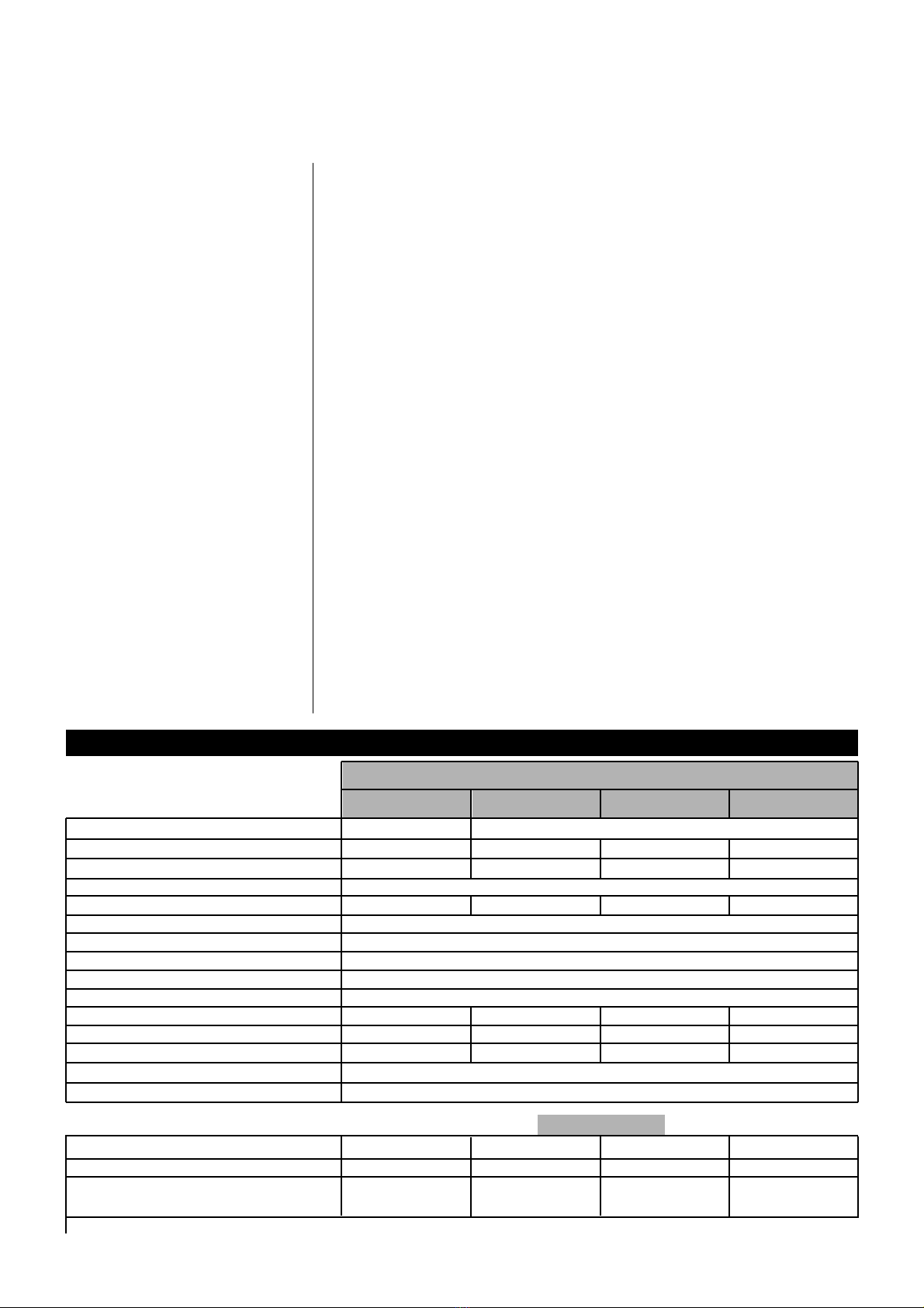
Technical specifications of
the ML-200-ST Central Unit
Applicator
I. 2
WARNING
GENERAL SPECIFICATIONS
• Central Unit Applicator with a highly performing piston pump with a wide range of
applications. Simple and manageable programming for all the outlet components.
• Series "standby ". This partial reduction in the temperature of the Central Unit
Applicator avoids early oxidation of the adhesive.
• Weekly program timer for the daily startup and shutdown of system as well as the
start-up and shutdown of the "standby".
• Simultaneous display of the programmed temperatures and real temperatures.
• Outlet for input electrical power at external power supply for Parent Machine
Interlock.
• Automatic detection of outlet connections.
• Complete safety system.
• Meets the CE/EML standards.
• Level monitor (optional).
• Inert gas injector for easily oxidated adhesives (optional).
• Use of 400 V current without neutral.
• Anti-moisture device for the series.
ELECTRONIC CONTROL
The operation and the globalized programming of the 200-ST Series is simple,
accurate and conceived to serve the user's convenience. The latest technological
advances in controls as well as in components of top grade quality have been used
to construct the electronic card in order to guarantee a dependable and lasting
performance.
Special protection against electronic noise.
It meets all the European EMC standards.
It has got digital display readout of all the heating areas, program timer, and
maintenance and alarm signals.
There are up to 13 areas of independent temperature control (depending on
model).
P.I.D. control with precision accuracy of set point temperature control.