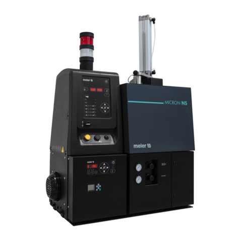
Meler Micron Mod User manual

ADHESIVE
MELTER
MICRON
MOD
INSTRUCTIONS
MANUAL
MA-5099-E 201016
GLUING SOLUTIONS

Published by:
Focke Meler Gluing Solutions, S.A
P.I. Los Agustinos, calle G, nave D-43
E - 31160 Orkoien Navarra (España)
Tel.: + 34 948 351 110
Fax: + 34 948 351 130
e-mail: info@meler.eu
www.meler.eu
A Focke Group Company
Edition October 2016
© Copyright by Focke Meler
All rights reserved. Its reproduction, diffusion or use by electronic or other
means of all or any part of this document without the express authorization of
its owner is strictly prohibited.
The specifications and information contained in this manual may be modified
without prior notice.
This manual is a translation of the original that was written by Focke Meler
Gluing Solutions, S. A in english language. If there is any discrepancy between
the different versions of this manual, the original written in the english
language shall prevail. Focke Meler Gluing Solutions, S. A shall not be liable
in any way for any damages and/or losses that may be directly or indirectly
derived from discrepancies between the original version of the manual and this
translation.

TABLE OF CONTENTS MA-5094-E MICRON MOD ADHESIVE MELTER MANUAL
TABLE OF CONTENTS
1. SAFETY GUIDELINES 1-1
General 1-1
Symbols 1-1
Mechanical components 1-2
Electrical components 1-2
Hydraulic components 1-2
Thermal components 1-2
Noise 1-3
Materials 1-3
2. INTRODUCTION 2-1
Description 2-2
Intended use 2-2
Limited use 2-2
Modes of operation 2-3
Hot-melt melter identification 2-3
Main components 2-4
Control card components 2-5
Optional equipment 2-6
Low-level warning light option 2-6
Automatic control option 2-6
Accessories 2-6
3. INSTALLATION 3-1
Introduction 3-1
Installation requirements 3-1
Electrical Consumption 3-2
Compressed air 3-2

TABLE OF CONTENTSFOCKE MELER GLUING SOLUTIONS
Other factors 3-2
Unpacking 3-3
Contents 3-3
Mounting the equipment 3-3
Electrical power connection 3-3
Pneumatic connection 3-4
Autoloader pneumatic connection 3-5
Suction tube connection 3-5
Connecting control detectors 3-6
Placing the suction tube 3-6
Hose and applicator connection 3-6
Parameter Programming 3-7
Programming working temperatures 3-7
Selecting the overheating value 3-8
Keeping a component on display 3-8
External I/O connections 3-9
Temperature ok 3-9
Output disabled 3-10
4. MELTER OPERATION 4-1
General information 4-1
Filling the adhesive 4-2
Starting up the melter equipment 4-2
Melter equipment displays 4-3
Displaying the temperature for each component 4-4
Alarm displays 4-4
Operational pressure display and adjustment 4-5
Temperature adjustment 4-6
Programming the applicator parameters 4-6
Setting the clock 4-8
Programming the current day and hour 4-8

TABLE OF CONTENTS MA-5094-E MICRON MOD ADHESIVE MELTER MANUAL
Programming equipment activation/deactivation 4-9
Disabling the equipment activation/deactivation program 4-10
Programming the equipment’s standby function activation/deactivation 4-10
Disabling the equipment standby function programming 4-11
Special function buttons 4-12
Start up and operation of the loader 4-13
Loader standby function 4-14
Single-colour or two-colour warning light 4-14
Level sensor adjustments 4-15
Sensitivity adjustment 4-15
Level stabilisation time 4-15
Programmable times using the timer 4-15
Disconnection delay time 4-15
Operating alarms 4-15
Change to standby time 4-16
Setting programmable times using the timer 4-16
Thermostat operation 4-17
Turning off the melter equipment 4-17
5. MAINTENANCE 5-1
Equipment cleaning 5-1
System depressurisation 5-2
Access to pneumatic unit 5-3
Pneumatic circuit 5-3
Pump filter maintenance 5-3
Cleaning the melter grid 5-4
Cleaning burnt adhesive 5-4
Safety Thermostat 5-5
Control of the load sensor 5-5
Inspection of the aspiration hose 5-6
Automatic feeder filter maintenance 5-6

TABLE OF CONTENTSFOCKE MELER GLUING SOLUTIONS
Control of pneumatic vibrator 5-6
Remove the equipment from its base 5-6
6. TROUBLESHOOTING 6-1
Melter 6-2
The unit does not turn on 6-2
Equipment shortcircuit malfunction 6-2
The equipment does not automatically go into standby 6-3
The equipment does not come out of standby into heating 6-3
The equipment does not load adhesive 6-3
Melter grid 6-4
The melter grid does not heat 6-4
The melter grid does not stop heating 6-4
Temperature fluctuations in the melter grid 6-5
Manifold 6-5
The manifold does not heat 6-5
The manifold does not stop heating 6-5
Temperature fluctuations in the manifold 6-6
Pump 6-6
The pump does not pump 6-6
Pneumatic unit 6-6
Pneumatic unit malfunction 6-6
Adhesive leaks 6-7
Hose 6-8
Hose does not heat 6-8
Hose does not stop heating 6-8
Temperature fluctuations in hose 6-8
Gun 6-9
Gun does not heat 6-9
Gun does not stop heating 6-9
Temperature fluctuations in gun 6-9

TABLE OF CONTENTS MA-5094-E MICRON MOD ADHESIVE MELTER MANUAL
7. TECHNICAL CHARACTERISTICS 7-1
Generals 7-1
Dimensions 7-2
Mounting the equipment 7-2
Optional equipment 7-2
Warning light option 7-2
VP option 7-2
8. ELECTRICAL DRAWINGS 8-1
9. PNEUMATIC DIAGRAM 9-1
Electro-pneumatic diagram for automatic feeder system 9-1
Component list 9-1
Pneumatic connection for 7 cm3/stroke PUMP 9-2
Components list 9-2
Pneumatic diagram for 7 cm3/stroke PUMP 9-3
Electro-pneumatic connection with pressure regulator VP. 7 cm3/stroke PUMP 9-4
Components list 9-4
Electro-pneumatic diagram with pressure regulator VP. 7 cm3/stroke PUMP 9-5
10. SPARE PARTS LIST 10-1
A. TANK ASSEMBLY 10-4
B. DISTRIBUTOR UNIT 10-5
C. PUMP ASSEMBLY 10-6
D. PNEUMATIC UNIT ASSEMBLY 7cc 10-7
E. CHASSIS ASSEMBLY 10-8
F. SUCTION TUBE AND VALVE ASSEMBLY 10-9
F. ELECTRIC/ ELECTRONIC ASSEMBLY 10-10
F. ELECTRIC/ ELECTRONIC ASSEMBLY 10-11
H. WARNING LIGHT AND VP-200 (OPTIONS) 10-12

TABLE OF CONTENTSFOCKE MELER GLUING SOLUTIONS
This page is intentionally left blank.

MA-5094-E MICRON MOD ADHESIVE MELTER MANUALSAFETY GUIDELINES
1-1
1. SAFETY GUIDELINES
General
The information contained in this section applies not only to everyday machine
operation, but also to any procedure carried out on it, whether for preventive
maintenance or in the case of repairs and the replacement of worn out parts.
It is very important to observe the safety warnings in this manual at all times.
Failure to do so may result in personal injury and/or damage to the machine
or the rest of the installation.
Before beginning work on the machine, read this manual carefully, and in case
of any doubt, contact our Technical Service Center. We are available for any
clarification that you might need.
Keep manuals in perfect condition and within reach of personnel that use the
machine and perform maintenance on it.
Also provide necessary safety material: appropriate clothing, footwear, gloves
and safety glasses.
In all cases, observe local regulations regarding risk prevention and safety.
Symbols
The symbols used on both the melter/applicator equipment and in this manual
always represent the type of risk we are exposed to. Failure to abide by a
warning signal may result in personal injury and/or damage to the machine or
the rest of the installation.
Warning: Risk of electrical shock. Carelessness may produce injury or death.
Warning: Hot zone with high temperatures. Risk of burns. Use thermal
protective equipment.
Warning: System under pressure. Risk of burns or particle projection. Use
thermal protective equipment and goggles.
Warning: Important information for the correct use of the system. May include
one or several of the previous hazards, and therefore must be kept in mind to
avoid damage and injury.

1-2
SAFETY GUIDELINESFOCKE MELER GLUING SOLUTIONS
Mechanical components
The melter/applicator equipment installation uses moveable parts that may
cause damage or injury. Use the equipment correctly, and do not remove the
safety guards while the equipment is in operation; prevent the risk of possible
entrapment due to moving mechanical parts.
Do not use the machine if the safety devices are not in place or appear to be
inadequately installed.
For maintenance or repair operations, stop the movement of moveable parts
by turning off the main switch.
Electrical components
The system operates with a one-phase current (LN ~ 230V 50Hz + PE or 3N ~
400/230V 50Hz+PE) at a certain rated power. Never handle the equipment with
the power connected, as this may result in powerful electrical shocks.
The installation must be correctly grounded.
The installation’s power cable conductors must match the required electric
current and voltage.
Periodically inspect the cables to check for crushing, wear and tear, as well as
to prevent tripping and falls as a result of their placement.
Although the system meets EMC requirements, it is inadvisable to use
devices that transmit high levels of radiation, i.e., mobile phones or soldering
equipment in their vecinity.
Hydraulic components
As this is a pressurized system, precautions related to this type of equipment
must be observed.
Before each operation, always make sure that the adhesive circuit is
completely free of pressure. There is a high risk of hot particle projection,
along with the corresponding danger of burns.
Use caution with the residual pressure that may remain in the hoses when the
adhesive cools. When reheated, there is a risk of hot particle projection if the
outputs are left open.
Thermal components
The entire system operates with temperatures reaching up to 200 °C (446
°F). The equipment must be operated using adequate protection (clothing,
footwear, gloves and protective glasses) that completely cover exposed parts
of the body.
Keep in mind that, due to the high temperatures reached, the heat does not
dissipate immediately, even when the power (in this case, electric) source is
disconnected. Therefore, use caution, even with the adhesive itself. It may
remain very hot, even in a solid state.

MA-5094-E MICRON MOD ADHESIVE MELTER MANUALSAFETY GUIDELINES
1-3
In case of burns, immediately cool the affected area with clean, cold water.
Seek medical attention as soon as possible from the company’s medical
service or the nearest hospital. Do not try to remove the adhesive material
from the skin.
Noise
The noise levels of the automatic feeder system is approximately 95 db, while
the automatic feeder is not working, the noise levels are below acceptable
levels, however, for operator safety we recommend working with individual
hearing protection.
Materials
Meler systems are designed for use with hot-melt adhesives. They should
not be used with any other type of material, and especially not with solvents,
which may cause personal injury or damage to internal system components.
Always use original Meler’ components and replacement parts, which
guarantee the correct system operation and service.
When using adhesive, follow the corresponding guidelines found in the
Technical and Safety Sheets provided by the manufacturer. Pay special
attention to the advised work temperatures in order to prevent adhesive
burning and degradation.
Ventilate the work area adequately in order to remove the vapors produced.
Avoid the prolonged inhalation of these vapors.

1-4
SAFETY GUIDELINESFOCKE MELER GLUING SOLUTIONS
This page is intentionally left blank.

MA-5094-E MICRON MOD ADHESIVE MELTER MANUALINTRODUCTION
2-1
2. INTRODUCTION
In this manual you will find information about the installation, use and
maintenance of the hot-melt adhesive melter in Meler’s Micron MOD.
This equipment is designed for applications with low-to-medium consumption
and on-demand adhesive melting.
One advantage of this equipment is its energy efficiency, as it uses electrical
energy to melt the adhesive and minimises energy losses to the outside
thanks to its improved insulation. Moreover, because it is a melt-on-demand
system, less energy is consumed during system start-up.
The equipment has an automatic pellet feeder that continuously supplies
adhesive to the equipment based on the application requirements, so that only
the adhesive that will be used is melted. The remaining adhesive is stored in
the original container at room temperature.
Each time the melter grid sensor detects a low adhesive level it sends a signal
to the suction system which load the adhesive directly from the adhesive bag
to the melter grid. The loading process is indicated by a light signal.
When the sensor detects the correct level again, the transfer of adhesive stops
(a disconnection delay can be programmed). An alarm system, timed from
the detection of low level, warns of possible flaws in the loading or completely
emptying the container for its replenishment.
The system activates a combined signal, noise and intermittent light. The
acoustic signal can be cancelled by the available button.
Once the alarm is corrected, the light signal turns off and the equipment is
restarted pushing the button ‘RESET’.

2-2
INTRODUCTIONFOCKE MELER GLUING SOLUTIONS
This instantaneous melting system guarantees optimum treatment of the
adhesive and prevents carbonisation and nozzle clogging, doing away with the
need for periodic cleaning.
The sealed loading system ensures there are no contaminating substances in
the adhesive circuit.
Description
The Micron MOD melters are designed for use with Meler hoses and
applicators in hot-melt adhesive applications. Their different variations –
line, coating or swirl-spray – cover a wide range of applications, being very
versatile in all markets where they are used.
Intended use
The hot-melt melters Micron MOD are designed to be used in the following
conditions:
• Hot-melt adhesive fusion and pumping at temperatures up to 200°C
(392°F).
• Use of hot-melt melters with Meler accessories.
• Installation of hot-melt melters according to the security regulations
currently in force and the instructions provided in this manual
(anchoring, electrical connection, hydraulic connection, etc).
• Use of hot-melt melters in non-explosive, non-chemically aggressive
environments.
• Use of hot-melt melters following the safety instructions indicated in
this manual, as well as on the labels accompanying the equipment,
using adequate means of protection during each mode of operation.
Limited use
The Micron MOD hot-melt melters must be used for their intended uses and
never in the following conditions:
• Use with reactive polyurethane- or polyamide-based adhesives or any
other material that might cause safety or health risks when heated.
• Use of hot-melt melters/applicators in environments where cleaning is
necessary using water jets.
• Use of hot-melt melters/applicators to heat or melt food products.
• Use or operation without adequate safety protection.
• Do not us it to transfer liquids or materials others than those specified.
Some adhesives can become sticky with moisture, causing a
malfunction of the device.

MA-5094-E MICRON MOD ADHESIVE MELTER MANUALINTRODUCTION
2-3
Modes of operation
The Micron MOD hot-melt melters may be used in all of the following modes:
Work mode_The hot-melt melter keeps materials hot at the pre-
selected temperature indicated on the display. The pump is kept
activated, waiting for the consumption command when one or more
application applicators are activated. The device operates normally,
loading the melter grid of the hot-melt system as often as low level the
detector of the loading system, installed on the melter grid, indicates
it. This corresponds to an automatic process where the operator should
not act on any element of control.
Standby mode_The hot-melt melter remains in a resting state, with
the materials kept at (programmable) temperature values below the
pre-selected value. The pump remains deactivated.
Alarm mode_The hot-melt melter/applicator detects a malfunction
and warns the operator of this event. The pump remains deactivated.
The device stops the function of load, stopping the expulsion of air,
in case the tube is obstructed or lack of adhesive in the adhesive
container. In this situation a light and an acoustic signal is emitted,
which can be overturned by the operator. After the intervention to
replenish the system, the operator must push the reset button. The
pump remains deactivated.
Stop mode_The hot-melt melter remains off, without heating the
materials and with the pump deactivated. The electrical and pneumatic
supply remains activated between the network and the system.
Hot-melt melter identification
When placing orders for replacement parts or requesting help from our
service center, you should know the model and reference number of your hot-
melt melter.
These data and other information of a technical nature can be located on the
identification plate located in the side part of the electrical cabinet.

2-4
INTRODUCTIONFOCKE MELER GLUING SOLUTIONS
Main components
1. Front control card
2. Access door to the electric/pneumatic area
3. Melter grid access lid to the reserve adhesive
4. Pump air pressure regulator
5. Air pressure gauge
6. Main switch
7. Hose output distributor (up to 6 hydraulic connections)
8. Hose-applicator electrical connections
9. Compressed air hook-up (Max. 6 bar)
10. Set of pump drain valve and filter
11. Automatic pellets adhesive feeder
12. Automatic feeder solenoid valve
13. Reset lighted button
14. Reset button to cancel acoustic signal
15. Pneumatic vibrator
16. Suction area
17. Flexible loading hose
10
11
12
87 9
6
4
5
1
13
14
15
17
16
23

MA-5094-E MICRON MOD ADHESIVE MELTER MANUALINTRODUCTION
2-5
Control card components
1. Melter grid indicator LED
2. Gun indicator LED
3. Temperature set point
4. Real temperature
5. ON/OFF switch
6. Standby function
7. Temperature OK LED
8. Time scheduling
9. Left/right button - channel selection
10. Up/down button - temperature modification
11. Hose indicator LED
1
2
3 4
7
8
6
5
11
10
9

2-6
INTRODUCTIONFOCKE MELER GLUING SOLUTIONS
Optional equipment
To increase the functionality of the melter machines, the following optional
elements can be incorporated:
Low-level warning light option
This warning light is an optional feature and you may choose between a
colourless low-level warning light (white) or a two-colour low-level warning
light (white) and temperature OK light (green).
Automatic control option
The VP-200 proportional valve system must be requested separately and
select between VP with or without connector.
Accessories
If some of the different machine configuration options have been chosen, it
will be necessary to purchase the following accessories separately:
• Adaptation plate for micron equipment. For adapting 4, 8 and 16l
equipment from the Micron line and the current 5, 10, and 20l Micron
equipment.

MA-5094-E MICRON MOD ADHESIVE MELTER MANUALINSTALLATION
3-1
3. INSTALLATION
Warning: The melters Micron MOD are equipment with current technology
and with certain foreseeable risks. Therefore, only allow qualified personnel
with sufficient training and experience to use, install or repair this equipment.
Introduction
The Micron MOD melters are delivered with all the materials necessary
for their installation. However, some components must be provided by the
user himself, according to the location and connections in each particular
installation:
• Anchoring screws for the melter/applicator equipment
• Power cord and plug for electrical power
• Pneumatic pipe and connection to the compressed air system
• Multicore cable for external electrical control
• Optionally, a gas ventilation system
Installation requirements
Before installing Micron MOD melter equipment, we must make sure that the
space assigned to it permits installing, connecting and using the entire system.
Similarly, we must check to see that the electrical and pneumatic supplies meet
the necessary requirements of the melter/applicator equipment being installed.
Free space
B
E
A
C
D

INSTALLATION
3-2
FOCKE MELER GLUING SOLUTIONS
Electrical Consumption
In order to install a Micron MOD melter, we should take into consideration
the total consumption of the installation, including the consumption of the
installed hoses and applicators.
Before connecting, make sure that the voltage that is being connected to
the melter/applicator is the correct one appearing on the equipment’s
characteristics plate.
Connect the machine and check to see if it is well grounded.
Warning: Risk of electrocution. Even when the equipment is turned off,
voltage remains in the intake terminals, which may be dangerous during
internal equipment manipulations.
Install a power switch for disconnecting the Micron MOD equipment from the
electrical network. It must be protected against overload and short circuits by
circuit breaker and install appropriate personal protection leads to mass by
differential switch.
Consumption figures, according to melter/applicator and output configuration,
are included in the table in the section ‘Electrical power connection’.
Compressed air
To install Micron MOD melters it is necessary to have a dry, non-lubricated
compressed air system with a maximum pressure of 6 bar.
The applicator’s internal pneumatic equipment is able to work with a
minimum of 0.5 bar, however, pressure lower than this will cause intermittent
operational anomalies.
The air consumption is according to the number of stroke made by the pump
cylinder, which in turn depends on the adhesive consumption during the
application. It is therefore necessary to estimate this consumption in all cases.
Generally speaking, we can provide as a maximum consumption value 40-50 l/min
for a pressure of 6 bar at maximum pump speed and only for the pneumatic unit.
Other factors
While installing Micron MOD melters other practical considerations should be
kept in mind:
Item Description Dimension
A EQUIPMENT LENGTH 587 mm
B EQUIPMENT WIDTH 341 mm
C EQUIPMENT WIDTH HEIGHT 481 mm
D EQUIPMENT HEIGHT WITH AUTOMATIC FEEDER (APROX.) 577 mm
EEQUIPMENT LENGTH WITH ELECTRICAL CABINET
DESPLACED 838 mm
Table of contents
Other Meler Industrial Equipment manuals

Meler
Meler Micron Gear Series User manual

Meler
Meler MACRO FOAM Series User manual

Meler
Meler PS20 User manual

Meler
Meler PS200 User manual

Meler
Meler PS 20 NON STOP+ User manual

Meler
Meler SF10 User manual

Meler
Meler MICRON+ GEAR Series User manual

Meler
Meler Micron PUR LC User manual

Meler
Meler MICRON NON STOP User manual

Meler
Meler B4 NON-STOP User manual