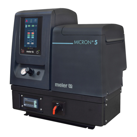
Meler Micron 5 User manual

ADHESIVE
AUTOMATIC
FEEDER
INSTRUCTIONS
MANUAL
MA-5048-ENG 271118
GLUING SOLUTIONS

Published by:
Focke Meler Gluing Solutions, S. A.
P.I. Los Agustinos, calle G, nave D-43
E - 31160 Orkoien Navarra (España)
Tel.: + 34 948 351 110
Fax: + 34 948 351 130
e-mail: info@meler.eu
www.meler.eu
A Focke Group Company
Edition November 2018
© Copyright by Focke Meler
All rights reserved. Its reproduction, diffusion or use by electronic or other
means of all or any part of this document without the express authorization of
its owner is strictly prohibited.
The specifications and information contained in this manual may be modified
without prior notice.
This manual is a translation of the original that was written by Focke Meler
Gluing Solutions, S. A. in spanish language. If there is any discrepancy between
the different versions of this manual, the original written in the spanish
language shall prevail. Focke Meler Gluing Solutions, S. A. shall not be liable
in any way for any damages and/or losses that may be directly or indirectly
derived from discrepancies between the original version of the manual and this
translation.

MA-5048-ENG ADHESIVE AUTOMATIC FEEDERTABLE OF CONTENTS
TABLE OF CONTENTS
1. SAFETY GUIDELINES 1-1
General 1-1
Symbols 1-1
Mechanical components 1-2
Electrical components 1-2
Hydraulic components 1-2
Pneumatic components 1-2
Thermal components 1-3
Materials 1-3
Noise emission declaration 1-3
Intended use 1-4
Limited use 1-4
2. INTRODUCTION 2-1
Description 2-1
Operation modes 2-2
Identification of the hot melt system 2-2
Main components 2-3
General 2-3
50 kg container 2-4
50 kg container settings 2-5
3. INSTALLATION 3-1
Preliminaries 3-1
Installation requirements 3-1
Electrical Consumption 3-2
Compressed air 3-2

FOCKE MELER GLUING SOLUTIONS TABLE OF CONTENTS
Unpacking 3-2
Content 3-2
Feeder assembly 3-3
Pneumatic connection 3-3
Suction tube connection 3-4
Connecting control detectors 3-4
Installation of external control box 3-4
Connection of signals for standby function 3-5
Pellet container installation 3-5
Electrical power supply connections 3-5
Container with reset button 3-5
Container with pellet level control 3-6
Placing the suction tube 3-6
4. USE OF THE UNIT 4-1
Start up and automatic process 4-1
Sensor adjustments 4-2
Sensitivity adjustment 4-2
Positioning of the level sensor 4-2
Level stabilisation time 4-3
Programmable times using the timer 4-3
Disconnection delay time 4-3
Operating alarms 4-3
Change to standby time 4-4
Setting programmable times using the timer 4-4
Manual feeding 4-5
Pellet container level sensor 4-5
5. MAINTENANCE 5-1
Cleaning of the unit 5-1
Pneumatic system 5-1

MA-5048-ENG ADHESIVE AUTOMATIC FEEDERTABLE OF CONTENTS
Control of the load sensor 5-2
Inspection of the aspiration tube 5-2
Filter maintenance 5-2
Control of pneumatic vibrator 5-2
6. TECHNICAL CHARACTERISTICS 6-1
General 6-1
7. ELECTRICAL DRAWINGS 7-1
8. PNEUMATIC DIAGRAM 8-1
9. SPARE PARTS 9-1
A. ELECTRICAL COMPONENTS OF THE CONTROL BOARD 9-2
B. SUCTION TUBE 9-4
C. VALVE ASSEMBLY 9-5
D. FILTER- SENSOR ASSEMBLY 9-6

FOCKE MELER GLUING SOLUTIONS TABLE OF CONTENTS
This page is intentionally left blank.

MA-5048-ENG ADHESIVE AUTOMATIC FEEDERSAFETY GUIDELINES
1-1
1. SAFETY GUIDELINES
General
The information contained in this section applies not only to everyday
equipment operation, but also to any procedure carried out on it, whether for
preventive maintenance or in the case of repairs and the replacement of worn
out parts.
It is very important to observe the safety warnings in this manual at all times.
Failure to do so may result in personal injury and/or damage to the equipment
or the rest of the installation.
Before beginning work on the equipment, read this manual carefully, and in
case of any doubt, contact our Technical Service Center. We are available for
any clarification that you might need.
Keep manuals in perfect condition and within reach of personnel that use the
equipment and perform maintenance on it.
Also provide necessary safety material: appropriate clothing, footwear, gloves
and safety glasses.
In all cases, observe local regulations regarding risk prevention and safety.
Symbols
The symbols used on both the melter/applicator equipment and in this manual
always represent the type of risk we are exposed to. Failure to abide by a
warning signal may result in personal injury and/or damage to the equipment
or the rest of the installation.
Warning: Risk of electrical shock. Carelessness may produce injury or death.
Warning: Hot zone with high temperatures. Risk of burns. Use thermal
protective equipment.
Warning: System under pressure. Risk of burns or particle projection. Use
thermal protective equipment and glasses.
Warning: Important information for the correct use of the system. May include
one or several of the previous hazards, and therefore must be kept in mind to
avoid damage and injury.
Warning: Dangerous area. Risk of entrapment. Carelessness may produce
injury or death.

FOCKE MELER GLUING SOLUTIONS
1-2
SAFETY GUIDELINES
Mechanical components
The hot-melt installation, which is installed to this device, requires moving
parts that can cause damage. Use the equipment correctly, and do not remove
the safety guards while the equipment is in operation; prevent the risk of
possible entrapment due to moving mechanical parts.
Do not use the equipment if the safety devices are not in place or appear to be
inadequately installed.
For maintenance or repair operations, stop the movement of moveable parts
by turning off the main switch.
The device has no moving mechanical parts, so it does not pose risks to
consider in this section.
Electrical components
The system works with single-phase or three-phase current of a certain
power. Never handle the equipment with the power connected, as this may
result in powerful electrical shocks.
The installation must be correctly grounded.
The installation’s power cable conductors must match the required electric
current and voltage.
Periodically inspect the cables to check for crushing, wear and tear, as well as
to prevent tripping and falls as a result of their placement.
Although the system meets EMC requirements, it is inadvisable to use
devices that transmit high levels of radiation, i.e., mobile phones or soldering
equipment in their vecinity.
Hydraulic components
As this is a pressurized system, precautions related to this type of equipment
must be observed.
Before each operation, always make sure that the adhesive circuit is
completely free of pressure. There is a high risk of hot particle projection,
along with the corresponding danger of burns.
Use caution with the residual pressure that may remain in the hoses when the
adhesive cools. When reheated, there is a risk of hot particle projection if the
outputs are left open.
Pneumatic components
Some equipment uses compressed air to 6 bar pressure. Before any
manipulation, please ensure that the circuit has lost fully air pressure. The
risk of projection of particles at high speed can cause injury to a certain
severity.
Extreme precautions with the residual pressure that could be contained in the
circuit, before disconnecting any pneumatic feeding tube.

MA-5048-ENG ADHESIVE AUTOMATIC FEEDERSAFETY GUIDELINES
1-3
Thermal components
The entire system works with temperatures that can exceed 200°C (336°F).
The equipment must be operated using adequate protection (clothing,
footwear, gloves and protective glasses) that completely cover exposed parts
of the body.
Keep in mind that, due to the high temperatures reached, the heat does not
dissipate immediately, even when the power (in this case, electric) source is
disconnected. Therefore, use caution, even with the adhesive itself. It may
remain very hot, even in a solid state.
In case of burns:
1. If the burn is the result of contact with melted adhesive, do not try to
remove the adhesive material from the skin. Do not try to remove it once
it has solidified either.
2. Cool the affected area down immediately with lots of cold and clean water.
3. Seek medical attention as soon as possible either from the company’s
medical service or the nearest hospital. Provide the medical staff with the
Safety Information Sheet of the adhesive.
Materials
Meler systems are designed for use with hot-melt adhesives. They should
not be used with any other type of material, and especially not with solvents,
which may cause personal injury or damage to internal system components.
Some units are specifically designed to use polyurethane reactive (PUR) hot-
melt adhesives. Using PUR on a unit that is not prepared for that purpose may
cause severe damage to the unit.
When using adhesive, follow the corresponding guidelines found in the
Technical and Safety Sheets provided by the manufacturer. Pay special
attention to the advised work temperatures in order to prevent adhesive
burning and degradation.
Ventilate the work area adequately in order to remove the vapors produced.
Avoid the prolonged inhalation of these vapors.
Always use original Meler components and replacement parts, which
guarantee the correct system operation and service.
Noise emission declaration
The A-weighted emission sound pressure level (LpA) of the unit in operation
does not exceed 70 dB(A) under any circumstances.
The maximum C-weighted sound pressure level (LpCpeak) and the A-weighted
sound power level (LWA) do not exceed values worthy of mention and thus do
not represent a specific risk that must be taken into account.

FOCKE MELER GLUING SOLUTIONS
1-4
SAFETY GUIDELINES
Intended use
The hot-melt melters in the Macro Foam series are designed to be used in the
following conditions:
• Hot-melt adhesive fusion and pumping at temperatures up to 180 °C
(356 ºF). Consult with Meler technical service to operate with higher
working temperatures.
• Use of hot-melt melters with Meler accessories.
• Installation of hot-melt melters according to the security regulations
currently in force and the instructions provided in this manual
(anchoring, electrical connection, hydraulic connection, etc).
• Use of hot-melt melters in non-explosive, non-chemically aggressive
environments.
• Use of hot-melt melters following the safety instructions indicated in
this manual, as well as on the labels accompanying the equipment,
using adequate means of protection during each mode of operation.
Limited use
The unit should never be used under the following conditions:
• Use with reactive polyurethane or any other material that might cause
safety or health risks when heated.
• Use of hot-melt melters in environments where cleaning is necessary
using water jets.
• Use of hot-melt melters to heat or melt food products.
• In potentially explosive atmospheres, aggressive chemical
environments or outdoors.
• Use or operation without adequate safety protection.
• If the person in question does not have the necessary training to use
the unit or to apply all of the necessary safety measures.
Note: Do not modify the unit or use components that were not supplied by Me-
ler. For any modification of a component of the unit or part of the installation,
you must firstly consult the After-Sales Service

MA-5048-ENG ADHESIVE AUTOMATIC FEEDERINTRODUCTION
2-1
2. INTRODUCTION
Description
The Meler adhesive automatic feeder ensures a continuous level of adhesive
inside the melting tanks, eliminating the task of manually refilling by the user.
Each time the tank sensor detects a low adhesive level it sends a signal to
the suction system which, from the container adhesive (or directly from the
adhesive bag), transferred a load of adhesive to the melting tank. The loading
process is indicated by a light signal.
When the sensor detects the correct level again, the transfer of adhesive stops
(a disconnection delay can be programmed).
An alarm system, timed from the detection of low level, warns of
possible flaws in the loading or completely emptying the container for its
replenishment.
The system triggers a combined signal, noise and intermittent light. The
acoustic signal can be cancelled by the available button.
Once corrected incidence signal light turns off the unit by ‘RESET’ button.
The system provides a level of security in the hot-melt cast within the fuser
team, as well as the absence of charred material (the adhesive is melting and
contributing as it needs), prevents external contamination of the adhesive (in a
totally enclosed system ) and facilitates the tasks of recharge.

FOCKE MELER GLUING SOLUTIONS
2-2
INTRODUCTION
The unit can be installed in the range of Meler hot-melt tanks, as well as other
units on request.
It supplies the unit load (control, filter, sensors and aspiration mouth suction),
together with some specific adaptation to the requested unit.
As an accessory, the system features a container for the adhesive with a
capacity of 50 kg, with the aim of providing the system with greater autonomy.
This container can also feature its own level control, which operates in the
same way as the melter.
Do not us it to transfer liquids or materials others than those specified. Some
adhesives can become sticky with moisture, causing a malfunction of the
device.
Operation modes
The automatic feeder has the following service statuses:
Loading mode_The device operates normally, loading the tank of
the hot-melt system as often as low level the detector of the loading
system, installed on the tank, indicates it. This corresponds to an
automatic process where the operator should not act on any element of
control.
This mode can also have the ‘standby’ activation function of the melter
enabled. When the melter (at temperature OK and adhesive tank level
OK) does not request pellet feeding after a programmable period of
time has passed, the feeder control puts the melter into ‘standby’
mode.
Alarm mode_The device stops the function of load, stopping the
expulsion of air, in case the tube is obstructed or lack of adhesive in
the adhesive container. In this situation a light and an acoustic signal is
emitted, which can be overturned by the operator. After the intervention
to replenish the system, the operator must push the RESET button.
Inhibition mode_ The automatic loading stops but operator can done
manual loads without control by the level detector so there is a risk of
overflow.
Stop mode_The device in off stays without tension.
It does not signal any load control. However, the system keeps the air
pressure in the input circuit.
Identification of the hot melt system
When you want to place orders for parts or materials or if you request support
from our Technical Service you should indicate the reference and serial
number of your equipment.
These data and other information of a technical nature can be located on the
identification plate on the electrical control box.

MA-5048-ENG ADHESIVE AUTOMATIC FEEDERINTRODUCTION
2-3
Main components
General
19 18 17
1
2
3
16
15
14
65 7 8
12
11
10
13
9
4
1. Flexible Load Tube
2. Rotary fitting
3. Unload Filter
4. Load Sensor
5. Control Board
6. Output air supply to the suction area
7. Electric load valve
8. Input air supply (from the grid)
9. Led for activation of load sensing
10. Sensitivity adjustment of load sensor
11. Sensor Connectors
12. Sensor closed lid
13. Connector power supply
14. Main switch
15. Reset button for acoustic signal
16. Illuminated rearmament button
17. Pneumatic vibrator
18. Suction area
19. Air feeding tube

FOCKE MELER GLUING SOLUTIONS
2-4
INTRODUCTION
50 kg container
1. 50 kg container
2. Flexible feeding duct
3. Pellet inlet screen
4. Control Board container
5. Reset button for acoustic signal
6. Illuminated rearmament button
7. Main switch
8. Connector power supply
9. Sensitivity adjustment of load sensor
10. Led for activation of load sensing
11. Pellet level sensor in container (optional)
12. Pneumatic vibrator
13. Suction area
14. Air feeding tube (optional for 1 or 2 units)
15. Air inlets towards the suction port
16. Lit reset button sensor melter (optional)
9
10
11
12
13
14
8
16
765
4
3
1
2
15

MA-5048-ENG ADHESIVE AUTOMATIC FEEDERINTRODUCTION
2-5
50 kg container settings
• Basic pellet storage container 1 upper outlet.
• Pellet storage container 1 rear outlet.
• Pellet storage container 2 rear outlets.
• Pellet storage container 1 rear outlet with RESET button for melter.
• Pellet storage container 2 rear outlets with RESET button for melters.
• Pellet storage container 1 rear outlet with level sensor. (*)
• Pellet storage container 2 rear outlets with level sensor. (*)
(*) The level sensor RESET button can be associated with the RESET button of the melters.

FOCKE MELER GLUING SOLUTIONS
2-6
INTRODUCTION
This page is intentionally left blank.

MA-5048-ENG ADHESIVE AUTOMATIC FEEDERINSTALLATION
3-1
3. INSTALLATION
Warning: The vacuum feeders are installed in equipment with updated
technology with foreseeable risks. Therefore, you should allow only the
access to skilled people, with sufficient training and experience in handling,
installation or repair of such equipment.
Preliminaries
The feeder is normally supplied together with the melter unit, with the
elements necessary for installation and use. However, some components must
be supplied by the user depending on the location and connections of each
facility including:
• Power cable for power supply
• Tube for compressed air and connector
• Appropriate and closed container for the adhesive
Installation requirements
Before installing or using a vacuum feeder we must ensure that the space for
it allows the location, connection and use of the entire system. We must also
ensure that the electrical and pneumatic supplies meet the requirements
demanded by the used device.
APROBACION
Ing. FabricaciónCalidad Producción
Nombre:
Nombre: Nombre:
MANTENER ORDEN Y LIMPIEZA
EN EL PUESTO Y
EN LA LINEA EN GENERAL
GUANTES
ZAPATOS
GAFAS
OTROS
EQUIPO
DE SEGURIDAD
Formación requerida
operario
Nºde Pokayokes
Piezas en proceso
Calibración requerida
90
100
660
195
410
340
Standard length 4 m
MGB 120
480
441
270°
875
927
480
355
543
MGB 120
480
441
270°
875
927
480
355
543

FOCKE MELER GLUING SOLUTIONS INSTALLATION
3-2
Electrical Consumption
Before connecting the vacuum feeder we must take into account the total
consumption of the system and provide an appropriate power supply.
Check nameplate of the feeder before the connection, in order to connect
device to the appropriate voltage.
Connect and ensure a correct grounding of the device.
Warning: Risk of electrocution. Even when the equipment is turned off, voltage
remains in the intake terminals, which may bedangerous during internal
equipment manipulations.
The control panel of the feeder incorporates a general OFF switch that
insulates the unit of its power supply. This protects against short circuits
through a fuse with external access to it, but you must protect the entire
installation from the power supply against overloads. Install a power switch
for disconnecting the melter/applicator equipment from the electrical
network.
The power associated with this protection is indicated on the nameplate of the
feeder.
Compressed air
To install ‘meler’ vacuum feeder, it is necessary to have a dry, non-lubricated
compressed air system with a maximum pressure of 6 bars.
The air inlet pipe is installed to 10 mm outer diameter.
Unpacking
Before proceeding with the installation of the vacuum feeder, it should be
removed from its location on a pallet and examined in order to detect any
possible breakage or deterioration.
Communicate any defect, even to the outer packing materials, to your ‘meler’
Representative or to the Main Office.
Content
If the feeder has been issued installed on a hot-melt system, all elements
of the system are mounted on it, except the suction tube which should be
connected to the swivel connector.
If the system has a pellet container with reset button, also including a feeding
system and/or level sensor, all of the necessary components in the container
will come already mounted.

MA-5048-ENG ADHESIVE AUTOMATIC FEEDERINSTALLATION
3-3
Feeder assembly
If the vacuum feeder installed on an existing melter please follow the
correspondent instructions for each model of meler unit.
Warning: Ensure that the earth cable of the sensor has been connected to the
ground connection of the melter.
Electrical power supply connections
The vacuum feeder is supplied to be connected to the power supply of single
phase 230 VAC, depending on their power consumption.
It is always imperative to install a good ground connection.
The maximum and minimum values are listed on the nameplate of the system.
Warning: Risk of electrical shock. Carelessness may produce injury or death.
Connect and fix the power cable (3x0.75mm2) to the supplied plug.
Connect the plug to the control box fixing it with the metal clamp.
Connect the other end of the power cable to the power socket.
Pneumatic connection
Before connecting the pneumatic power to the vacuum feeder, make sure
the pressure regulator on the system and the main air supply is completely
closed.
Connect the vacuum feeder through a flexible tube with outside diameter of 10
mm to the general air supply (6 bar max.) (1). The unit has a quick coupling for
this connection.
The air outlet grid (2) is connected by a flexible hose outside diameter 10 mm
to the Y quick connector (3) located in the area of the suction adhesive.
To be sure about the connection of the tubes in the inlet and the outlet, the
valve is marked with the numbers 1 and 2 respectively. See the pictures.
Once connected, open the air supply verify that you have maximum 6 bar
pressure. Pressures higher than that causes an unnecessary expense and
the possibility to produce turbulences in the hot melt tank with consequent
malfunction of the unit.
3
1
2

FOCKE MELER GLUING SOLUTIONS INSTALLATION
3-4
Suction tube connection
The suction tube should be connected to the swievel elbow of the vacuum
feeder, inserting it into the inside of the metallic mouth down to its bottom.
Place the swievel elbow to the most convenient position for installation,
depending on the location of the hot melt container.
Therefore:
• Loose slightly the three fixing screws for the lid of the filter and set
the swievel elbow.
• Place the swievel elbow to the desired position, twisting it in the
required sense.
• Tight the three fixing screws to the position of the elbow and prevent
their movement.
Connecting control detectors
The vacuum feeder has two control sensors for the control of the operation of
the system.
The low level sensor detects a low level of adhesive in the tank, in order to
activate the filling of adhesive and when it has reached the right level to stop
this filling.
The “lid closed” detector allows the stop the filling procedure when the lid is
opened, preventing the projection of adhesive to the outside.
Both sensors are wired in a single connector at the control box. This
connection allows the installation of the control box away from the hot melt
tank using an appropriate interconnection cable.
Installation of external control box
In some situations, it will be necessary to place the control box away from the
hot melt equipment. It should be taken into account, that the longer the air
and the vacuum tubes are, the suction force will be reduced.
In order to bring the control box and the air supply closer to the adhesive
container, you can install the control box away from the hot melt equipment
and closer to the mouth of the suction tube.
Therefore take into account the following factors:
- Location and setting of the control box
- Electric connections of the sensors
The control box, with the solenoid valve incorporated, is fixed with two screws
to the provided squadron, following the attached drawing. On demand ‘meler’
will supply this squadron.
For the electrical connection, an interconnection extension cable between the
electrical box and the plug of the installed sensors on the hot melt system is
required.
MATERIAL/MATERIAL
TRATAMIENTO/
TREATMENT
VALIDADO/COMFIRMDIBUJADO/DESIGN
NOMBRE/NAME
FECHA/DATE
TITULO/TITLE
ESCALA/SCALE
REFERENCIA/
REFERENCE
SUS. A/
REPLACES
CATEGORIA/
RATE
DENOMINACION/DENOMINATION
HOJA Nº/
SHEET NUMBER
I.A.A.
17/02/2014 17/02/2014
J.Z.G.
2:3 515503881
SOPORTE PARED CARGADOR DE GRANZA 2014 P. GRIS
ANTR
1 de 1 SECUNDARIA
S275JR
Pintado Gris Ral 7016
Texturado
Este plano es propiedad exclusiva de MELER APLICADORES DE HOT - MELT S.A. Todos los derechos reservados.
This drawing is owned sole of MELER APLICADORES DE HOT- MELT S.A. All rights reserved.
DPTO. OFICINA TECNICA
515503880
REV./
REV.
-----
-
-----
30
60
87 6,5
R4
R4
12
260 15
53
100
0.5 ≤33 ≤6 6 ≤ 30 30 ≤120 120 ≤ 400 400 ≤ 1000 1000 ≤ 2000
±0.1 ±0.1 ±0.2 ±0.3 ±0.5 ±0.8 ±1.2
Radios y alturas de chaflán/Radius and chamfer heigh(mm)
±0.2
0.5 ≤3 3 ≤6 6 <
±0.5 ±1
Dimensiones angulares/Angular dimensions
≤10 10 ≤ 50 50 ≤120 120 ≤400 400 <
±1º±0º30´0º20´0º10´0º5´
ISO 2768-1 MEDIUM GRADE Dimensiones lineales/lineal dimensions except broken edges (mm)
86,52
100
6,52 Aguj.
2 Aguj. M6x1
VISTA DESARROLLO
DESARROLLO: Atención, el desarrollo es sólo orientativo,
no es válido para la fabricación de la pieza
27/02/14 Se reduce el espesor de chapa a 2mm I.A.A.
IDENT FECHA/DATE MODIFICACIÓN/CHANGE
1
APROBADO/CONFIRM
REALIZADO/DESIGN
J.Z.G.
Nota: Las cotas indicadas en el plano son después del tratamiento. A todas las cotas con tolerancia se les debe aplicar corrección de medida
acorde al tratamiento indicado en el plano.
Note: The dimensions shown in the drawing are after treatment. In all dimensions with tolerance they should be applied according to treatment
indicated on the map.
Other manuals for Micron 5
3
Table of contents
Other Meler Laboratory Equipment manuals
Popular Laboratory Equipment manuals by other brands

Belden
Belden HIRSCHMANN RPI-P1-4PoE installation manual

Koehler
Koehler K1223 Series Operation and instruction manual

Globe Scientific
Globe Scientific GCM-12 quick start guide

Getinge
Getinge 86 SERIES Technical manual

CORNING
CORNING Everon 6000 user manual

Biocomp
Biocomp GRADIENT MASTER 108 operating manual