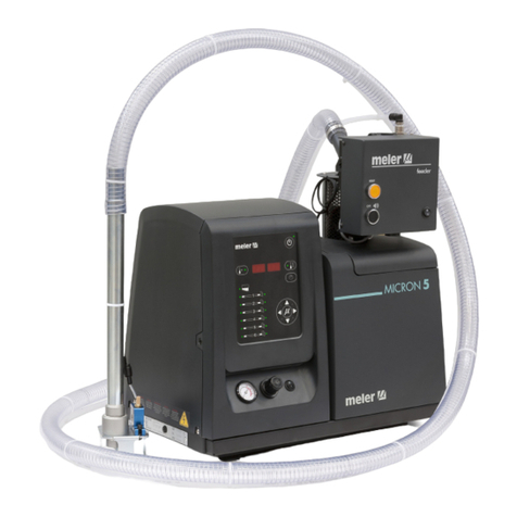
Meler PS 20 NON STOP+ User manual

GLUING SOLUTIONS
MA-5060-GBR 210220
ADHESIVE
MELTER
PS20
NON STOP
INSTRUCTIONS
MANUAL

Published by:
Focke Meler Gluing Solutions, S.A.
Pol. Arazuri-Orkoien, c/B, nº3 A
E-31170 Arazuri - Navarra - Spain
Phone: +34 948 351 110
info@meler.eu - www.meler.eu
A Focke Group Company
Edition February 2020
© Copyright by Focke Meler
All rights reserved. Its reproduction, diffusion or use by electronic or other
means of all or any part of this document without the express authorization of
its owner is strictly prohibited.
The specifications and information contained in this manual may be modified
without prior notice.
This manual is a translation of the original that was written by Focke Meler
Gluing Solutions, S. A in spanish language. If there is any discrepancy between
the different versions of this manual, the original written in the spanish
language shall prevail. Focke Meler Gluing Solutions, S. A shall not be liable
in any way for any damages and/or losses that may be directly or indirectly
derived from discrepancies between the original version of the manual and this
translation.

TABLE OF CONTENTS MA-5060-GBR PS20 NON STOP DRUM UNLOADER MANUAL
TABLE OF CONTENTS
1. SAFETY GUIDELINES 1-1
General 1-1
Symbols 1-1
Mechanical components 1-2
Electrical components 1-2
Hydraulic components 1-2
Pneumatic components 1-2
Thermal components 1-3
Materials 1-3
Noise emission declaration 1-3
Intended use 1-4
Limited use 1-4
2. INTRODUCTION 2-1
Description 2-2
Intended use 2-2
Limited use 2-2
Modes of operation 2-2
Identifying the melting equipment 2-3
Main components 2-4
Optional equipment 2-6
Pneumatic by-pass valve pressure control system (VP) 2-6
Double pressure solenoid valve control system (DP) 2-7
3. INSTALLATION 3-1
Introduction 3-1
Installation requirements 3-1
Free space 3-1
Electrical Consumption 3-2
Compressed air 3-2
Other factors 3-3
Unpacking 3-3

FOCKE MELER GLUING SOLUTIONS TABLE OF CONTENTS
Contents 3-3
Mounting the equipment 3-3
Electrical power connection 3-4
Pneumatic connection 3-4
Hose and applicator connection 3-5
External I/O connections 3-5
Temperatures ok 3-6
External ON/OFF 3-7
External Standby 3-7
Low level (optional) 3-7
ON/OFF Status 3-8
Adhesive bag nealy empty 3-8
Adhesive bag empty 3-9
Alarm Status 3-9
Motor start up 3-9
Motor speed set point reference 3-10
Failures output in the inverter 3-10
4. TOUCH SCREEN NAVIGATION 4-1
Equipment configuration 4-7
Parameters 4-7
1. Overtemperature 4-7
2. Standby 4-7
3. Activation standby because of motor OFF 4-8
4. Timeout to start pumping 4-8
5. Air injection time 4-9
6. Timeout air injection 4-9
7. Alarm time in the air injection 4-10
8. Volume delivered 4-10
9. Timeout 4-11
10. Pump data 4-11
Programming the time 4-12
1. Programming current day and hour 4-12
2. Programming activation / deactivation equipment 4-13
3. Programming activation / deactivation standby function 4-14

TABLE OF CONTENTS MA-5060-GBR PS20 NON STOP DRUM UNLOADER MANUAL
Example of Programming for activation, deactivation and standby 4-15
Setting the security password 4-16
Set working temperature 4-17
Pumping speed control 4-19
Select signal “INTERNAL” 4-21
Select signal “EXTERNAL“ 4-21
By-pass valve regulation 4-23
Manual valve control 4-23
Pneumatic valve control 4-23
Switch off the melter 4-24
Using the air dry system 4-24
Injection cycle 4-24
Regulating pushing pressure 4-25
5. MELTER OPERATION 5-1
General information 5-1
Filling the tank 5-2
Starting up the melter equipment 5-3
Alarm displays 5-5
Premelting activating 5-6
Premelting and gas injection activation 5-6
Gas injection 5-7
6. MAINTENANCE 6-1
Equipment cleaning 6-1
Depressurizing the system 6-2
Cleaning the tank 6-2
Changing adhesive type 6-2
Cleaning burnt adhesive 6-3
Emptying the tank 6-3
Cleaning the bottom tank 6-4
Cleaning the platten 6-6
Cleaning the capacitive sensor 6-8
Sensitivity adjustment of the capacitive sensor 6-8
Verification of the sensor regulation 6-9

FOCKE MELER GLUING SOLUTIONS TABLE OF CONTENTS
Pump maintenance 6-10
Inspecting for leaks 6-10
Motor-gear maintenance 6-10
Cleaning the motor fan 6-10
Checking the lubricant 6-10
Recommended lubricants 6-11
Thermostats maintenance 6-11
Air dryer filter maintenance 6-12
7. TECHNICAL CHARACTERISTICS 7-1
Generals 7-1
Dimensions 7-2
Accesories 7-2
Pneumatic by-pass valve pressure control system 7-2
Light tower system 7-2
Air drying system for PUR adhesives 7-3
8. ELECTRICAL DRAWINGS 8-1
9. PNEUMATIC DRAWING 9-1
Components list 9-1
Pneumatic by-pass valve pressure control system (VP) 9-3
Double pressure solenoid valve control system (DP) 9-3
10. SPARE PARTS LIST 10-1
A. COVER ASSEMBLY 10-3
B. TANK GROUP 10-4
C. DISTRIBUTOR GROUP 10-5
D. FILTER AND PRESSURE VALVE GROUP 10-6
E. MOTOR-PUMP GROUP 10-7
F. ELECTRICAL CABINET 10-8
G. PNEUMATIC GROUP 10-11
H. AIR DRYER GROUP (OPTIONAL) 10-12
EC DECLARATION OF CONFORMITY 11-1

SAFETY GUIDELINES
1-1
MA-5060-GBR PS20 NON STOP DRUM UNLOADER MANUAL
1. SAFETY GUIDELINES
General
The information contained in this section applies not only to everyday
equipment operation, but also to any procedure carried out on it, whether for
preventive maintenance or in the case of repairs and the replacement of worn
out parts.
It is very important to observe the safety warnings in this manual at all times.
Failure to do so may result in personal injury and/or damage to the equipment
or the rest of the installation.
Before beginning work on the equipment, read this manual carefully, and in
case of any doubt, contact our Technical Service Center. We are available for
any clarification that you might need.
Keep manuals in perfect condition and within reach of personnel that use the
equipment and perform maintenance on it.
Also provide necessary safety material: appropriate clothing, footwear, gloves
and safety glasses.
In all cases, observe local regulations regarding risk prevention and safety.
Symbols
The symbols used on both the melter/applicator equipment and in this manual
always represent the type of risk we are exposed to. Failure to abide by a
warning signal may result in personal injury and/or damage to the equipment
or the rest of the installation.
Warning: Risk of electrical shock. Carelessness may produce injury or death.
Warning: Hot zone with high temperatures. Risk of burns. Use thermal
protective equipment.
Warning: System under pressure. Risk of burns or particle projection. Use
thermal protective equipment and glasses.
Warning: Important information for the correct use of the system. May include
one or several of the previous hazards, and therefore must be kept in mind to
avoid damage and injury.
Warning: Dangerous area. Risk of entrapment. Carelessness may produce
injury or death.

FOCKE MELER GLUING SOLUTIONS
1-2
SAFETY GUIDELINES
Mechanical components
The hot-melt installation, which is installed to this device, requires moving
parts that can cause damage. Use the equipment correctly, and do not remove
the safety guards while the equipment is in operation; prevent the risk of
possible entrapment due to moving mechanical parts.
Do not use the equipment if the safety devices are not in place or appear to be
inadequately installed.
For maintenance or repair operations, stop the movement of moveable parts
by turning off the main switch.
The device has no moving mechanical parts, so it does not pose risks to
consider in this section.
Electrical components
The system works with single-phase or three-phase current of a certain
power. Never handle the equipment with the power connected, as this may
result in powerful electrical shocks.
The installation must be correctly grounded.
The installation’s power cable conductors must match the required electric
current and voltage.
Periodically inspect the cables to check for crushing, wear and tear, as well as
to prevent tripping and falls as a result of their placement.
Although the system meets EMC requirements, it is inadvisable to use
devices that transmit high levels of radiation, i.e., mobile phones or soldering
equipment in their vecinity.
Hydraulic components
As this is a pressurized system, precautions related to this type of equipment
must be observed.
Before each operation, always make sure that the adhesive circuit is
completely free of pressure. There is a high risk of hot particle projection,
along with the corresponding danger of burns.
Use caution with the residual pressure that may remain in the hoses when the
adhesive cools. When reheated, there is a risk of hot particle projection if the
outputs are left open.
Pneumatic components
Some equipment uses compressed air to 6 bar pressure. Before any
manipulation, please ensure that the circuit has lost fully air pressure. The
risk of projection of particles at high speed can cause injury to a certain
severity.
Extreme precautions with the residual pressure that could be contained in the
circuit, before disconnecting any pneumatic feeding tube.

SAFETY GUIDELINES
1-3
MA-5060-GBR PS20 NON STOP DRUM UNLOADER MANUAL
Thermal components
The entire system works with temperatures that can exceed 200°C (392°F).
The equipment must be operated using adequate protection (clothing,
footwear, gloves and protective glasses) that completely cover exposed parts
of the body.
Keep in mind that, due to the high temperatures reached, the heat does not
dissipate immediately, even when the power (in this case, electric) source is
disconnected. Therefore, use caution, even with the adhesive itself. It may
remain very hot, even in a solid state.
In case of burns:
1. If the burn is the result of contact with melted adhesive, do not try to
remove the adhesive material from the skin. Do not try to remove it once
it has solidified either.
2. Cool the affected area down immediately with lots of cold and clean water.
3. Seek medical attention as soon as possible either from the company’s
medical service or the nearest hospital. Provide the medical staff with the
Safety Information Sheet of the adhesive.
Materials
Meler systems are designed for use with hot-melt adhesives. They should
not be used with any other type of material, and especially not with solvents,
which may cause personal injury or damage to internal system components.
Some units are specifically designed to use polyurethane reactive (PUR) hot-
melt adhesives. Using PUR on a unit that is not prepared for that purpose may
cause severe damage to the unit.
When using adhesive, follow the corresponding guidelines found in the
Technical and Safety Sheets provided by the manufacturer. Pay special
attention to the advised work temperatures in order to prevent adhesive
burning and degradation.
Ventilate the work area adequately in order to remove the vapors produced.
Avoid the prolonged inhalation of these vapors.
Always use original Meler components and replacement parts, which
guarantee the correct system operation and service.
Noise emission declaration
The A-weighted emission sound pressure level (LpA) of the unit in operation
does not exceed 70 dB(A) under any circumstances.
The maximum C-weighted sound pressure level (LpCpeak) and the A-weighted
sound power level (LWA) do not exceed values worthy of mention and thus do
not represent a specific risk that must be taken into account.

FOCKE MELER GLUING SOLUTIONS
1-4
SAFETY GUIDELINES
Intended use
The equipment are designed to be used in the following conditions:
• Hot-melt adhesive fusion and pumping at temperatures up to 200 °C
(392 ºF). Consult with Meler technical service to operate with higher
working temperatures.
• Use of equipment with Meler accessories.
• Installation of equipment according to the security regulations
currently in force and the instructions provided in this manual
(anchoring, electrical connection, hydraulic connection, etc).
• Use of equipment in non-explosive, non-chemically aggressive
environments.
• Use of equipment following the safety instructions indicated in this
manual, as well as on the labels accompanying the equipment, using
adequate means of protection during each mode of operation.
Limited use
The equipment should never be used under the following conditions:
• Use with reactive polyurethane or any other material that might cause
safety or health risks when heated.
• Use of equipment in environments where cleaning is necessary using
water jets.
• Use of equipment to heat or melt food products.
• In potentially explosive atmospheres, aggressive chemical
environments or outdoors.
• Use or operation without adequate safety protection.
• If the person in question does not have the necessary training to use
the unit or to apply all of the necessary safety measures.
Note: Do not modify the equipment or use components that were not supplied
by Meler. For any modification of a component of the equipment or part of the
installation, you must firstly consult the After-Sales Service

INTRODUCTION
2-1
MA-5060-GBR PS20 NON STOP DRUM UNLOADER MANUAL
2. INTRODUCTION
In this manual you will find information about the installation, use and main-
tenance of the hot-melt adhesive melter in meler’s Non Stop drum unloader,
hereinafter PS20 Non Stop.
The PS20 Non Stop serie includes the 50 range of hot-melt adhesive melters.

FOCKE MELER GLUING SOLUTIONS
2-2
INTRODUCTION
Description
Drum unloader Non Stop melters are designed to be used with Meler hoses
and applicators in hot-melt adhesive applications. Their diverse variations -
line, coating or swirl-spray - cover a wide range of applications, and are very
versatile within all the markets where they are used.
Intended use
PS20 Non Stop are intended to be used under the following conditions:
• Hot-melt adhesive melting and pumping at a temperature of up to 200°C
(392°F).
• Use of melting equipment with Meler accessories.
• Installation of melting equipment according to the current safety re-
gulations, as well as the instructions found in this manual (anchoring,
electrical connection, hydraulic connection, etc.)
• Use of melting equipment in environments which are not explosive or
chemically aggressive.
• The melting equipment is to be used while following the safety instruc-
tions found in this manual, as well as the labels found on the equipment,
using adequate protective measures in each mode of operation.
Limited use
PS20 Non Stop must be used in the manner in which they are intended, and
never under the following conditions:
• Used with materials that may represent safety or health hazards when
heated.
• Use of melting equipment in environments which must be cleaned with
water jets.
• Use of melting equipment to heat or melt food products.
• Use or handling of melting equipment without adequate safety protec-
tion.
Modes of operation
Drum unloader Non Stop may be used in the modes described below:
Mode of heating system on_ The drum melter keeps all the elements
heated at the temperature shown on the display which have been pre-
viously set up. The system motor-pump remains enabled waiting the
opening action of one or more applicators to supply the adhesive.
It is necessary to achieve three conditions for pumping, the first, the

INTRODUCTION
2-3
MA-5060-GBR PS20 NON STOP DRUM UNLOADER MANUAL
pumping system have been activated by the operator (on the front
panel with the ON/OFF button). The next, the temperatures pre-set for
every element (platen, hoses and applicators) have been reached and
the last, the delay time pre-set, until the pumping system starts, have
been over.
Once the above conditions are done the pumping system can be mana-
ged in two different ways: manually or with external signal.
Both modes can select the rotational speed by external or internal
signal. If select the internal signal choose the rotational speed between
0 and 100 rpm. If select the external signal choose 0-10V.
Standby mode_The melting equipment remains in a standby status,
with the element temperatures kept at a value (programmable) that is
below the preselected value. The pump remains deactivated.
Alarm mode_The melting equipment detects a malfunction and warns
the operator. The pump remains deactivated.
Stopped mode_The melting equipment remains off, without heating
the elements and with the pump deactivated.
Identifying the melting equipment
When ordering replacement parts or requesting assistance from our technical
support department, you must know your melting equipment’s model and
reference numbers.
This and other technical information may be found on the identification plate,
located on the electrical cabinet on the side of the melting equipment.
Power supply/Alimentación
Serial No./Nº Serie
Ref.
Made in E.U.
Outputs/Salidas Date/Fecha
www.meler.eu

FOCKE MELER GLUING SOLUTIONS
2-4
INTRODUCTION
Main components
1. Touchscreen.
2. Access door to the electronic section and connections.
3. Tank access cover.
4. Main power switch.
5. Electrical connection.
6. Unit transport wheels.
7. Hose-applicator electrical connections. Right side or rear placed.
8. Hose output distributor (up to 2 hydraulic connections per motor-single
pump or 4 per motor-double pump assembly). Right side or rear placed.
9. Mechanical by-pass valve pressure control.
10. Pneumatic by-pass valve pressure control (optional system).
11. Drain valve.
12. Tank-distributor shut off valve.
13. Light tower system.

INTRODUCTION
2-5
MA-5060-GBR PS20 NON STOP DRUM UNLOADER MANUAL
10
11
9
12
7
8
1
2
3
6
4
13
55

FOCKE MELER GLUING SOLUTIONS
2-6
INTRODUCTION
Optional equipment
To increase the performances of the machine it is possible to improve it with
the following options:
• Pneumatic by-pass valve pressure control system (VP).
• Double pressure solenoid valve control system (DP).
• Light tower system.
• Air drying system for PUR adhesives .
Pneumatic by-pass valve pressure control system (VP)
The inlet pressure at the bypass valve is regulated by the proportional valve,
which is commanded by an external signal (0-10V signal).
By defect, the conversion is the following:
0 V --> 0 pneumatic bars
10 V --> 6 pneumatic bars
With this operating mode, the pressure at the bypass automatically varies, and
so on, the quantity of adhesive applied.
It is important to keep a minimum pump speed in order to maintain the de-
manded adhesive.
FILTER VP

INTRODUCTION
2-7
MA-5060-GBR PS20 NON STOP DRUM UNLOADER MANUAL
Double pressure solenoid valve control system (DP)
This solenoid valve has two air-inputs and one air-output.
When the solenoid valve is not activated, the pressure to the bypass valve is
equal to the net pressure supplied to the melter. At the moment this device is
activated, air at a regulated pressure is introduced into the bypass valve.
The valve should be activated when not applying adhesive in order not to let
the system pressure raise. Thanks to that, we avoid the initial overpressure
once the applicator starts applying
1. Pressure gauge 0-10 bar
2. Pressure regulation 0-10 bar
3. Solenoid valve

FOCKE MELER GLUING SOLUTIONS
2-8
INTRODUCTION
This page is intentionally left blank.

INSTALLATION
3-1
MA-5060-GBR PS20 NON STOP DRUM UNLOADER MANUAL
3. INSTALLATION
Warning: The melters are equipment with current technology and with certain
foreseeable risks. Therefore, only allow qualified personnel withsufficient
training and experience to use, install or repair this equipment.
Introduction
The PS20 Non Stop melters are delivered with all the materials necessary for
their installation. However, some components must be provided by the user
himself, according to the location and connections in each particular installa-
tion:
• Anchoring screws for the melter equipment if required
• Power cord and plug for electrical power
• Pneumatic conduct and connection to the compressed air system
• Multicore cable for external electrical control
• Optionally, a gas ventilation system
Installation requirements
Before installing PS20 Non Stop melter equipment, we must make sure that
the space assigned to it permits installing, connecting and using the entire
system. Similarly, we must check to see that the electrical and pneumatic
supplies meet the necessary requirements of the melter equipment being
installed.
Free space
Item Description Dimensions
A DOOR OPENED 430 mm
B ELECTRICAL CABINET DISPLACEMENT 410 mm
C UNIT LENGTH 1150 mm
D UNIT LENGTH WITH FREE SPACE TO RIGHT SIDE DEVICES ACCESS 2080 mm
E UNIT HEIGHT 1825 mm
F UNIT WIDTH WITH FREE SPACE TO REAR SIDE DEVICES ACCESS 1510 mm
G UNIT WIDTH 510 mm

FOCKE MELER GLUING SOLUTIONS INSTALLATION
3-2
G
E
F
AB
D
C
Electrical Consumption
In order to install a PS20 Non Stop melter, we should take into consideration
the total consumption of the installation, including the consumption of the
installed hoses and applicators.
Before connecting, make sure that the voltage that is being connected to the
melter is the correct one appearing on the equipment’s characteristics plate.
Connect the machine and check to see if it is well grounded.
Warning: Risk of electrocution. Even when the equipment is turned off, volta-
ge remains in the intake terminals, which may be dangerous during internal
equipment manipulations.
Non Stop drum melters include a lockable voltage disconnection switch, which
isolates the equipment from its power source. It is protected from power
surges and short circuits by means of magnetothermic switches and it is equi-
pped with personal protection from branching to mass by way of a differential
circuit breaker.
Consumption figures, according to melter and output configuration, are inclu-
ded in the table in the section ‘Electrical power connection’.
Compressed air
As an option, a pneumatically activated by-pass valve or an air drying system
may be installed. If these are added to the system, a dry, unlubricated com-
pressed air network must be available, with a maximum pressure of 6 bar.
In the case of the air drier, this depends on the frequency of application, and
therefore consumption must be estimated for each case. Generally speaking,
we can give a maximum consumption value of 4.5 l/min for a pressure of 0.5
bar with a standard cycle setting (10 min standby / 10 s application).
Other manuals for PS 20 NON STOP+
1
Table of contents
Other Meler Laboratory Equipment manuals
Popular Laboratory Equipment manuals by other brands

Tuttnauer
Tuttnauer LABSCI 15L Operation and maintenance manual

Four E's Scientific
Four E's Scientific MI0103002 operating instructions

IKA
IKA RW 47 digital operating instructions

LW Scientific
LW Scientific ZIPspin instruction manual

Macherey-Nagel
Macherey-Nagel NANOCOLOR VIS II quick start guide

probst
probst JM-VARIO-200-B operating instructions