Meltric DN7c Series User manual
GENERAL
Meltric’s DN7c, DN9c and DN20c Series industrial,
multipin plugs and receptacles are designed to
ensure safety and provide reliable electrical connections.
Please follow the instructions below to ensure proper
installation and safe use of the product.
There are inherent dangers
associated with electrical prod-
ucts. Failure to follow safety precautions can result in
serious injury or death. These instructions must be
followed to ensure the safe and proper installation,
operation and maintenance of the Meltric devices.
Before installation, disconnect all sources of power to
the circuit to eliminate the risk of electrical shock.
RATING
The DN9c and DN20c products are manufactured
and load-break rated in compliance with CSA
Standard C22.2 No. 182.1. The DN7c product is
manufactured and rated in compliance with CE
Standards IEC 60309-1. The product ratings are
indicated on the device’s labels. Additionally the
DN9c and DN20c are HP rated for multiple HP loads
as long as any single HP load doesn’t exceed the
levels shown in Table 1. Their short circuit withstand
levels and fuse ratings are shown in Table 2.
IN TALLATION
These products should be installed by qualified
personnel in accordance with all applicable
local, state and national electrical codes.
Before starting, verify that the power is turned off; the
product ratings are appropriate for the application;
and the conductor sizes are within the capacities of
the terminals noted on Table 3.
General Notes & Precautions
1. Self-tapping screws are provided for use with
some polymeric accessories. NOTICE: Once
they are seated, care should be taken in order
to avoid over-tightening them against the
plastic material.
2. Various handles, cord grips or strain relief
options may be used. These instructions are
based on handles provided with integral,
multi-layer, bushing cord grips.
3. Wire strip lengths are indicated in Table 4. Strip
lengths for cable sheathing will depend on the
specific application.
4. Wiring terminals are spring-assisted to prevent
loosening due to wire strand settlement, vibration
and thermal cycling. NOTICE: They should not
be over-tightened. Appropriate tools and
tightening torques are indicated in Table 5.
The DN9c and DN20c plugs and receptacles’ contacts
are labeled with F or S numbers respectively. The
F-number on the inlet has a corresponding S-number
on the receptacle. See table 6 for details.
Assembly for In-line Connections
Do not overtighten terminal or self-tapping
screws. Tighten screws to the proper torque to
ensure a secure connection.
When the DN9 and 50A DN7c products are used
as in-line connectors, finger drawplates should be
installed on both the receptacle and plug in order to
provide the user with the leverage to connect the
device (finger drawplates are not available on DN20c
or 90A and 150A DN7c devices).
NOTICE: The longer screws provided with the finger
drawplates must be used when assembling devices
with finger drawplates because the shorter screws
provided with the handle are not long enough to
properly secure both the handle and drawplates to the
inlet or receptacle and achieve a watertight connection.
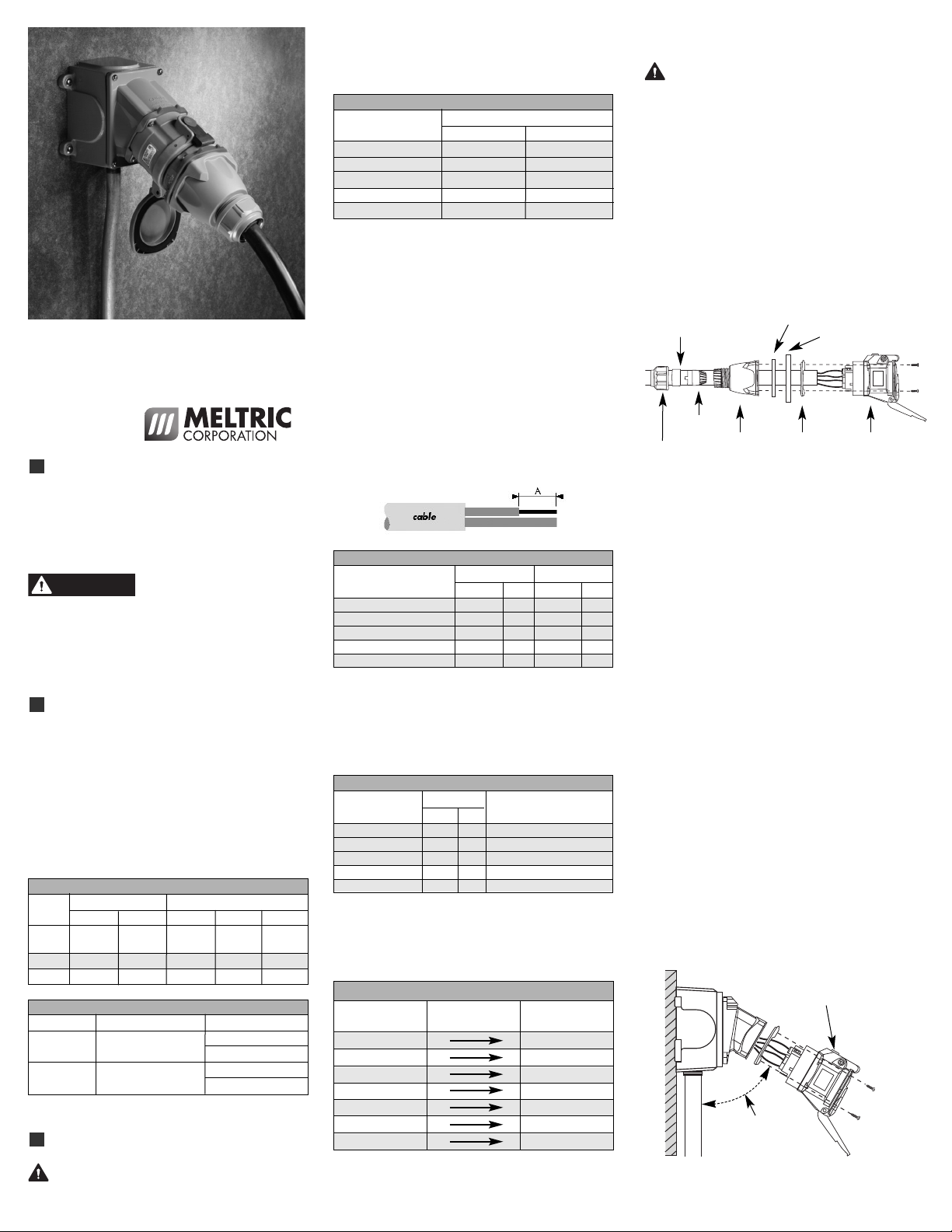
Adjust the bushing diameter to fit the cable by removing
the inner sections as required. Insert the bushing
into the strain relief, then insert the assembly into the
handle and loosely install the compression nut.
Insert the cable through the handle, the thin black
(neoprene) drawplate gasket, the finger drawplate
(if applicable) and the color coded gasket. Strip the
cable sheath to provide a workable wire length, being
mindful that the sheath must extend into the handle
to achieve a secure cord grip. Then strip the individual
wires to the lengths indicated in Table 2 and twist the
strands of each conductor together.
Back out the terminal screws on the receptacle (or
inlet) far enough (but not completely) to allow the
conductors to pass. Insert the conductors fully into
their respective terminals and tighten the terminal
screws with the appropriate tool to the torque
indicated in Table 3.
Verify that the cable sheath extends beyond the strain
relief and into the handle. Assemble the receptacle
(or inlet), the color coded gasket, followed by the
finger drawplate, and the thin black (neoprene)
drawplate gasket (if applicable) to the handle and
tighten the compression nut to secure the cable.
Assembly for Mounted Receptacles (or Inlets)
In applications where the receptacles (or inlets) are
mounted to wall boxes, panels or other equipment,
optimal operation is achieved when the devices are
installed with the latch at the top.
Insert the cable or wires through the wall box and cut
to allow adequate length. Strip the cable sheath as
Compression
Nut
Handle
Strain
Relief Color-Coded
Gasket
Receptacle
(or Inlet)
Bushing
Finger Drawplate Gasket
Finger Drawplate
Table 4 - Wire Strip Length – Dimensions A
Receptacle Plug/Inlet
Device/Contacts Inches mm Inches mm
DN7c (50A) Contact 3/4 20 3/4 20
DN7c (90A) Contact 1 25 1 25
DN7c (150A) Contact 1 3/16 30 1 3/16 30
DN9c Contacts 1/2 13 1/2 13
DN20c Contacts 1/2 13 1/2 13
Mount with the latching pawl at
the top to counteract the weight
and strain of the plug & cable.
Mount the receptacle
at a downward angle
whenever possible.
Table 3 — Wiring Terminal Capacity* (in AWG)
Contacts
Device Min Max
DN7c (50A) 10 6
DN7c (90A) 82
DN7c (150A) 6 3/0
DN9c 16 10
DN20c 16 10
*Capacity is based on THHN wire sizes.
Table 5 - Terminal Screw Tightening Tor ues
Tor ue Re uired Screwdriver
Device/Contact in-lbs N-m or Allen Wrench
DN7c (50A)Contact 13.3 1.5 5/64” hex head 2mm hex head
DN7c (90A)Contact 30.0 3.5 1/4” precision tip
DN7c (150A) Contact 80.0 9.0 4 mm hex head
DN9c Contact 4.50 0.5 5/64” hex head 2mm hex head
DN20c Contact 4.50 0.5 5/64” hex head 2mm hex head
Table 6 - DN9c & DN20c Wiring
Plug/Inlet Corresponding Receptacle
Contact Nos. mating pin Contact Nos.
F1 (Ground) S1 (Ground)
F2 S2
F3 S3
F4 S4
F5 S5
F6-19 S6-19
F20 S20
OPERATING INSTR CTIONS
INSDN I
Meltric Corporation / 4765 W. Oakwood Park Drive Franklin, WI 53132
A manufacturer of products using Marechal technology
meltric.com
DN7C/DN9C/DN20C
M LTIPIN
Table 2 — hort Circuit Withstand Ratings
Device Rating Fuse Type*
DN9c 10 kA @ 480 VAC
DN20c 10 kA @ 480 VAC
*Ratings applies with fusing up to this amperage. Ratings are based
on tests performed with Ferraz Shawmut current limiting fuses.
R 1 NTD 35 A
R 5 TD 20 A
R 1 NTD 35 A
R 5 TD 20 A
Table 1 — Maximum HPat Rated Voltage Levels
1-Phase 3-Phase
Device 120 V 240 V 208 V 240 V 480 V
HP FLA HP FLA HP FLA HP FLA HP FLA
(A) (A) (A) (A) (A)
DN9c 1/3 7.2 18 27.8 3 9.6 5 7.6
DN20c 1/6 4.4 1/2 4.9 1 4.8 1 4.2 3 4.8
WARNING
desired, then strip the individual wires to the lengths
indicated in Table 2 and twist the strands of each
conductor together. Back out the terminal screws on
the receptacle (or inlet) far enough (but not completely)
to allow the conductors to pass. Insert the conductors
fully into their respective terminals and hand tighten
the terminal screws to the torque indicated in Table 3.
Assemble the receptacle (or inlet) and the color
coded gasket to the box with the appropriate hardware.
Assemble the mating plug (or receptacle) to the cord
end as indicated in the assembly instructions above
for in-line connections, except there will be no finger
drawplate or associated black gasket.
Hole Pattern for Custom Mounting
In applications where custom mounting to a panel or
box is desired, the clearance and mounting holes
should be drilled as indicated in the following diagram
and Table 7.
NOTICE: In order to maintain the IP protection pro-
vided by DN models in custom installations, water-
tight seals should be used under the heads of
the four mounting bolts and they must be retained by
a lock washer and nut on the inside of the box or
panel. Alternatively, four blind holes may be drilled
and threaded to accommodate the mounting screws,
provided that the hole depth is sufficient to achieve
adequate gasket compression.
OPERATION
To ensure safe and reliable operation, Meltric
plugs and receptacles must be used in accor-
dance with their assigned ratings.
They can only be used in conjunction with mating
receptacles or plugs manufactured by Meltric or
another licensed producer of products bearing the
TM technology trademark.
Meltric plugs & receptacles are designed with different
keying arrangements so that only plugs and receptacles
with compatible contact configurations and electrical
ratings will mate with each other.
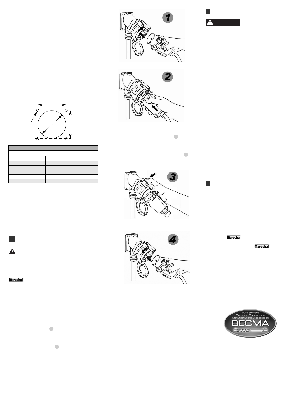
Connection
To connect a plug and receptacle, first depress the
pawl to open the lid on the receptacle and orient the
plug as shown in figure 1. Push the plug partially
into the receptacle until it hits a stop and then rotate
the plug in the counter-clockwise direction about 30°.
At this point, the circuit is still open. Push the plug
straight into the receptacle 2 until it becomes
securely latched in place. The electrical connection
is now made. For in-line connections, the use of
finger drawplates is recommended. When finger
drawplates are used, squeeze the drawplates on
both sides of the device together until the plug
latches in place.
Disconnection
To disconnect, simply depress the pawl 3. This will
open the circuit and eject the plug straight out to the
rest or off position. The plug contacts are de-energized
at this point. To remove the plug, rotate it clockwise
about 30˚ until it releases from the receptacle 4.
Close and latch the lid on the receptacle.
Achieving Rated Watertightness
Rated ingress protection applies to the device
when the plug and receptacle are mated and latched
together. It also applies to the receptacle when the
lid is latched closed.
Lockout Provisions
Some Meltric receptacles may be purchased with
optional lockout provisions. To lockout the receptacle,
close and latch the lid and then attach the locking
device through the hole provided in the pawl or
shroud. This will prevent the lid from being opened
for the insertion of a plug.
NOTICE: Attaching the receptacle locking device
with the receptacle lid open will not prevent the inser-
tion of a plug. Lockout is only accomplished when
the lid is locked closed.
MAINTENANCE
Before inspecting, repairing, or
maintaining Meltric products,
disconnect electrical power to the receptacle to
eliminate the risk of electrical shock.
Meltric products require little on-going maintenance.
However, it is a good practice to periodically perform
the following general inspections:
•Check the mounting screws for tightness.
•Verify that the weight of the cable is supported
by the strain relief mechanism and not by the
terminal connections.
• Check the IP gaskets for wear and resiliency.
Replace as required.
•Verify the electrical continuity of the ground circuit.
• Check the pin contact surfaces for cleanliness
and pitting.
Deposits of dust or similar foreign materials can be
rubbed off the contacts with a clean cloth. Sprays
should not be used, as they tend to collect dirt. If
any significant pitting of the contacts or other serious
damage is observed, the device should be replaced.
Receptacle contacts may be inspected by a qualified
technician. This should only be done with the power
turned off. The inlet contacts can be inspected by
pressing on opposite ends of the numbered face.
This will make it easier to check the contacts for
pitting or damage.
MANUFACTURER’ RE PON IBILITY
Meltric’s responsibility is strictly limited to the repair
or replacement of any product that does not conform
to the warranty specified in the purchase contract.
Meltric shall not be liable for any penalties or
consequential damages associated with the loss
of production, work, profit or any financial loss
incurred by the customer.
Meltric Corporation shall not be held liable when its
products are used in conjunction with products not
bearing the TM trademark. The use of
Meltric products in conjunction with mating devices
that are not marked with the TMtrademark
shall void all warranties on the product.
Melt ic Co po ation is an ISO 9001 ce tified company.
Its p oducts a e designed, manufactu ed and ated
in acco dance with applicable UL, CSA and IEC
standa ds. Melt ic is also a membe of BECMA, the
inte national Butt-contact Elect ical Connecto s
Manufactu e s’ Association. Like all membe s,
Melt ic additionally designs and manufactu es its
p oducts in acco dance with BECMA standa ds
established to ensu e inte matablility with simila ly
ated p oducts manufactu ed by othe membe s.
www.becma.ch
Table 7 - Custom Mounting Dimensions
‘A’ ‘B’ C
Model Inches mm Inches mm Inches mm
DN7c (50A) 3.25 83 2.59 66 .22 5.5
DN7c (90A) 4.00 102 3.20 81 .22 5.5
DN7c (150A) 4.50 114 3.86 98 .28 7.0
DN9c 2.70 69 2.18 55 .19 4.8
DN20c 4.00 102 3.20 81 .22 5.5
INSDN I
C
A
B
B
WARNING
This manual suits for next models
2
Other Meltric Industrial Equipment manuals


