Am Klopferspitz 19, 82152 Martinsried, Germany
Phone +49 89 189166 0, Fax +49 89 189166 11
http://www.menlosystems.de
08.02.2008
Page 2/2
Packing Information
When unpacking your APD210, please check that the case contains the following items:
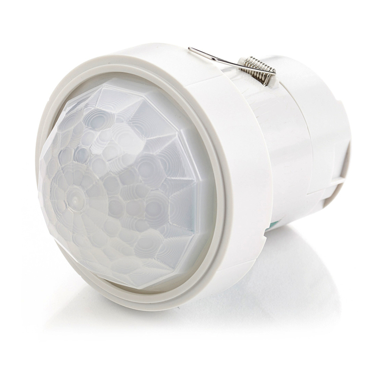
•1x APD210 Detector
•1x Power supply with country specific wall plug adapter
•1x Envelope with manual and test report
•1x Threaded mounting adapter
Setup and Operation
•After unpacking the power supply, attach the included wall plug matching your power line, to it. The power supply is now
operable. Connect the power cord from the power supply to the power jack marked Supply/15V at the rear of the detector.
•Connect Signal Out (BNC jack) to a suitable monitoring device, e.g. oscilloscope or RF spectrum analyzer, with 50Ω
impedance. Please note that a multimeter is not sufficient to check the detector for functionality.
Mount the device firmly in your setup by attaching a mounting post to the M4 threaded hole at the bottom of the device.
Please note that when the device is not mounted properly involuntary displacements during operation might occur, leading to
uncontrolled reflections from the device.
For countries using non metric threads an adapter is included.
•Switch on the power supply and the monitoring device, and apply a light source to the photo diode.
•To adjust the gain setting, please use a small pen tip to operate the hidden push buttons at the top of the device marked
“Gain adj ±”. Pressing the corresponding button once will increase/decrease the gain. Change the gain continuously by
keeping the respective button depressed. Rate of change will increase with time when the button is pressed continously. To
control the resulting gain, check the output signal with a suitable monitoring device.
Maintaining the APD210
There are no serviceable parts in the APD210. The housing may be cleaned by wiping with a soft damp cloth. Do not use any
alcohol or organic solvent to clean the mechanical parts. The window of the photo diode should only be cleaned using isopropyl
alcohol and optical grade wipes.
Troubleshooting
This compilation shall assist you in handling possible unexpected behaviour of the detector unit:
Description of problem Probable cause Solution
The gain changes during the first few
minutes after powering on the detector
For a cold device, the gain stabilization
may take a few minutes to kick in
After powering on the detector, wait a
few minutes until the stabilization works;
then adjust the gain to the desired level
Even with no light on the detector the
output signal shows periodic spikes;
A multimeter directly connected to the
detector shows an AC reading of
around 0.5V
The gain setting is too high Reduce the gain setting until the spikes
disappear
The connecting signal cable is flawed or
the impedance is not matched
Check if the cable used to connect the
output signal to the monitoring device is
flawless and fit for 50 Ohm technology;
the input impedance of the monitoring
device must be 50 Ohm.
If you suspect a problem with your detector please contact Menlo Systems and technical support will be happy to assist you. For
service requests, please make sure to provide the serial number of your device. For storage and shipping, please use the case your
detector was shipped with.
