manuals.online logo
Brands
  1. Home
  2. •
  3. Brands
  4. •
  5. Hytronik
  6. •
  7. Security Sensor
  8. •
  9. Hytronik HCD038+HIR17 Quick guide

Hytronik HCD038+HIR17 Quick guide

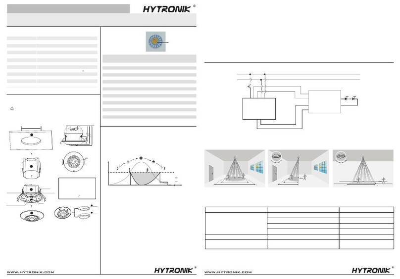
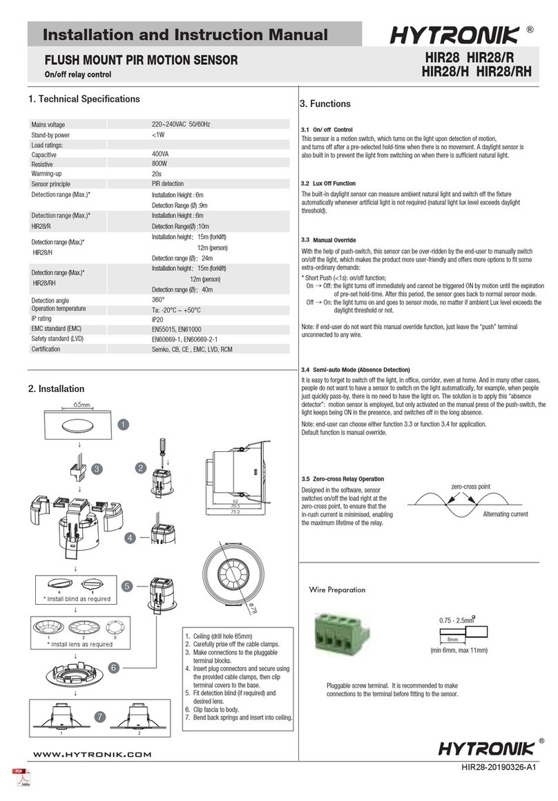
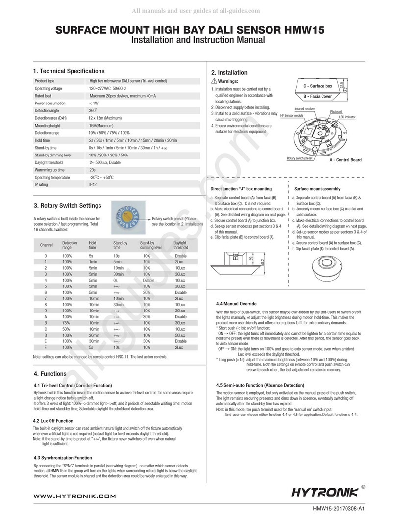
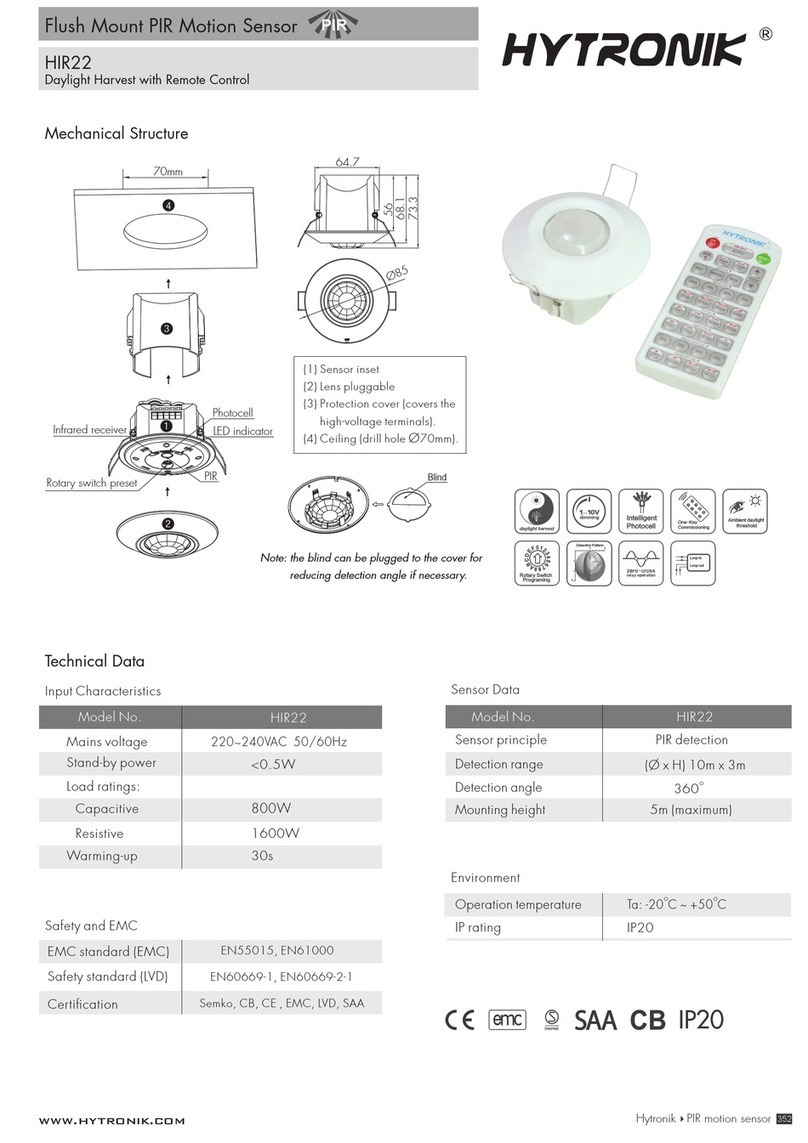
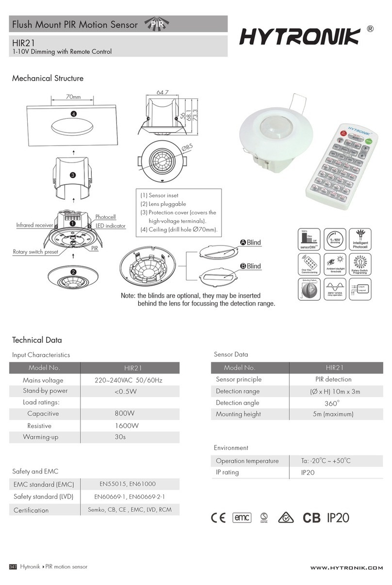
Installation and Instruction Manual
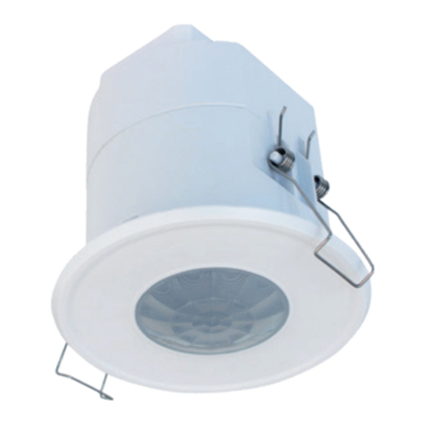
HCD038+HIR17 & HIR17/R
Detached Motion Sensor with Remote Control
HCD038+HIR17 & HIR17/R-20220817-A0
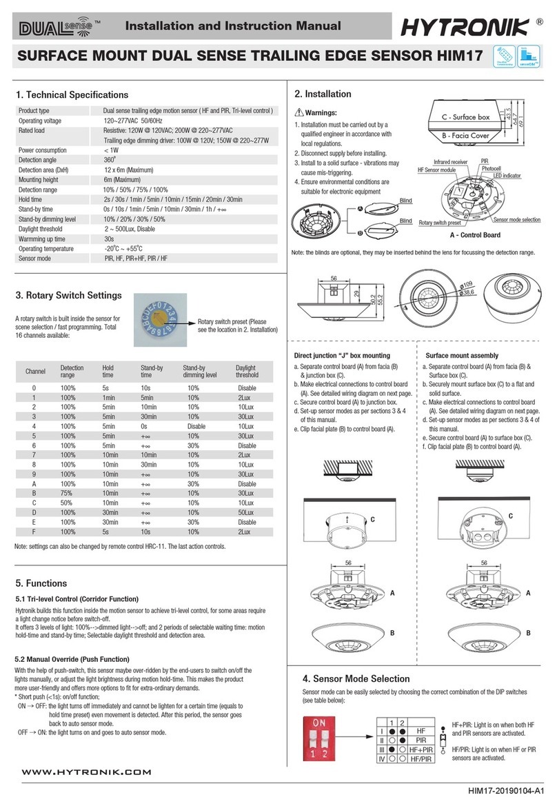
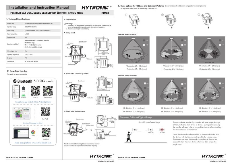
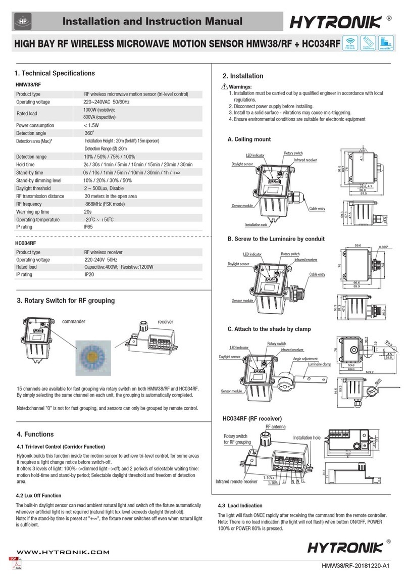
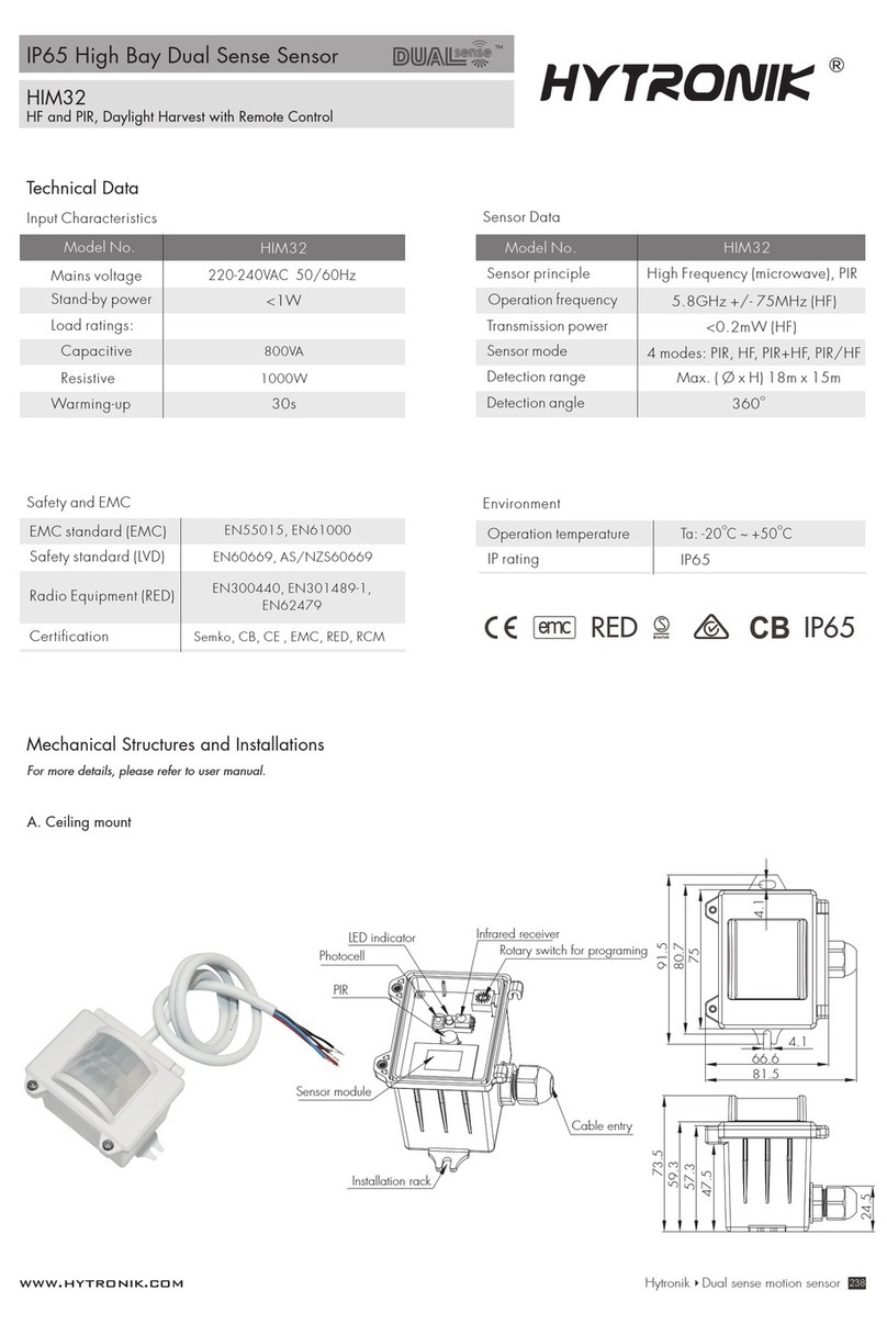
1. Technical Specifications
Tri-level Control & Daylight Harvest Sensor
2. Installation
Mechanical Structure & Dimensions
Stand-by power
220~240VAC 50/60Hz
Operating voltage
Load ratings
<0.5W
30mA (max. 15 devices)
20sWarming-up
HCD038
EMC standard (EMC)
Safety standard (LVD)
Certification
Radio Equipment (RED)
EN55015, EN61000, EN61547
Semko, CB, CE , EMC, RED, RCM,UKCA
EN60669-1/-2-1,
AS/NZS60669-1/-2-1, IEC62386
EN300440, EN301489-1/-3/-17
EN62479, EN300328
Tc: +75
°C
Operation temperature
Case temperature (Max.)
Ta: -20
°C
~ +55
°C
IP20IP rating
Detection angle
360°
5VDC
PIR detectionSensor principle
Operation voltage
Detection range *
PIR Sensor Propertie (HIR17 & HIR17/R)
HIR17
Max installation height:3m (single person)
Max detection range (Ø):12m
HIR17/R
Max installation height:8m (single person)
Max installation height:12m (forklift)
Max detection range (Ø):14m
120
30
21
RJ12 connector
N
L
DALI
Push
4.5
Ø 4.5
110.5
HCD038 (DALI output with 1 push)
PIR sensor head (Model:HIR17 & HIR17/R)
HIR17
HIR17 with HA04
Ø 15
22
52
33
9
Installation hole
17.2±0.1
44.2±0.1
R2.3±0.1
HIR17/R (IP65)
Ø 36.7
21.7
43.4
22.7
33.9
Installation hole
+ 0.78
Ø 22.23 - 0.41
HIR17 with HA05
27
Ø 15
68
Installation hole
9.4
31.8
21.7
22±0.2
60±0.2
Max R0.5
Installation hole
+ 0.78
Ø 22.23 - 0.41
1
3
21.7
22.4
31.8
Ø 32
Wire Preparation
0.5 - 1.5 mm
8mm
To make or release the wire from the terminal, use a screwdriver to push down the button.
Subject to change without notice.
3. Detection Pattern for HIR17 & HIR17/R
Wiring Diagram
DALI Driver
DALI
DALI
L
N
DALI
DALI
PUSH
N
L
L
N
DALI Driver
DALI
DALI
L
N
HIR17 HIR17/R
*The detection patterns are based upon 5km/h movement speed.
Tangential movement up to 12m
3m
Tangential movement up to 14m
12m(for forklift)
8m(for person)
4. Settings (Remote Control HRC-11, for HIR17 & HIR17/R)
Permanent ON/OFF function
Press button “ON/OFF” to select permanent ON or permanent OFF mode.
* Press button “AUTO”, “RESET” or “Ambient” to quit this mode.
The mode will change to AUTO Mode after power failure.
ON/
OFF
Press button “RESET”, all settings go back to default values (Tri-level Control mode).
Detection range: 100%; Hold-time: 5min; Stand-by period: 10min;
Stand-by dinmming level:10%; Lux disabled
Reset Settings
Press button “Shift”, the LED on the top left corner is on to indicate mode selection. All values / settings in RED are
valid for 20 seconds.
Shift Button
HCD038+HIR17 & HIR17/R-20220817-A0
1. 200 metres (total) max. for 1mm² CSA (Ta = 50℃)
2. 300 metres (total) max. for 1.5mm² CSA (Ta = 50℃)
Subject to change without notice.
AUTO mode
Press button “AUTO” to initiate automatic mode. The sensor starts working and all settings remain as before the
light is switched ON/OFF.
Note: To initiate automatic mode under semi-auto mode, please press button “RESET” first.
1. Press button “Shift”, the red LED flashes for indication.
2. Press button “SEMI-AUTO/AUTO” to initiate semi-auto mode. The fixture is manually turned on by pressing the
push-switch, and goes off automatically after stand-by time. (Absence detection mode)
SEMI-AUTO mode
Press the buttons to select light output at 80% (at initial 10,000 hours) or 100%.
Power output
Press button “Shift”, the red LED is on for indication.Then press “Tri-level” or “Harvest” to switch.
100% 75%
Tri-level Harvest
Switching between Tri-level and Daylight Harvest
Sensor off & Twilight
Press button “Shift”, the red LED is on for indication. Press button “Twilight”, the function of motion detection is
disabled. The function of photocell is still working, and the product becomes a pure dusk / dawn daylight sensor.
Press button “Sensor off”, the function of motion detection is disabled. The function of photocell is also disabled.
Sensor off Twilight
Shift
AUTO
100% 75% 50% 10%
2 Lux
100 Lux
10 Lux
300 Lux
50 Lux
500 Lux
Disable
Ambient
Memory Apply
Test
2 s
30 s
1 min 10 min
5 min 15 min 30 min
0s
10 s 1h
10% 20% 30% 50%
Dual tech & RF mode
SEMI-AUTO
Hold-time
Stand-by time
Stand-by dimming level & Auto-config.
Detection range & Sensor function
Scene prog.
Daylight threshold
RX STBY%
PIR
RX 100%
HF HF+PIR HF/ PIR
Shift Send
5 min 30 min
20 min
Power
100%
Power
80%
1 min 10 min +
Start
RESET
ON
OFF
24h 30s
12h 4h
Learn
Erase Transmit
Brightness
CCT-
CCT+
Tri-level Harvest Master
HRC-11
Scene program - 1-key commissioning
1. Press button “Start” to program.
2. Select the buttons in “Detection range”, “Daylight threshold”, “Hold-time”, “Stand-by time”, “Stand-by dimming level” to set all parameters.
3. Press button “Memory” to save all the settings programmed in the remote control.
4. Press button “Apply” to set the settings to each sensor unit(s).
For example, to set detection range 100%, daylight threshold Disable, hold-time 5min, stand-by time +∞, stand-by dimming level 30%, the steps should be: Press button “Start”,
button ”100%”, “Disable”, “Shift”, “5min”, “Shift”, “+∞”, “30%”, “Memory”. By pointing to the sensor unit(s) and pressing “Apply”, all settings are passed on the sensor(s).
Detection range
All buttons in this zone are disabled.
CCT-
CCT+
For Tri-level control, press these two buttons to adjust the light output brightness. Press button “Shift”, the red LED is on for indication. Press these two buttons to adjust the light
output colour temperature.
For Daylight Harvest, press these two buttons to adjust the light output brightness and set a new target lux level.The daylight sensor can measure ambient daylight level and ignore the
LED light, so as to calculate how much artificial light is needed to maintain the target lux level. Press button “Shift”, the red LED is on for indication. Press these two buttons to adjust
the light output colour temperature.
Brightness +/-
Hold-time
Press buttons in zone “hold-time” to set the hold-time at 2s / 30s / 1min / 5min / 10min / 15min / 20min / 30min.
Note: 1. To set hold-time at 30s / 5min / 15min / 30min, press “Shift” button first.
2. 2s is for testing purpose only, stand-by period and daylight sensor settings are disabled in this mode.
*To exit from Test mode, press button “RESET” or any button in “Hold-time”.
1. Press button “Shift”, the red LED starts to flash.
2. Press button “Ambient”, the surrounding lux level is sampled and set as the new daylight threshold.
Ambient daylight threshold
Press buttons in zone “ Daylight threshold” to set daylight sensor at 2Lux/ 10Lux / 50Lux / 100Lux / 300Lux / 500Lux / Disable.
Note: To set daylight sensor at 100Lux / 300Lux / 500Lux, press “Shift” button first.
Daylight threshold
HCD038+HIR17 & HIR17/R-20220817-A0
Subject to change without notice.
5. Additional Information / Documents
1. Regarding precautions for PIR sensor installation and operation, please kindly refer to www.hytronik.com/download ->knowledge ->PIR Sensors - Precautions for Product Installation and Operation
2. Regarding precautions for Photodiode/Photocell Usages, please kindly refer to www.hytronik.com/download ->knowledge ->Precautions for Photodiode/Photocell Usages
3. Data sheet is subject to change without notice. Please always refer to the most recent release on www.hytronik.com/products/Motion Sensors ->Built-in HF Sensor
4. Regarding Hytronik standard guarantee policy, please refer to www.hytronik.com/download ->knowledge ->Hytronik Standard Guarantee Policy
Stand-by time (corridor function)
Press buttons in zone “stand-by time” to set the stand-by period at 0s / 10s / 1min / 5min / 10min / 30min / 1h / +∞.
Note: “0s” means on/off control; “+∞” means the stand-by time is infinite and the fixture never switches off.
Dual tech & RF mode
Stand-by dimming level
Press the button in zone “stand-by dimming level” to set the stand-by dimming level at 10% / 20% / 30% / 50%.
All buttons in this zone are disabled.
Auto-configuration function
This is a function for Daylight Harvest mode, select a time period and the sensor will do light level measurement and determine / save the lowest light level (commission line) with
100% on, so as to automatically set the target lux level for daylight harvesting.
For Tri-level Control, All buttons in this zone are disabled.
HCD038+HIR17 & HIR17/R-20220817-A0
This manual suits for next models

1

Other Hytronik Security Sensor manuals

Hytronik HIR27 Quick guide

Hytronik

Hytronik HIR27 Quick guide

Hytronik Dual Sense HIM31 User manual

Hytronik

Hytronik Dual Sense HIM31 User manual

Hytronik HIR20 User manual

Hytronik

Hytronik HIR20 User manual

Hytronik HIM32 User manual

Hytronik

Hytronik HIM32 User manual

Hytronik HIR23 User manual

Hytronik

Hytronik HIR23 User manual

Hytronik HIR24 User manual

Hytronik

Hytronik HIR24 User manual

Hytronik HIM84 Quick guide

Hytronik

Hytronik HIM84 Quick guide

Hytronik HCD405/BT Quick guide

Hytronik

Hytronik HCD405/BT Quick guide

Hytronik HC403VRC-KD Quick guide

Hytronik

Hytronik HC403VRC-KD Quick guide

Hytronik HMW39/RF User manual

Hytronik

Hytronik HMW39/RF User manual

Hytronik HBHC25 Quick guide

Hytronik

Hytronik HBHC25 Quick guide

Hytronik HIR27 User manual

Hytronik

Hytronik HIR27 User manual

Hytronik HIM54 User manual

Hytronik

Hytronik HIM54 User manual

Hytronik HIM31 User manual

Hytronik

Hytronik HIM31 User manual

Hytronik HMW28/PRO User manual

Hytronik

Hytronik HMW28/PRO User manual

Hytronik HMW15 Quick guide

Hytronik

Hytronik HMW15 Quick guide

Hytronik Dual Sense HIM14 User manual

Hytronik

Hytronik Dual Sense HIM14 User manual

Hytronik HIR22 User manual

Hytronik

Hytronik HIR22 User manual

Hytronik HIR32 User manual

Hytronik

Hytronik HIR32 User manual

Hytronik HMW22 User manual

Hytronik

Hytronik HMW22 User manual

Hytronik HIR23 Quick guide

Hytronik

Hytronik HIR23 Quick guide

Hytronik HIR24 Quick guide

Hytronik

Hytronik HIR24 Quick guide

Hytronik HMW25 User manual

Hytronik

Hytronik HMW25 User manual

Hytronik HCD418-DH Quick guide

Hytronik

Hytronik HCD418-DH Quick guide

Popular Security Sensor manuals by other brands

Peak PCAN-GPS FD user manual

Peak

Peak PCAN-GPS FD user manual

LST B524IEFT-1 Specification sheet

LST

LST B524IEFT-1 Specification sheet

System Sensor SPECTRAlert CH24 Series Installation and maintenance instructions

System Sensor

System Sensor SPECTRAlert CH24 Series Installation and maintenance instructions

Enginko EGK-LW22CCM operating manual

Enginko

Enginko EGK-LW22CCM operating manual

Pentair Goyen Mecair FFD Installation and operation manual

Pentair

Pentair Goyen Mecair FFD Installation and operation manual

Aeon Labs AEO MULTISENS quick start

Aeon Labs

Aeon Labs AEO MULTISENS quick start

Powerfix Profi 298736 Operation and safety notes

Powerfix Profi

Powerfix Profi 298736 Operation and safety notes

X-Stand FREEDOM HARNESS Assembly and user's manual

X-Stand

X-Stand FREEDOM HARNESS Assembly and user's manual

Bosch AP1-P installation instructions

Bosch

Bosch AP1-P installation instructions

PCB TORKDISC 5302D-01A Installation and operating manual

PCB

PCB TORKDISC 5302D-01A Installation and operating manual

Nobile Smartmatic 9108011012 Mounting Operation Instruction

Nobile

Nobile Smartmatic 9108011012 Mounting Operation Instruction

Videoquip Phase 3 SD-2 manual

Videoquip

Videoquip Phase 3 SD-2 manual

ATD Tools ATD-3700 user manual

ATD Tools

ATD Tools ATD-3700 user manual

Optex HX-40 installation instructions

Optex

Optex HX-40 installation instructions

H2Scan HY-ALERTA 500 operating manual

H2Scan

H2Scan HY-ALERTA 500 operating manual

HESA HE400 quick start guide

HESA

HESA HE400 quick start guide

Orno OR-CR-264 quick start guide

Orno

Orno OR-CR-264 quick start guide

Salto XS4 Mini installation guide

Salto

Salto XS4 Mini installation guide

manuals.online logo
manuals.online logoBrands
  • About & Mission
  • Contact us
  • Privacy Policy
  • Terms and Conditions

Copyright 2025 Manuals.Online. All Rights Reserved.