Merand MECAFORM VE User manual
Non-binding document. The manufacturer reserves the right to modify all its products without prior notice
1TECHNICAL
SPECIFICATIONS
MA
RC
2006
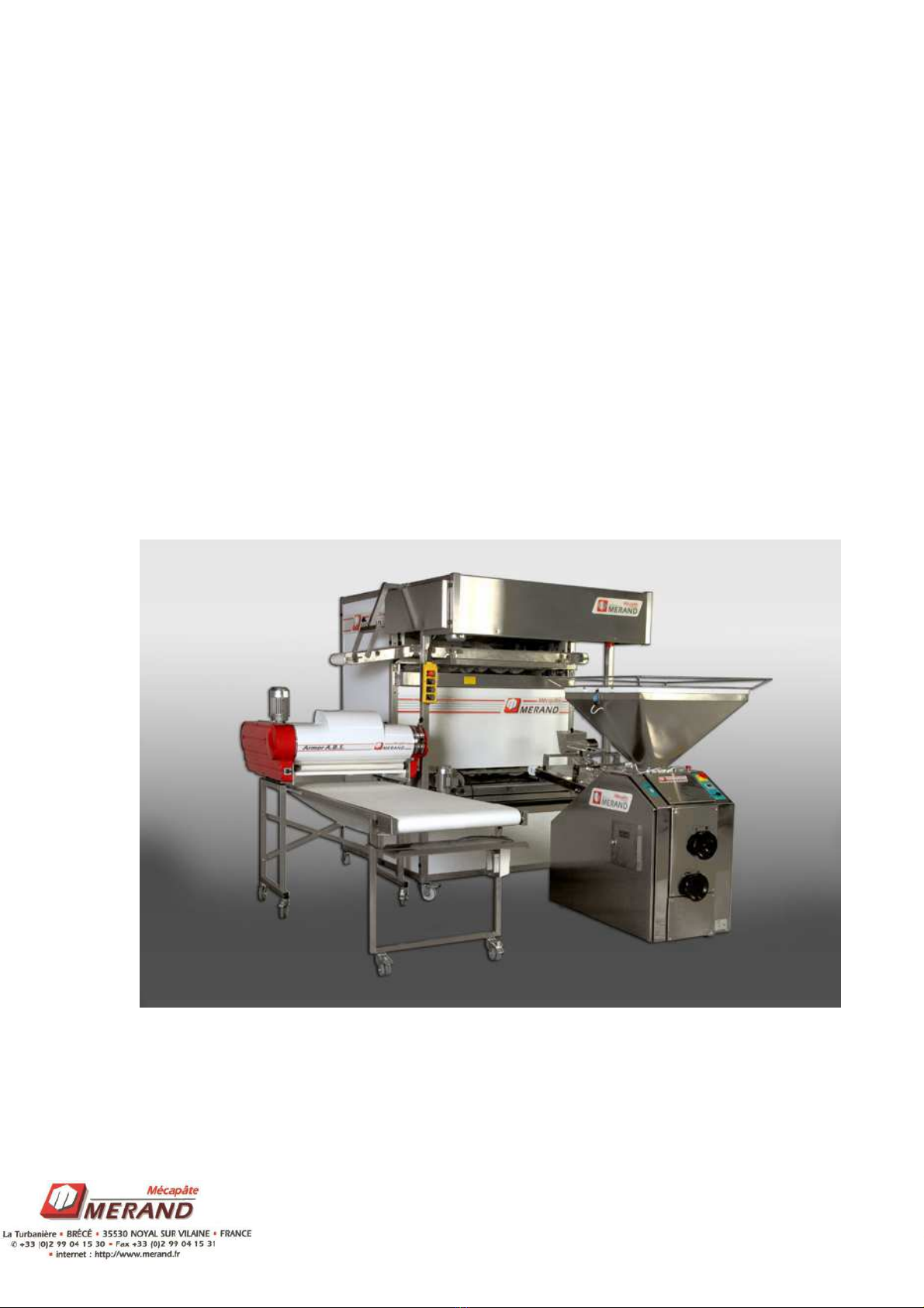
MECAFORM VE
Intermediate Proofer

Non-binding document. The manufacturer reserves the right to modify all its products without prior notice
2TECHNICAL
SPECIFICATIONS
MA
RC
2006
I. General Presentation
General safety rules
Guarantee rules
Description and function of t e equipment
- required space, electricity features, handling, production
capacity
Presentation of t e different sub-units
Description of controls
List of c eckpoints and tests to be conducted at commissioning
II. Operation Modes
Restart after sector power cut or emergency stop
Loading
Unloading
Control proofer
Cleaning
III. Malfunctioning and origins (troubles ooting)
IV. Description of operation from t e system standpoint
V. Regular maintenance
Regular maintenance c ecklist (regularity and personnel required).
VI. List of spare parts
VII. Wiring diagrams

Non-binding document. The manufacturer reserves the right to modify all its products without prior notice
3TECHNICAL
SPECIFICATIONS
MA
RC
2006
I. GENERAL PRESENTATION
General safety rules.
1- Before using MECAFORM VE, read these instructions carefully.
2 – Only bakery technicians are authorised to carry out the technical control of this
material.
3 - MERAND Mécapâte S.A shall not be liable in case of damage arising out of
failure to comply with the present instructions.
4 – Only the machines provided by MERAND Mécapâte S.A. shall fall within their
scope of responsibility, pursuant to the general selling conditions.
5 – Only professional electricians are authorized to open the switch boxes and to work
on the equipment.
6 – Never use MECAFORM VE for other purposes than those allowed.
7 – Make sure that non-authorized persons, children and animals are kept away from
all the divider components.
8 – Cut the power supply to the MECAFORM VE before any intervention.
9 – Each part must be connected to the corresponding plug.
10 – Do not look into the germicidal lamp directly (on risk of blindness).
11 - Do not clean the MECAFORM VE with steam or water jet.
12 – During all electricity works, pay attention to residual voltage.
13 – The MECAFORM VE must always be used with all the protection cases and
casing panels assembled.
Non-binding document. The manufacturer reserves the right to modify all its products without prior notice
4TECHNICAL
SPECIFICATIONS
MA
RC
2006
Guarantee rules
The MECAFORM VE AUTO is guaranteed during a 12-month period as from the
acquisition of the equipment, provided that it is operated according to the present
instructions and pursuant to the general selling conditions of MERAND Mécapâte.
The guarantee will not be valid if the proofer was not operated according to the
present instructions, or if technical operation was performed by personnel not
authorized by MERAND Mécapâte.
T E GUARANTEE S ALL NOT INCLUDE ELECTRICAL COMPONENTS.
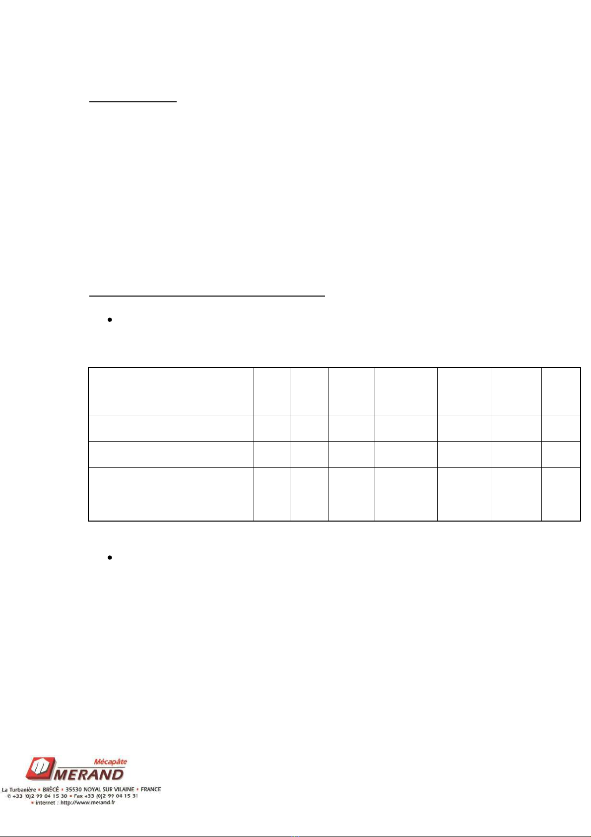
Description and function of the equipment
Required Space
Machine Name
Ext. Enhance
m.
Top width
without
delivery belt
Top depth
Height
Estimat
ed
weight
(kg)
MECAFORM VE: 56 rectanguar 7-
pocket proofers (900 g)
56 47 7 0 0 1740 1515 2240 600
MECAFORM VE: 72 rectanguar 7-
pocket proofers (900 g)
72 63 7 0 1 1740 1515 2640 800
MECAFORM VE: 78 rectanguar 7-
pocket proofers (900 g)
78 69 7 1 0 1740 2050 2240 820
MECAFORM VE: 96 rectanguar 7-
pocket proofers (900 g)
96 87 7 2 0 1740 2585 2240 1000
Electricity features
General electric power: 6.22 KW maximum.
Voltage: 380 V.
Amperage: 20.4 A max.
Frequency: 50 z.
Protection: IP 55.
Non-binding document. The manufacturer reserves the right to modify all its products without prior notice
5TECHNICAL
SPECIFICATIONS
MA
RC
2006
Handling
The MECAFORM VE intermediate proofer is equipped with four wheels, 2 with lock
to allow for movement during installation or regular maintenance. It is therefore
advisable to always move this equipment by rolling.
owever, if you need to use handling instruments to install this expansion chamber,
follow the instructions:
- Lift the equipment only from the side.
- Always use forks which are long enough to pass from one side of the proofer
to the other (to prevent the frame bottom from breaking).
- Check the position of the equipment gravity centre before lifting it
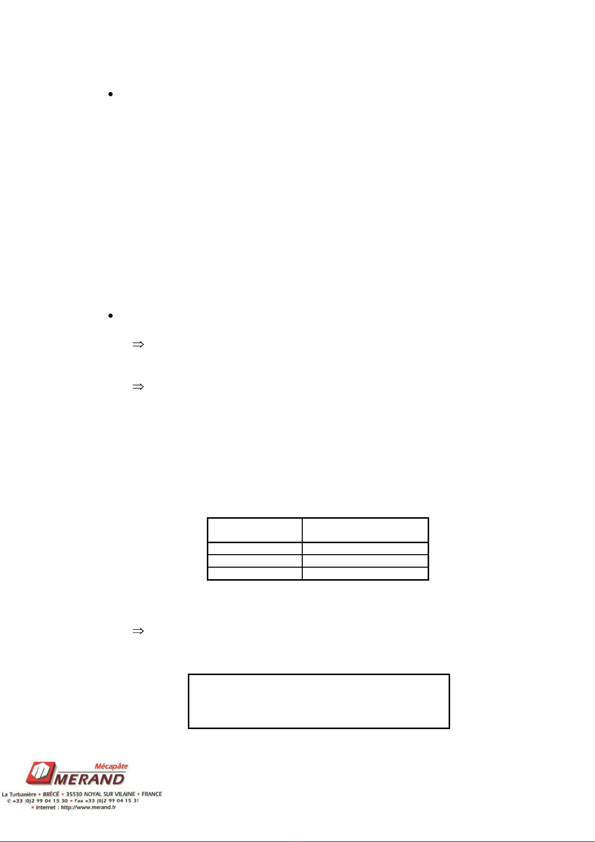
Production capacity
In loading mode, the production rhythm of the proofer is given by the
weigher.
In unloading mode, the production rhythm of the proofer is given by the
speed of the unloading belt (variable from 0 to 1800 pieces/h in the
machines equipped with the speed regulator option).
By way of information, one person alone is able to receive around 800
pieces an hour on pallets and 1200 pieces an hour on layers.
In general terms, it is important to adapt the unloading speed of the proofer
to the capacity of the moulder used.
The MECAFORM VE moulder can receive 900g rolls with 7-pocket
frames.
All this information is provided for indicative
purposes and may change subject to the dough
type and weight of rolls produced
T EGO
TENO
A MO ABS
1600
Type of moulder
1500
1200
maximum rate
Non-binding document. The manufacturer reserves the right to modify all its products without prior notice
6TECHNICAL
SPECIFICATIONS
MA
RC
2006
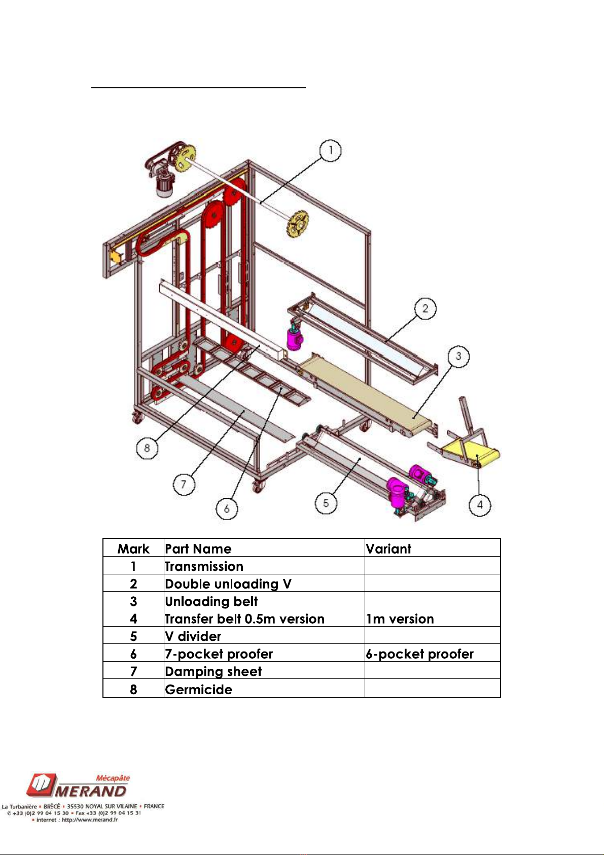
Presentation of the different sub-units
Non-binding document. The manufacturer reserves the right to modify all its products without prior notice
7TECHNICAL
SPECIFICATIONS
MA
RC
2006
0 DIV
UV
0
Special Balance
x
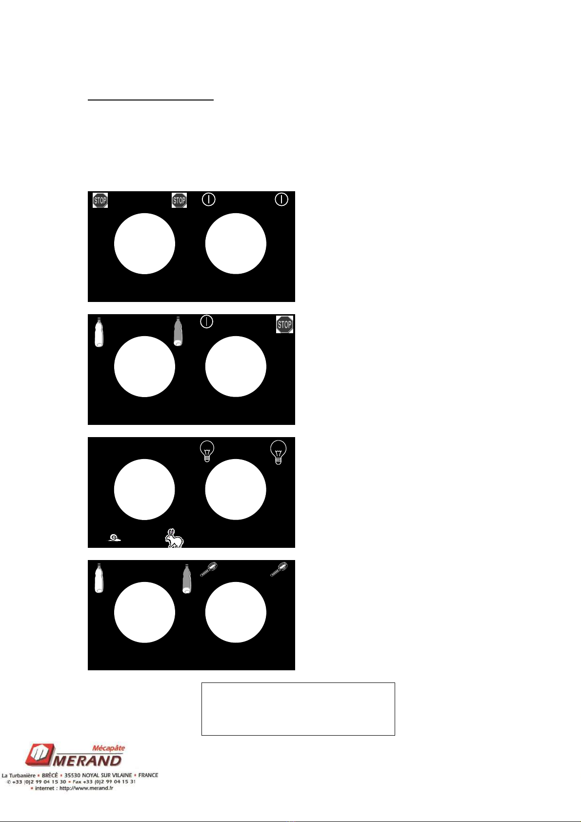
Description of controls
There follows the function of each of the buttons in the MECAFORM VE proofer
control box.
Emergency stop
General operation
Loading
0
Unloading
Weigher Start
Weigher Stop
Speed regulator adjustment
Germicidal lamp start
Germicidal lamp stop
Control proofer loading
0
Control proofer unloading
Control proofer search
The control proofer commands are
removed when equipment is fitted
with the treatment tunnel.

Non-binding document. The manufacturer reserves the right to modify all its products without prior notice
8TECHNICAL
SPECIFICATIONS
MA
RC
2006
List of checkpoints and tests to be conducted at commissioning
Check the engine rotation direction of the transfer belt. If it does not rotate in the
correct direction, then reverse two phases in the power supply plug of the
MECAFORM VE proofer.
Check that all the thermal relays, circuit breakers and disconnecting switch are
correctly engaged.
Check that all cells and sensors are working properly.

Non-binding document. The manufacturer reserves the right to modify all its products without prior notice
9TECHNICAL
SPECIFICATIONS
MA
RC
2006
OPERATING MODES
Restart after sector power cut or emergency stop
After restoring power, press the “general start” button so that the equipment performs
an initialization cycle. Once the initialization has been completed, the dough proofer
resumes the production mode selected before the stop.
Initialization cycle
The MECAFORM VE expansion chamber initialization cycle must be performed as
follows at each restart after a start or an emergency stop:
- Forward movement of the unloading belt up to the detection cell.
- Forward movement of the proofer support chain up to the proofer detection cell.
- Afterwards, the V divider and the Realignment V open, and the unloading belt
makes another forward movement up to the detection cell.
- Forward movement of the proofer support chain up to the proofer detection cell.
Once all these operations have been completed, the machine is in initial position and
waits for the launch of a new production cycle.
Loading
During the restart (after an emergency stop or a production start) push the “general
start” button.
Check that the weigher is well connected.
Put the “loading-unloading” selector on “loading” position – the cycle will start.
Note: An emergency stop during the loading cycle causes the re-initialization of the
expansion chamber.

Non-binding document. The manufacturer reserves the right to modify all its products without prior notice
10 TECHNICAL
SPECIFICATIONS
MA
RC
2006
Unloading
Put the “loading-unloading” selector on “unloading” position – the unloading cycle
will start.
Make sure that the rotating system is well engaged.
Push the “general start” button- the unloading belt will move, and a proofer will turn
while the rolls are discharged.
Note: If you put the “loading-unloading” selector on position 0 during the unloading
cycle, the equipment will stop. To restart it, put the selector back in unloading
position.
An emergency stop during the loading cycle causes the re-initialization
of the expansion chamber.
Control proofer
During the start, after the initialization of the proofer, release the turning system, then
put the “control proofer loading-unloading” switch in loading position, then push the
“control proofer search” button. The control proofer will position itself under the V
divider, and a classic loading cycle will start.
Once the loading has been completed, put the “control proofer loading-unloading”
switch back in “0”.
For unloading, engage the turning system again, and put the “control proofer loading-
unloading” switch in unloading position; then push the “control proofer search”
button. The control proofer will position itself below the unloading belt, and a classic
loading cycle will start.
Once the loading has been completed, put the “control proofer loading-unloading”
switch back in “0”.
Cleaning
When the MECAFORM VE expansion chamber is correctly initialized, push the
“germicide” button to start a 1-hour UV lamp unloading cycle. To stop this cycle,
push the “germicide” button again.
The purpose of this function is to kill mould by means of UV light.
WARNING: Do not expose unprotected parts of the body (such as eyes and skin) to
UV light.

Non-binding document. The manufacturer reserves the right to modify all its products without prior notice
11 TECHNICAL
SPECIFICATIONS
MA
RC
2006
Fan (optional)
When the selector is positioned on “fan start”, the fan located behind the equipment
will start. The purpose of this function is to extract humidity from your equipment,
allowing you to have better control of your process.
Variable flow central flour duster (optional)
By turning the potentiometer on the control unit, you may adjust the flour flow
necessary for a good flouring of proofers, before they require loading.
Treatment tunnel (optional)
By pushing the germicide start-stop button, you may combine the action of germicidal
lamps and fans. You may perform this operation throughout production, since the
frames going through the treatment tunnel are isolated from the rest of the frames.
The combined action of fans and germicidal lamps will allow you to dry pockets and
to kill mould.

Non-binding document. The manufacturer reserves the right to modify all its products without prior notice
12 TECHNICAL
SPECIFICATIONS
MA
RC
2006
III. FAULTS AND CAUSES.
Fault
Type Description Possible origins Person
intervening
Power cut Baker
Emergency stop engaged Baker
Thermal relay disconnected Baker
Power Motor does not work
Motor out of service Technician
Power
Dough proofer motor
protection disconnected
permanently
Adjustment of thermal relay Baker or
technician
Band too tight Technician
Power
Belt motor protection
(unloading or transfer)
disconnected permanently Adjustment of thermal relay Baker or
technician
The Mécaform chain does not
turn in the right direction Technician
Drive pinions misaligned or
unlocked Technician
Quick disconnect fastener of
the gutter chain is not
properly locked
Technician
Operation Abnormal noise of Mécaform
VE
Chains wrongly tightened
(drive, gutter)
Baker or
technician
Operation The proofer does not stop at
the right place
Proofer stroke end wrongly
adjusted Technician
Operation The Mécaform does not
rotate when loaded
The drive motor torque
switch must be readjusted
(by ¼ turn)
Technician
The proofer chain does not
turn in the appropriate
direction
Technician
Operation Mécaform Ve is blocked
Faulty frame Technician
or baker
Moulder misplaced Technician
or baker
Operation The dough roll does not fall
properly into the moulder Belt position is not properly
set
Technician
or baker
Operation The V’s are not well closed Adjustment of the stroke end
position Technician
Operation Belts that countersink Adjustment of the belt
tightness
Technician
or baker

Non-binding document. The manufacturer reserves the right to modify all its products without prior notice
13 TECHNICAL
SPECIFICATIONS
MA
RC
2006

Non-binding document. The manufacturer reserves the right to modify all its products without prior notice
14 TECHNICAL
SPECIFICATIONS
MA
RC
2006
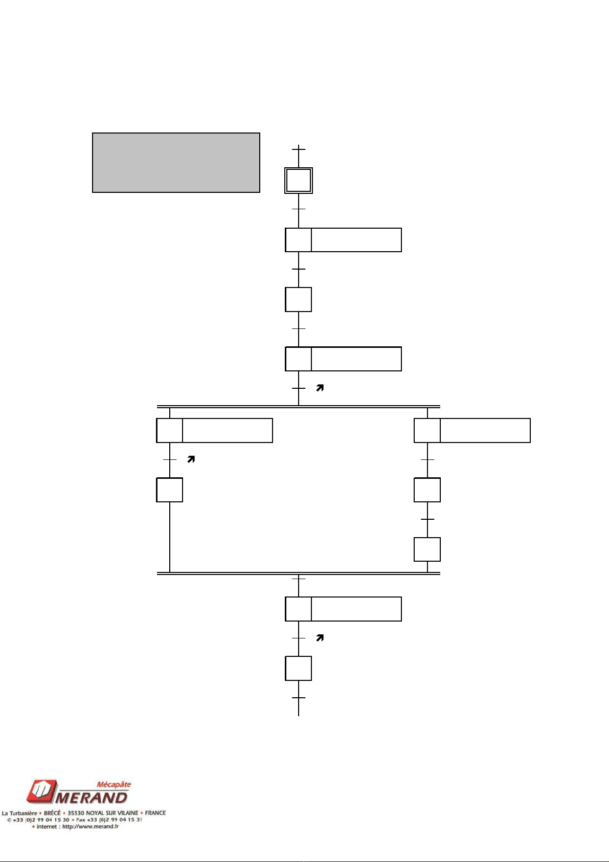
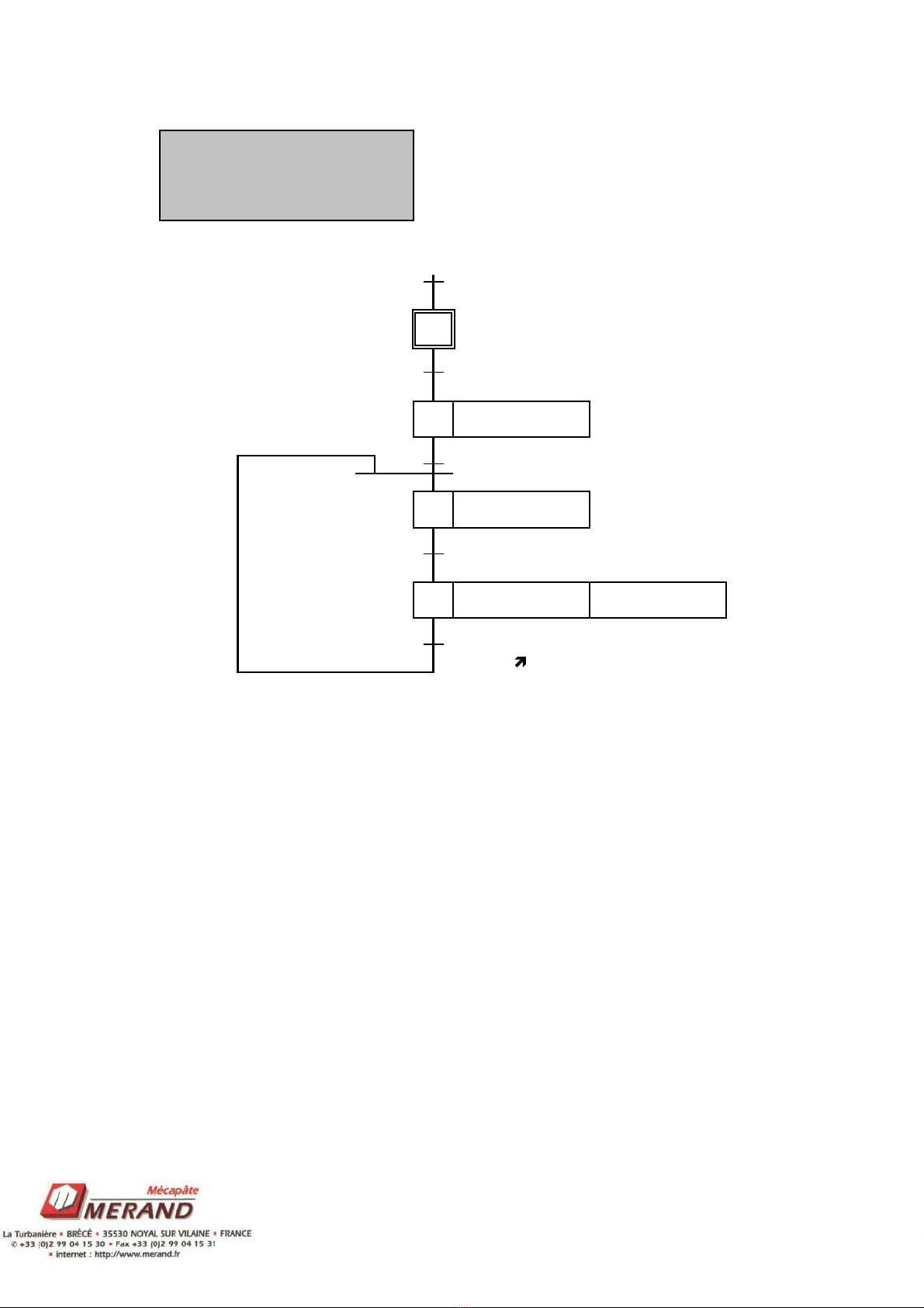
IV. DESCRIPTION OF OPERATION FROM THE SYSTEM
STANDPOINT.
G AFCET
MANAGEMENT
Faults
/Kg
%MW10
Kg.Mg
/ Init(Etp 10 grafcet init)
Init.Load./MbalT
Init.Unload./MbalT
Init.MbalT
Init.
Bp Germ
Init OK
Etp 34./Load.
/Unload.
/MbalT
Etp 74
10
11
13
14
15
16
17
12 FCT INIT. FCT LOAD. FCT UNLOAD.
FCT CTRL. PROOF.
FCT GERMICIDE
19
18 20
21
Non-binding document. The manufacturer reserves the right to modify all its products without prior notice
15 TECHNICAL
SPECIFICATIONS
MA
RC
2006
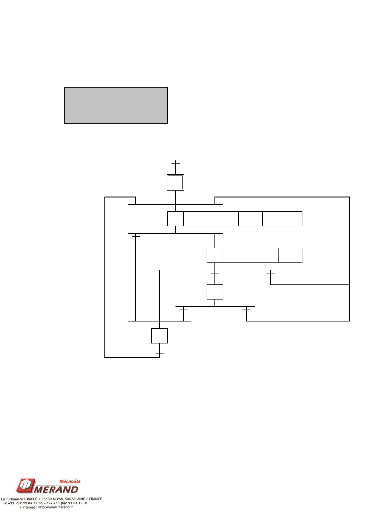
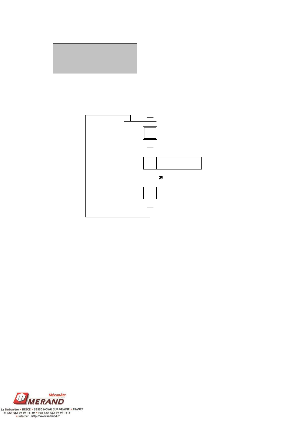
G AFCET
INITIALIZATION
/Kg
Etp 12
Cel tpvid
=1
fdc proof.
fer rev
Cel tpvid
=1
fer rev
fdc proof.
Init OK
%MW20
20
21
30
23
22
TP UNLOADING
PROOFER
26 TP UNLOAD.
25 27
24 OP. REV
28
29 PROOFER
Non-binding document. The manufacturer reserves the right to modify all its products without prior notice
16 TECHNICAL
SPECIFICATIONS
MA
RC
2006
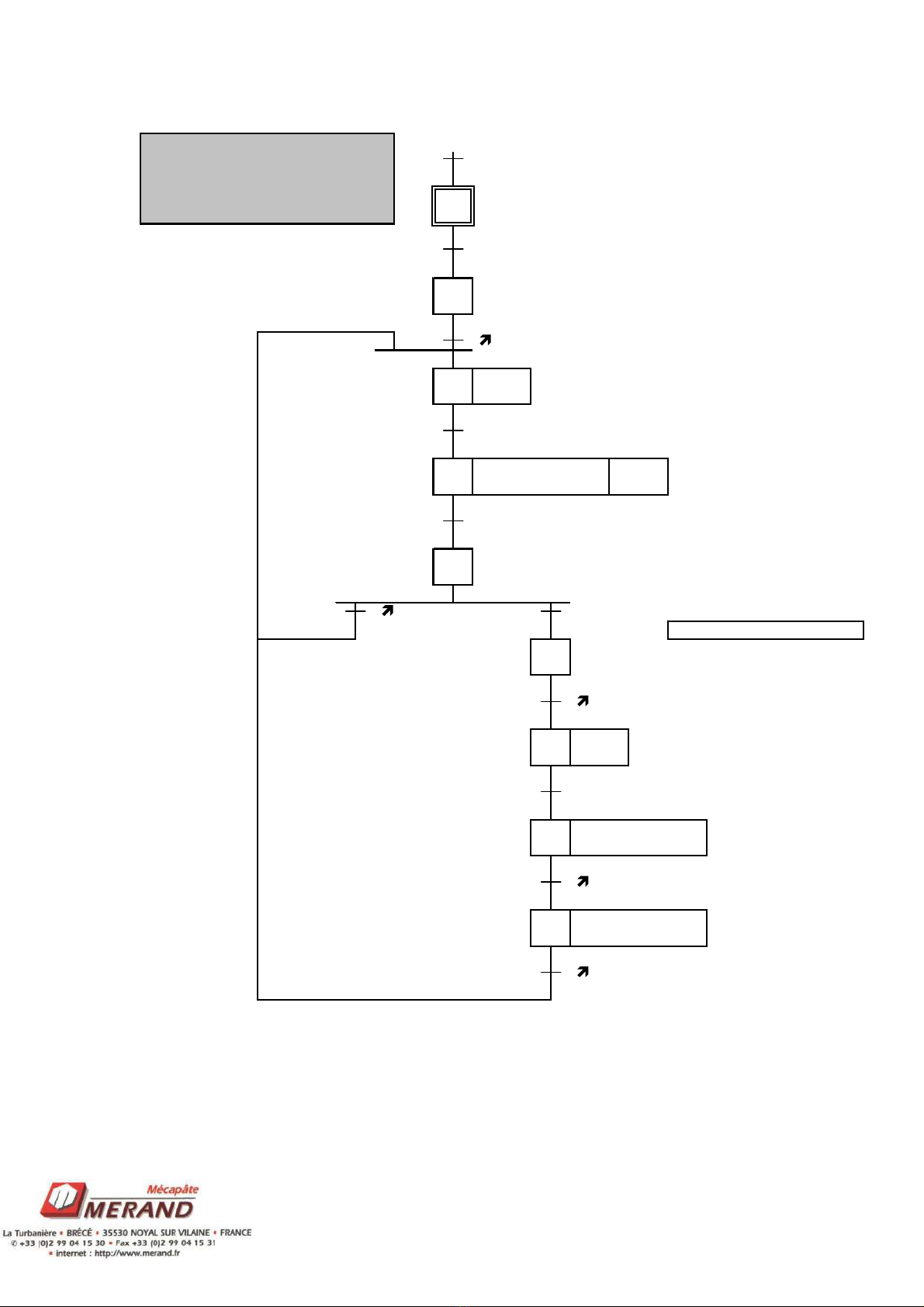
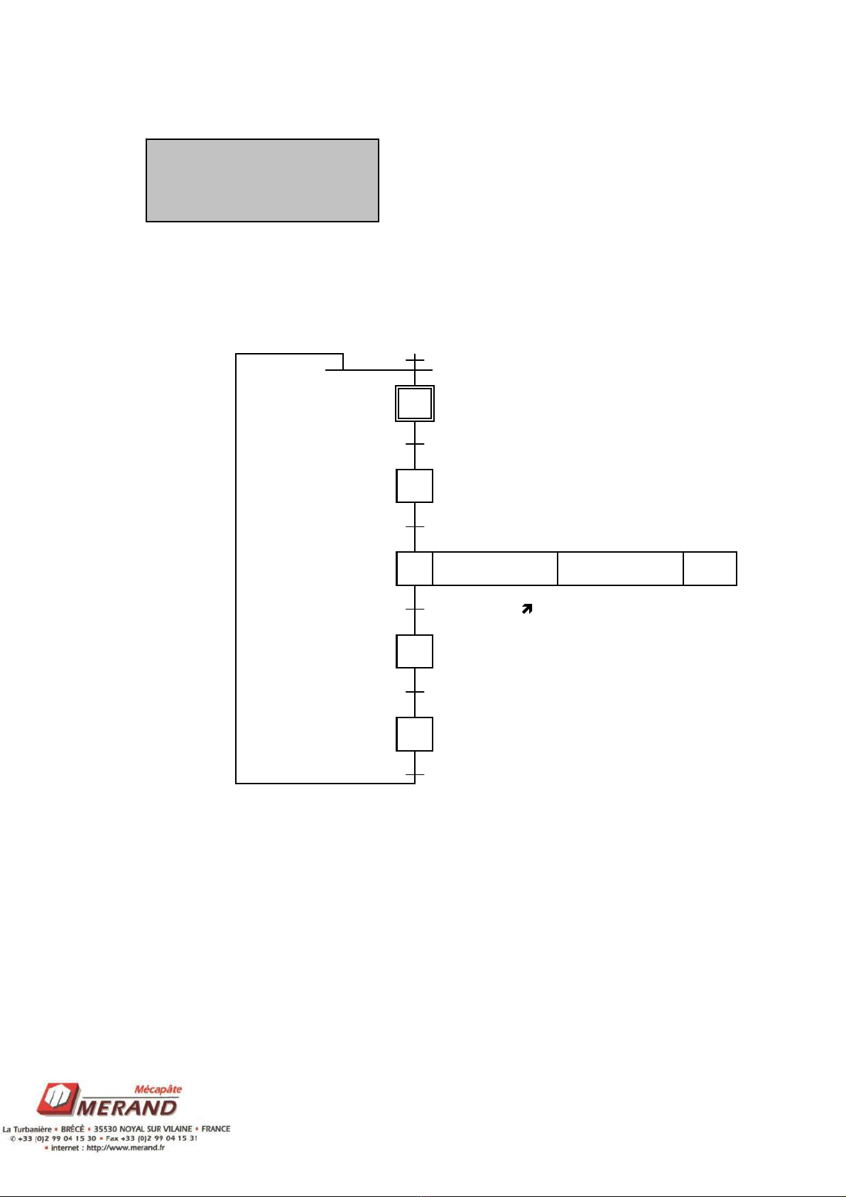
G AFCET
LOADING MGT
/Kg
Etp 14
/Loading
Apes+T1=0
/Loading
T2=0
Mpes.Loading
/Loading
Mpes.Loading
Etp 14
%MW30
30
31 G7 LOADING
32 G7 LOADING
33
34
T1
T2
WEIGHER
START
Non-binding document. The manufacturer reserves the right to modify all its products without prior notice
17 TECHNICAL
SPECIFICATIONS
MA
RC
2006
G AFCET
LOADING
/Kg
Etp 31+Etp 32
cat
T7=0
T4=0
cat.cont<X
cont>=X
X= No. of pockets to fill
cat
T7=0
fer rev
cat
OP. REV
46
T7
T4
45
48
AUTHORIZATION
PROOFER FW
42
43 FW TP REV
44
T7
47
%MW40
40
41
Non-binding document. The manufacturer reserves the right to modify all its products without prior notice
18 TECHNICAL
SPECIFICATIONS
MA
RC
2006
G AFCET
UNLOADING
/Kg
Etp 14+Etp 16+Etp72
Cel tpvid
=1
Cel tpvid.(Etp 16+Etp 72+Etp 95)
+Etp 14.
cpal.(Etp 31+Etp 32)
51
%MW50
TP UNLOADING
TP UNLOADING
52
53
50
AUTHORIZATION
FW PROOFER
TP UNLOADING
Non-binding document. The manufacturer reserves the right to modify all its products without prior notice
19 TECHNICAL
SPECIFICATIONS
MA
RC
2006
G AFCET
P OOFE FWD
/Kg
(Etp 52.(Etp16+Etp72+Etp95))
+(Etp 48.Etp 14.(Etp32+Etp 31))
fdc proofer
((Etp 52.(Etp 16+Etp 72))+(Etp 42.Etp 14)
%MW60
60
PROOFER
61
62
Non-binding document. The manufacturer reserves the right to modify all its products without prior notice
20 TECHNICAL
SPECIFICATIONS
MA
RC
2006
G AFCET
GE MICIDE
/Kg
Etp 20(Mgt Grafcet)
=1
T6=0+Etp 20.
Bp germ
=1
/Etp 20
%MW70
UNLOADING
CYCLE
71
72 GERMICIDE
70
T6
73
74
Table of contents
Other Merand Industrial Equipment manuals


