Mercedes-Benz Wallbox Home User manual

Mercedes-Benz Wallbox Home
Installation manual for
specialist electrical contractors

ii
Important addresses
Contact Daimler AG
Mercedesstraße 137
70327 Stuttgart, Germany
For technical issues, please contact your local Mercedes-Benz technical support.
This manual, in its entirety or in parts, must not be reproduced, stored electronically or otherwise transmitted electronically,
electrically, mechanically, optically, chemically, by photocopy or as an audio recording without express written permission.
Version 1.0, MB-IM_Home-2018-07-09 Article No.: 0301702_a

iii
Mercedes-Benz Wallbox Home| Contents
Contents
Important addresses ii
Important information 1
Preface 1
Notes on this manual 1
Safety notices in this manual 1
Safety notices on the device 2
General safety information 2
General product information 3
Notes regarding installation 4
Introducing the product 5
Unpacking and components
included 5
Identifying your model variant 5
Structure of the Mercedes-Benz
Wallbox Home 6
Preparations, installation and
taking into operation 9
General requirements of the
installation site 9
Requirements for the power
supply cable 9
Mechanical and electrical
installation 10
Taking the Wallbox into operation 14
Setup and test modes 15
Error detection and solutions 18
Operational malfunctions and
solutions 18
Error codes and solutions 19
Checking the internal RCCB 21
Taking the product out of and
back into operation 22
Returning your Wallbox 22
Appendix 23
Technical specifications 23
Scale drawings and dimensions 24
Wiring sequence Type 2 25
Guidelines & Norms 25
CE certification and compliance
declaration 26
Glossary & Definitions 26
Trademarks 26
Intellectual Property & Copyright 27
Disposal advice 27
Mains Connection Schemes 28

iv

1
Mercedes-Benz Wallbox Home| Important information
Important information
Preface
This manual describes the mechanical and electrical installation of the Mercedes-Benz Wallbox Home. The working steps
described in this manual must only be carried out by qualified specialist personnel (mechanical installation) and qualified spe-
cialist electrical contractors (electrical installation), who, on the basis of their specialist training, knowledge and experience as
well as their knowledge of the relevant regulations, can assess and carry out the working steps described in this installation
manual and recognize potential hazards.
The Mercedes-Benz Wallbox Home model variants can be clearly identified by the product label: These labels state the Mer-
cedes-Benz product identification number (exterior underside) as well as the ABL model number (inside of interior electronic
components cover), but are identical with regards to technical specifications. Always make sure before installation that your
model variant is the one described in this installation manual!
The following Wallbox model variants are described in this manual:
Mercedes-Benz
product identification number ABL model number
A0009067408 2W22M1
A0009067508 2W72M9
Notes on this manual
This manual documents the steps and settings required for installing the Mercedes-Benz Wallbox Home, for taking it into
and out of operation, and for resolving malfunctions during operation. For quick and easy reference, certain sections of this
manual are specially formatted.
• Descriptions listing equally valid options (as is the case here) are indicated by bullet points.
• Descriptions that describe performing a function are shown in the form of numerical lists indicating the order of the indi-
vidual working steps.
Please make sure you read this manual carefully and ensure in particular that you follow all safety notices given in this manual.
All dimensions in this manual are in millimeters. Where necessary, the scale is indicated for each illustration.
Please note that all technical details, specifications and design characteristics of the product may be changed without prior
notice.
Safety notices in this manual
In particular, the warnings and safety measures in this manual that are marked as follows must be adhered to. The symbols
carry the following meanings:
DANGER!
Sections marked with this symbol draw attention to electrical voltages that represent a danger to life and limb: Actions
contrary to these safety notices may lead to severe or fatal injury. Actions marked with this symbol must not be carried
out under any circumstances.
CAUTION!
Sections marked with this symbol draw attention to further hazards that may lead to damage to the Wallbox itself or to
other electric devices. Actions marked with this symbol must be carried out with special care.

2
PLEASE NOTE!
Sections marked with this symbol draw attention to further important information and special features that are necessary
for the reliable operation of the device. Actions marked with this symbol should be carried out as required.
Safety notices on the device
Further operational and safety notices are provided on the labels on the right hand side and underside of the housing, as well
as on the electronic components cover inside the Wallbox. These symbols carry the following meanings:
WARNING!
Please ensure that you first read the operating manual included with the Mercedes-Benz Wallbox Home, especially before
you remove the housing cover of your Wallbox.
WARNING!
Please ensure that you first read the installation manual (this document) before you remove the electronic components
cover inside the Wallbox.
DANGER!
After opening the housing, dangerous voltages may be present on the inside of the Wallbox as well as on components you
are able to touch.
General safety information
Please pay attention to the following points:
• Read this manual carefully.
• Heed all warnings.
• Follow all instructions.
• The Mercedes-Benz Wallbox Home is available with a range of country-specific specifications. Please use the identification
on the product label located on the underside of the Wallbox to check whether the Wallbox is approved to be installed and
operated in your country.
• The Wallbox must be installed, connected and approved for operation according to local rules and regulations by a qualified
specialist electrical contractor.
• Die Mercedes-Benz Wallbox Home has an internal Type A residual current circuit breaker (RCCB, see also “Glossary &
Definitions” on page 26). In addition, the Wallbox variants described in this manual also feature integrated DC fault cur-
rent detection to ensure maximum safety during operation. However, country-specific and local regulations must always be
observed. These may prescribe an RCCB with a different tripping type (e.g. Type B).
• Please ensure that minimum clearances of 50 cm are kept on all sides of the Wallbox during and after installation.
• Only use accessories intended and sold for the device by Mercedes-Benz.
• Do not install this Wallbox in close vicinity to running water or water jets: The Mercedes-Benz Wallbox Home is protected
against water entering the device according to IP55.
• The Mercedes-Benz Wallbox Home must not be installed in areas subject to flooding.
• The Mercedes-Benz Wallbox Home must not be installed in explosive atmosphere areas (EX areas).
• The Mercedes-Benz Wallbox Home must not be covered with stickers or other objects or materials to ensure sufficient air
circulation at all times.
• No liquids, objects or receptacles containing liquids must be placed on the housing.

3
Mercedes-Benz Wallbox Home| Important information
• Please note that additional overvoltage protection may be required depending on the connected vehicle and/or national
regulations.
• Please note that the fixed charging cable of the Mercedes-Benz Wallbox Home must not be extended with connectors,
adapter cables or in any other way during operation.
• Please note that operating a radio transmitter in the immediate vicinity (< 20 cm) of the Wallbox may lead to malfunctions
and should therefore be avoided.
• This device is not intended to be used by persons with limited physical, sensory or mental abilities (including children) and/
or who lack knowledge, unless they are supervised by someone responsible for their safety or have received instructions
from such a person on how to use the device.
• Children must be supervised so that they do not play with the device.
• Please note that the Mercedes-Benz Wallbox Home may be installed and operated at elevations of max. 2,000 meters
AMSL (above mean sea level).
General product information
This Mercedes-Benz Wallbox Home represents the current state of technology and complies with all current technical safety
requirements, guidelines and standards. The safety notices in this manual serve to ensure the proper and safe installation as
well as subsequent operation of the device. Disregard of or actions contrary to the safety information and instructions con-
tained in this manual may lead to electric shock, fire, severe or fatal injury.
The Mercedes-Benz Wallbox Home must be installed by a qualified specialist electrical contractor, connected according to
local regulations and provisions, and subsequently checked and approved for operation.
Malfunctions affecting the safety of persons, connected vehicles or the device itself must be repaired by an authorized spe-
cialist electrical contractor only.
Should a malfunction occur with your Wallbox, please first read the sections regarding “Error detection and solutions” on page
18. Should the fault or malfunction recur and still not be able to be resolved, please contact your local Mercedes-Benz
technical support.
Have the Wallbox taken out of operation and replaced by a qualified specialist electrical contractor or contact your local
Mercedes-Benz technical support if:
• the housing has been damaged mechanically,
• the housing cover has been removed or can no longer be fixed to the housing,
• it becomes obvious that sufficient protection against water and/or foreign objects entering the device is no longer pos-
sible,
• there is functional or visible damage to the fixed charging cable,
• or the Wallbox does not function properly or has been otherwise damaged.
DANGER!
Should you detect damage to the housing or charging cable, you must immediately discontinue installation or take the
already installed Wallbox out of operation via the upstream miniature circuit breaker (in the following called MCB, see also
“Glossary & Definitions” on page 26) in your domestic power supply and the internal RCCB: No further use of the Wall-
box is permitted in this case! Replace the Wallbox or contact your local Mercedes-Benz technical support!

4
Notes regarding installation
Please observe the following instructions for the installation of your Mercedes-Benz Wallbox Home:
• The device must always be connected to the protective earth conductor of your electricity supply. The protective earth con-
nection will be made and checked by the installing contractor. After installation, only qualified specialist electrical contrac-
tors may make changes.
• At all times comply with local safety regulations for the country in which you operate the Wallbox.
• For proper operation, the power supply for the Mercedes-Benz Wallbox Home must be protected in the domestic power
supply with an MCB (rated current depending on power supply and Wallbox settings, but no more than 32 A) that is not
followed by any other downstream electrical devices. Please always observe the applicable national requirements regarding
the selection of the MCB.
• To disconnect the Wallbox completely from the electricity grid, the power supply must be interrupted using the upstream
MCB and the internal RCCB.
• Ensure that the rated voltage and rated current of the device comply with the parameters of your local electricity grid and
that the rated output is not exceeded during the charging procedure.
• The Wallbox should not be installed in areas of high pedestrian traffic. Installation along thoroughfares and marked escape
routes should be especially avoided.
• Never install the Wallbox in a confined space. In particular, you must ensure that the vehicle can be parked at a suitable
distance from the Wallbox for charging, and connected without any strain on the charging cable. The distance between
vehicle and Wallbox should be at least 50 cm and no more than 5 m.
• You must not under any circumstances make any changes to the housing or the internal wiring of the Wallbox. Any disre-
gard of this instruction represents a safety risk, fundamentally breaches the guarantee provisions and may void the war-
ranty with immediate effect.

5
Mercedes-Benz Wallbox Home| Introducing the product
Introducing the product
The Mercedes-Benz Wallbox Home is entirely manufactured in Germany and at all times complies with the regulations and
norms for the charging of electric vehicles applicable throughout Europe according to IEC 61851-1, Mode 3 – please also
refer to the section on “Guidelines & Norms” on page 25. According to their requirements, users may select from model
variants with a range of charging outputs and fixed charging cable with Type 2 charging plug, which are designed for domestic
and semi-public applications.
We place the highest value on user safety in all our products. For this purpose, your Wallbox features an internal Type A RCCB
and integrated DC fault current detection, which, in combination with the protective measures of your domestic power supply
and of your electric vehicle, effectively protects from short circuit, electric shock and other operational hazards.
The Wallbox is especially easy to operate during everyday use: A multi-colored LED display in the lower part of the housing
cover allows you to check the current operating status at any time. Should a malfunction occur, you can identify the cause
by the specific error code displayed by the multi-colored LED without having to open the housing of the Wallbox. Aer being
taken into operation by a specialist contractor, the Mercedes-Benz Wallbox Home is ready for charging at any time, while each
charging process must be separately authorized via the integrated key switch.
Unpacking and components included
The Mercedes-Benz Wallbox Home package includes a range of accessory components needed for installation and proper
operation. Therefore, please check immediately aer unpacking whether the following components are included:
Component Quantity Description
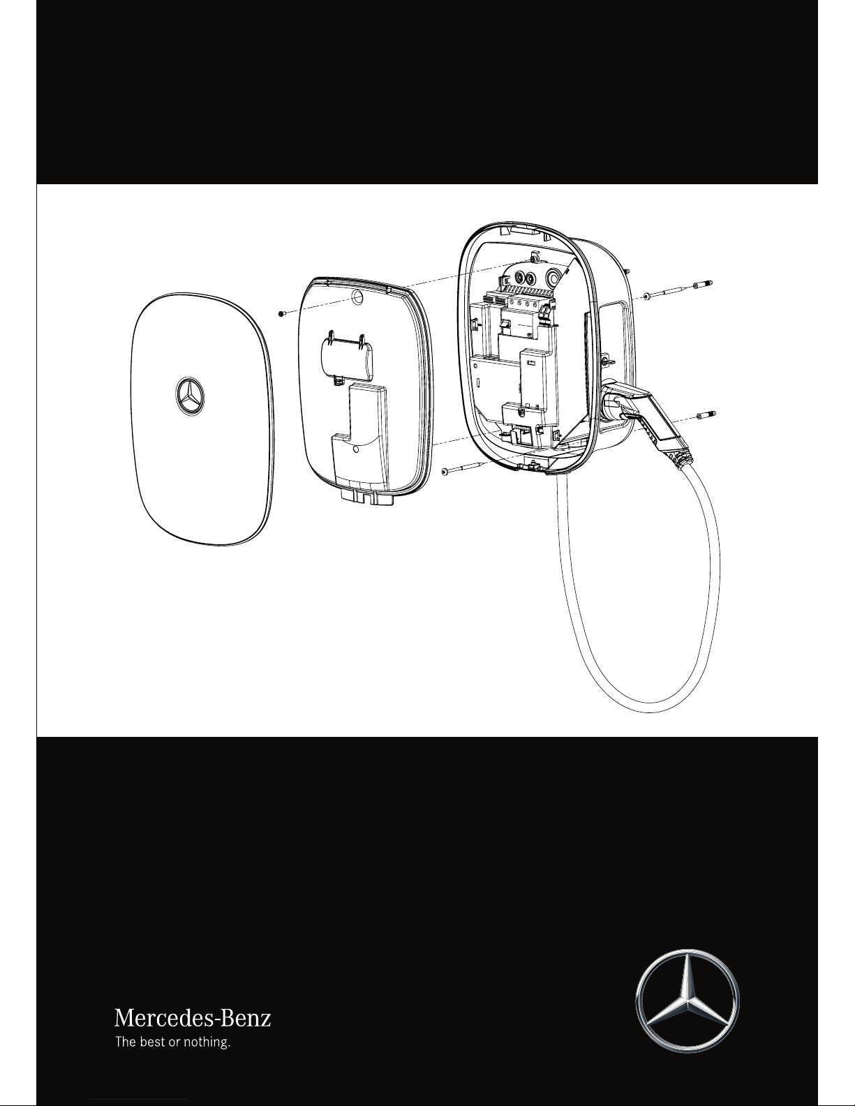
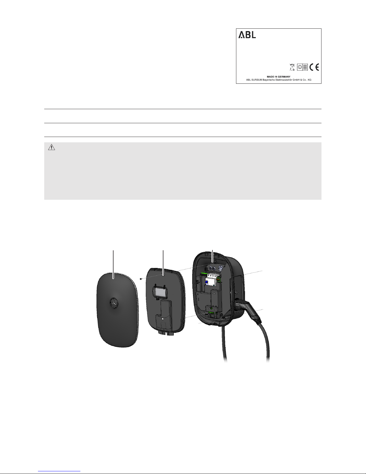
Wall box 1 Charging station consisting of housing base with integrated electronic unit, internal electronic
components cover and housing cover
Mercedes-Benz
WALLBOX Home
DE Sicherheitshinweise& Kurzanleitung HR Sigurnosnenapomene i kratke upute
EN Safetyinformation & Quick Start Guide PL Wskazówkibezpieczeństwa &
Skróconainstrukcja obsługi
FR Consignesde sécurité & Guide de prise
enmain RO Indicaţiide siguranţă & Scurt
îndrumar
IT Avvertenzedi sicurezza & brevi
istruzioni RU Указанияпо технике безопасности &
краткоеруководство
NL Veiligheidsinstructies& verkorte hand-
leiding SK Bezpečnostnépokyny & Stručný návod
PT Indicaçõesde segurança e Guia Rápido SI Varnostninapotki in kratka navodila
ES Indicacionesde seguridad & guía rápida CS Bezpečnostnípokyny & zkrácený návod
DK Sikkerhedsanvisninger& Kort
vejledning TR Güvenlikbilgileri ve hızlı başlangıç
kılavuzu
FI Turvallisuusohjeet& pikaopas HU Biztonságitudnivalókés rövid
útmutató
NO Sikkerhetsanvisningerog
hurtigreferanse AR نﺎﻣﻷا تﺎﻣﻮﻠﻌﻣ
ودليلالبدء السريع
SE Säkerhetsanvisningaroch snabbguide ZH 安全信息与
快速入门指南
ET Ohutusjuhisedja lühijuhend JP 安全情報および
クイックスタートガイド
LV Drošībasnorādījumi un ātro uzziņu
rokasgrāmata KR 안전 정보 및
빠른 시작 설명서
LT Saugosnurodymai ir trumpas naudojimo
vadovas TH
BG Указанияза безопасност и
краткоръководство TW 安全資訊及
快速入門指南
GR Οδηγίεςασφαλείας & Συνοπτικό
εγχειρίδιο
Artikelnummer:0301481_c
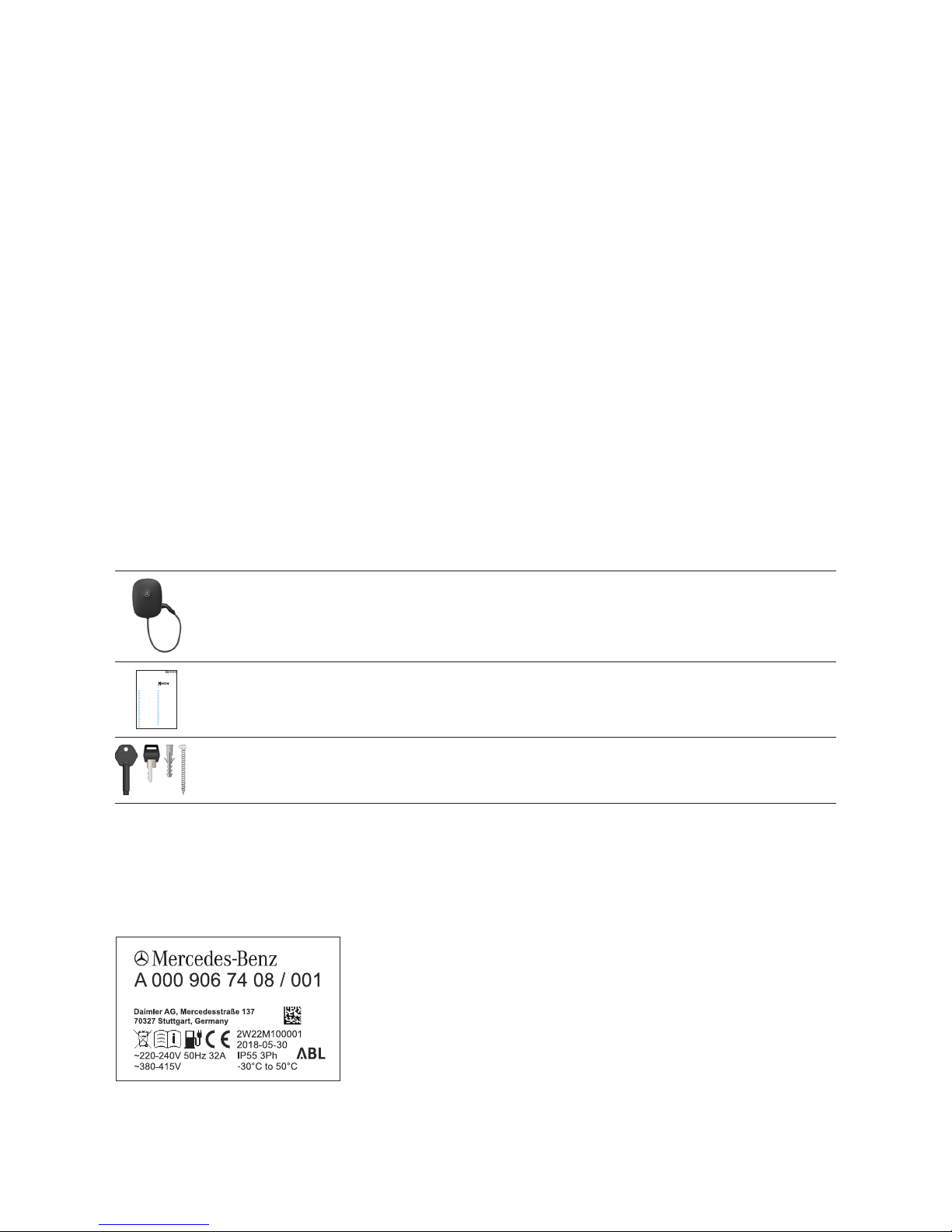
Quick start guide 1 Quick start guide including safety notices in printed form
Installation kit 1 Set of fixings for wall mounting, consisting of 2 x 4 chipboard screws as well as matching wall
plugs, keys for key switch (2 pcs.), keys for locking the housing cover (2 pcs.), drilling template
Should one or more of the components listed above be missing aer unpacking, please contact the point of sale where you
purchased the Wallbox.
Identifying your model variant
The Mercedes-Benz Wallbox Home is available in a range of model variants that are
mechanically and electrically tailored to different application profiles.
The product label with the specific Mercedes-Benz product identification number for
the Wallbox is located on the underside of the Wallbox. For identification, the model
code (A 000 906 XX XX) as well as the power supply ratings (voltage, frequency,
current) indicated below it are especially relevant.

6
When you open the housing cover for installation, you will find an additional product
information label on the inside of the RCCB access flap, which will also show the
ABL model number. Using the Mercedes-Benz product identification number or the
ABL model number, please always ensure before installation that your Wallbox model
variant is the one whose installation is described in this document. You can find a
list of the Wallbox model variants described in this manual and the correlations
between Mercedes-Benz product identification numbers and ABL model numbers in
the table below.
Mercedes-Benz product
identification number ABL model number Grid connection Model variant
A0009067408 2W22M1 230 / 400 V 50 Hz
1 or 3 x 32 A
Fixed charging cable according to IEC 62196-2 Type 2, ca. 6 m;
charging output 22 kW
A0009067508 2W72M9 230 V 50 Hz
1 x 32 A
Fixed charging cable according to IEC 62196-2 Type 2, ca. 6 m;
charging output 7.2 kW
CAUTION!
The information and technical specifications contained in this manual relate exclusively to the model variants listed in this
manual and must not be transferred to other Wallbox models: These variants include specific instruction manuals where
necessary.
Should your Wallbox model variant not be described in this manual, please contact your local Mercedes-Benz technical
support: Do not under any circumstances install the Wallbox in this case, as this could lead to damage to the Wallbox, and
to potentially fatal injury.
Structure of the Mercedes-Benz Wallbox Home
The Mercedes-Benz Wallbox Home consists of the following:
1Housing cover
Detachable outer plastic cover to be fixed to the housing base using hanging lip (upper edge) and locked using lockable screw
(lower edge)
2Electronic components cover
Internal cover for electronic module with integrated flap for manual access to the RCCB (residual current circuit breaker).
3Housing base
Base with integrated electronic module, fixed charging cable with Type 2 charging plug and charging plug storage holder
2W220100001
2W22M1
2W22M100001
2018-05-30
~220-240V 50Hz 32A
~380-415V
-30°C to 50°C, IP55
IEC 61851-1
IEC 61439-7 ACSEV
1 2 3

7
Mercedes-Benz Wallbox Home| Introducing the product
Housing cover (detail)
4Plastic lip and guides
The plastic lip is for hanging the housing cover onto the housing base. The two guide pins ensure the correct vertical position-
ing of the housing cover.
5LED zone
The multi-colored LED display is located in this part of the housing cover.
6Locking slot
The locking slot is for locking the housing cover to the housing base using the lockable screw.
Electronic components cover (detail)
7Opening for M4 fixing screw
This opening is used to fix the electronic components cover to the housing base with a fixing screw (M4 x 10).
8RCCB (residual current circuit breaker) access flap
This flap provides access to the internal RCCB of the Wallbox.
9Lens for multi-colored LED display
The multi-colored LED display is shown through this lens.
Front view Rear view
4
5
6
Front view
7
8
9

8
Housing base (detail)
0Housing cover slot
The plastic lip of the housing cover 4is inserted into this slot.
qGrommets for data cables
These grommets seal the openings for data cables in the terminals area of the housing base. Connecting data cables is pos-
sible e.g. in conjunction with a Mercedes-Benz Wallbox Advanced. Please see the relevant information on connections in the
installation manual for the Mercedes-Benz Wallbox Advanced, available at:
www.yourwallbox.de/downloads/Mercedes-Benz/Advanced/
wPower supply grommet
This grommet seals the opening for the power supply in the terminals area of the housing base.
eRCCB (residual current circuit breaker)
The RCCB and the adjacent PE terminals are for connecting the power supply.
rOpening for coded rotary switch
This opening provides access to the coded rotary switch for setting the maximum charge current and to activate set-up and
test modes (see page 21).
tOpening for LED display
The multi-colored LED display is shown through this opening.
yLockable screw for housing cover
This lockable screw is for locking the housing cover. Its key is also included.
uMounting slots
The housing base is fixed into position by hooking these two slots onto mounting screws.
iCable guide
This cable guide is intended for a surface-mounted power supply cable.
oOpenings for screw fixings
These openings are used to fix the housing base into position with two screws aer it has been hooked onto the mounting
slots u.
Rear view
Front view
o
w
e
u
i
t
y
r
0
q

9
Mercedes-Benz Wallbox Home| Preparations, installation and taking into operation
Preparations, installation and taking
into operation
General requirements of the installation site
Your Mercedes-Benz Wallbox Home is an electrical device and is therefore subject to particular requirements for indoor and
outdoor installation. In selecting the installation site, you must consider the following points:
• Observe all local regulations for electrical installations, e.g. regarding fire protection and accident prevention.
• The Wallbox must be installed where it is freely accessible to all authorized users.
• A parking spot must also be planned for in front of the Wallbox so that the vehicle's charging
connector can at all times be reached with the fixed charging cable of the Wallbox.
• The recommended installation height is 120 to 140 cm from the floor to the lower edge of
the housing. This recommendation may be adjusted upwards or downwards depending on
local conditions. Sufficient air circulation must be ensured at the installation site so that the
Wallbox is cooled during operation: Always observe the allowed operating temperatures (see
“Technical specifications” on page 23).
• To ensure the safe operation of the Wallbox, minimum clearances of 50 cm must be ob-
served on all sides of the housing.
• The mounting area must have an even surface that provides sufficient stability for installing
the Wallbox.
• The required mounting area for the Mercedes-Benz Wallbox Home is at least 440 x 330mm
(H x W). The entire rear surface of the Wallbox must be in contact with the mounting sur-
face.
• In general, the Mercedes-Benz Wallbox Home is engineered for operation in high ambient
temperatures. However, it must always be ensured that the maximum operating temperature is not exceeded through exter-
nal influences such as direct sunlight or similar.
• The Wallbox meets the requirements for outdoor installation. Outdoors, it is recommended that the Wallbox is only installed
in a covered location that provides sufficient protection from the weather.
Requirements for the power supply cable
The following standards must always be taken into account for the electrical installation of the Mercedes-Benz Wallbox Home:
• All regulatory requirements for low voltage installations according to IEC 60364-1 and IEC 60364-5-52 apply.
• The A0009067408 model variant is intended for connection to and operation on rated voltages of 230V (phase-neutral,
single phase) or 400V (phase-phase, 3-phase) and 50Hz. The A0009067508 model variant is designed for connection to
and operation on a rated voltage of 230V (phase-neutral, single phase) and 50Hz.
• The installation site must offer a sufficiently dimensioned power supply cable according to HD 60364-7-722:2012: This
power supply must be reserved exclusively for the Wallbox and must not be used to supply other electrical devices.
• If necessary, a separate power supply must be installed that is intended exclusively for connecting the Wallbox and com-
plies with the general requirements for cabling and building infrastructure.
min. 50 cm
120 to
140cm

10
• Depending on the desired rated power, the installation of the Wallbox may need to be registered with and/or approved by
the local electricity grid operator before the device is taken into operation. Please consult the regulations of your local
electricity grid operator.
• Cable dimensions must be adjusted according to the desired rated power and other
aspects (such as cable length, material, cabling method etc.). The terminal blocks in the
Wallbox are designed for cable dimensions from 1.5mm2to 16mm2.
• The power supply cable may be installed above or below the wall surface. If the power
supply cable is installed above-surface, a cable guide is provided at the back of the hous-
ing to guide the cable to the terminals area of the housing base.
• The power supply for the Wallbox must always be protected by its own MCB (rated cur-
rent depending on the power supply and Wallbox settings, but no more than 32 A). Please
always observe the applicable national requirements regarding the selection of the MCB.
• If you want to take the Wallbox out of operation, switch the upstream domestic MCB and
the internal RCCB to the 0(OFF) position.
• Please always ensure that the installation requirements listed in this manual are complied with. Disregard or actions to the
contrary may lead to severe, even fatal injury by electric shock. In addition, in case of contravention of the notices given,
the proper operation of the Wallbox cannot be guaranteed.
PLEASE NOTE!
In order to achieve the maximum charging output of the Wallbox, the power supply cable must be dimensioned and
installed for 32 A. The maximum charge current (see “Setup and test modes” on page 15) must also be set to 32 A.
Factory settings are 16A for the A0009067408 and 32A for the A0009067508 model variant.
PLEASE NOTE!
In some countries, the above-mentioned requirements are different from the prerequisites for connecting to the local
power grid. In this case, the Wallbox must be connected in accordance with the respective type of mains power connec-
tion for the country of installation. You can find an overview of country-specific mains connection schemes on page 28
in this manual or on the www.yourwallbox.de website via the following link:
www.yourwallbox.de/downloads/documents/Mains_Connection_Schemes_Home_Advanced.pdf
Mechanical and electrical installation
Aer determining the mounting site for the Wallbox, you can begin with mechanical installation. For mechanical installation,
you will need the following components:
• Power drill or cordless drill (not included)
• Drill bit Ø 8 mm, appropriate for the wall material (not included)
• Drilling template for the Wallbox model variants described in this manual (included)
• Torx bit screwdrivers (TX20, TX30) (not included)
• VDE blade screwdrivers (blade thickness and length: 0.5 x 2.5mm, 80mm recommended) (not included)
• Cutter for cutting the rubber grommet to insert the supply cable (not included)
• Four 6 x 60 chipboard screws for fixing the housing base (included)
• If required: Wall plugs suitable for the mounting substrate (included: 8 x 40 nylon wall plugs)
• Spirit level if required (not included)

11
Mercedes-Benz Wallbox Home| Preparations, installation and taking into operation
DANGER!
Always observe the 5 golden rules of electrical installation:
1. Cut off all voltage sources
2. Secure all cut-off devices
3. Verify absence of voltage
4. Ground and short-circuit
5. Cover or bar access to adjacent components under voltage
Always deactivate the MCB in the domestic power supply as well as the internal RCCB before starting installation. Also
ensure that the MCB and RCCB cannot be reactivated during installation. Otherwise, there is a risk of severe or even fatal
injury through electric shock!
Proceed as follows to install the Wallbox:
1. Ensure that a sufficiently dimensioned power supply cable is available at the desired installation site. Otherwise, a power
supply cable must be installed especially.
2. Place the drilling template vertically onto the chosen mounting surface:
Use a spirit level if required. Mark the drill holes using the template.
3. Drill the mounting holes as marked (Ø 8mm). Depending on the substrate,
insert the wall plugs supplied for the mounting screws.
4. Use the TX30 screwdriver to insert two of the four 6x60 chipboard
screws included into the two upper drill holes and tighten to a distance of
4mm from the wall.
5. Place the Wallbox onto a work surface and open the lockable screw at
the lower edge of the housing base using the housing cover key provided.
Then flip the housing cover up and remove it.
Note: Protect the housing cover from scratches and other types of exter-
nal damage. Only remove the protective film from the housing cover as
your last step, immediately before completing installation.

12
6. In the upper part of the Wallbox, use the TX20 screwdriver to loosen the
M4 screw, which is used to fix the internal electronic components cover to
the housing base, and remove the electronic components cover. Keep the
screw in a safe place.
7. Make a cut into the membrane of the largest grommet w: Now insert the
supply cable through this opening.
Note: The two smaller openings sealed with grommets qare needed for
connecting with an external charge control module, e.g. via the Mercedes-
Benz Wallbox Advanced. Please see the relevant information on connec-
tions in the installation manual for the Mercedes-Benz Wallbox Advanced,
available at:
www.yourwallbox.de/downloads/Mercedes-Benz/Advanced/
8. Hang the housing base of the Wallbox at the installation site. There are
two integrated screw slots uin the upper part of the back of the housing
base to fit over the screws installed in step 4. The Mercedes-Benz Wallbox
Home is now preinstalled at the installation site.
9. Using the TX30 screwdriver, fix the housing base in place by inserting the
two remaining chipboard screws included through the two openings o
in the lower part of the housing base into the wall plugs installed in step
3 and tightening. The Mercedes-Benz Wallbox Home is now fixed to the
mounting surface.
10.If using a power supply cable with flexible conductors, ensure that the
stripped ends (12mm recommended) are fitted with wire end ferrules.
Loosen the terminal blocks of the internal RCCB, insert the power supply
conductors into their respective terminals and tighten with a torque of 2.5
to 3Nm. The wiring sequence is shown in the following diagram and table.
When tightening terminal L1, always ensure the correct position of the
factory installed conductor!
Operate the spring loaded mechanism of the PE terminal and attach the
protective PE conductor of the power supply cable here.

13
Mercedes-Benz Wallbox Home| Preparations, installation and taking into operation
The supply cable for the three-phase model variant A0009067408 must be connected as follows:
Designation Conductor color Connection coding
Phase 1 current-carrying conductor Brown 5 (L1)
Phase 2 current-carrying conductor Black 3 (L2)
Phase 3 current-carrying conductor Gray 1 (L3)
Neutral Blue N
Protective earth Green-Yellow PE
The supply cable for the single-phase model variant A0009067508 must be connected as follows:
Designation Conductor color Connection coding
Current-carrying conductor Brown 5 (L1)
Neutral Blue N
Protective earth Green-Yellow PE
DANGER!
Please note that the electronic components of your Wallbox will be damaged if you apply a voltage above 250V between
the L1 current-carrying conductor and neutral.
PLEASE NOTE!
If desired, the 3-phase model variant A0009067408 can also be connected and operated on a single phase at terminal 2
(L1): However, in this case the rated output for the Wallbox will not be achieved.
In case of an unbalanced load on the supply grid, please observe the technical requirements for installation in force lo-
cally. The Mercedes-Benz Wallbox Home is equipped with a symmetry monitoring function that can be activated using the
coded rotary switch. Please find additional information in section “Setup and test modes” on page 15.
PLEASE NOTE!
In some countries, the requirements mentioned in this manual differ from the prerequisites for connecting to the local
power grid. In this case, the Wallbox must be connected in accordance with the respective type of mains power connec-
tion for the country of installation. You can find an overview of country-specific mains connection schemes on page 28
in this manual or on the www.yourwallbox.de website via the following link:
www.yourwallbox.de/downloads/documents/Mains_Connection_Schemes_Home_Advanced.pdf
PE
L1L2L3 N

14
PLEASE NOTE!
Factory settings for the Mercedes-Benz Wallbox Home are for maximum charging currents of 16A (A0009067408 model
variant) and 32A (A0009067508 model variant). Should the charging current made available by your domestic power sup-
ply or the supply cable itself differ from these settings, the charge current settings must be adjusted accordingly inside the
Wallbox before you replace the electronic components cover and then take the Wallbox into operation. This is described in
detail in section “Setup and test modes” on page 15 and following.
Please note that the rated current indicated on the product label and configured in the firmware must under no circum-
stances be exceeded.
11.Replace the electronic components cover inside the housing base and
fix it into place with its M4 x 10 screw.
12.Hook the housing cover onto the upper edge of the housing base and
lock it using the housing cover key provided.
Note: Before you replace the housing cover, you must complete the pro-
cess of taking the Mercedes-Benz Wallbox Home into operation – please
read the following section for information on this topic.
Taking the Wallbox into operation
Aer mechanical and electrical installation, you must check the correct functioning of the Mercedes-Benz Wallbox Home for
operation and resolve any errors.
Proceed as follows to take the Mercedes-Benz Wallbox Home into operation:
1. Switch on the upstream MCB in your domestic power distribution.
2. Open the access flap 8in the internal electronic components cover and also switch on the internal RCCB (the Wallbox is
connected to the electricity grid).
When the Wallbox is connected to the electricity grid, it will initiate the start-up procedure: This includes a test of the internal
electronic components to ensure correct functioning.
The internal check routine is indicated by the LED display on the front of the Mercedes-Benz Wallbox Home as follows.
LED display Description
The LED flashes white once ...
... and then pulsates blue.
The vehicle can now be connected for charging. Initiating and terminating charging procedures is described in detail in the
quick start guide included, as well as in the comprehensive operating manual for the Mercedes-Benz Wallbox Home: You can
download the comprehensive operating manual at www.yourwallbox.de/downloads/Mercedes-Benz/Home/. Please also
refer to the operating manual of the vehicle to be charged at the Wallbox.
Aer the Mercedes-Benz Wallbox Home has been properly taken into operation, replace the housing cover and lock it into
place: This is described in step 12 above.

15
Mercedes-Benz Wallbox Home| Preparations, installation and taking into operation
PLEASE NOTE!
To finalize the process of taking the Wallbox into operation, the maximum charge current setting of the power supply must
be checked inside the Wallbox and adjusted if required using the coded rotary switch. In order to perform a final check
of the functioning of the Wallbox, the contactor of the Wallbox must be checked in test mode for correct functioning. Test
mode is described in the next section.
Setup and test modes
If no vehicle is available for taking the Wallbox into operation or for testing it, you can check the functioning of the Mercedes-
Benz Wallbox Home (contactor, CP and RCD tripping) using test mode. You can also alter the factory setting for the maximum
charging current of the Mercedes-Benz Wallbox Home in setup mode using the coded rotary switch if the charge current
made available by the domestic power supply differs from this preset value. However, the rated current indicated on the prod-
uct label must not be exceeded under any circumstances.
The electronic components module of the Mercedes-Benz Wall-
box Home provides access to the coded rotary switch, which is
factory preset to the 0position, through the opening on the le
hand side.
For test and setup mode, you can set the coded rotary switch
to one of the values indicated on the cover around the opening
using the VDE blade screwdriver (0.5 x 2.5mm). You can find an
explanation of these values in section “Settings for the coded
rotary switch” on page 17.
In order to adjust the settings using the coded rotary switch, you
must remove the housing cover and, depending on the working
step, remove or replace the electronic components cover (see
steps 5 and 6 described on page 11 in section “Mechanical
and electrical installation”).
DANGER!
After opening the electronic components cover, dangerous voltages may be present on the inside of the Wallbox as well as
on components you are able to touch. ALWAYS switch off the MCB in the domestic power supply and the internal RCCB of
the Wallbox before you continue in setup or test mode.
Always observe the 5 golden rules of electrical installation:
1. Cut off all voltage sources
2. Secure all cut-off devices
3. Verify absence of voltage
4. Ground and short-circuit
5. Cover or bar access to adjacent components under voltage
Otherwise, there is a risk of severe or even fatal injury through electric shock!
Test mode
Proceed as follows to check the functioning of the Mercedes-Benz Wallbox Home in test mode:
Working step Status of LED display
1. Switch off the power supply for the Wallbox via the upstream MCB and the internal
RCCB.
2. Remove the internal electronic components cover. Set the coded rotary switch to posi-
tion E (see table on page 17).
I
I
I
I
I
I
I
I
I
I
I
I
I
I
I
I
0
1
2
3
4
5
6
7
8
9
A
B
C
D
E
F

16
Working step Status of LED display
3. Replace the internal electronic components cover. Switch on the power supply for the
Wallbox via the upstream MCB and the internal RCCB.
4. The Wallbox will now start up in test mode. In test mode, the charge current is limited
to 6 A.
5. First, the Wallbox will perform an automated internal check.
• If an error occurs during the internal check, the LED will display error code F2:
Please also see the description on page page 19.
• If the internal check does not return an error, continue with step 6.
DANGER!
During test mode, dangerous currents are applied to the charging contacts of the Wallbox, which present a danger to life
and limb: Do not touch these contacts under any circumstances and proceed with the following actions using extreme
caution. Otherwise, there is a risk of severe or even fatal injury through electric shock!
Working step Status of LED display
6. In test mode, you can measure the voltages at the charging plug for 120seconds (see
“Wiring sequence Type 2” on page 25). Measuring the CP contact signal (frequency
and duty cycle, measurement against PE) is also possible. After 120seconds, the charg-
ing function is locked and the internal RCCB will trip.
7. To terminate test mode, switch off the power supply of the Wallbox via the upstream
MCB and switch the RCCB to the 0position.
8. Remove the internal electronic components cover. Set the coded rotary switch to either
the 0 or F position (factory settings for normal charging operations), or to another posi-
tion if you intend to operate the Wallbox on a charging current different from the factory
setting (see table on the next page).
9. Replace the internal electronic components cover. Switch the RCCB to the Iposition.
Replace and lock the housing cover.
10.Switch on the power supply for the Wallbox via the upstream MCB in the domestic power
distribution.
11.During start-up, the Wallbox will upload the setting of the coded rotary switch and then
work using the charging current set by the switch.
Setup mode
Please follow these steps to change the maximum charging current setting of your Mercedes-Benz Wallbox Home:
Working step Status of LED display
1. Switch off the power supply for the Wallbox via the upstream MCB and the internal
RCCB.
2. Remove the internal electronic components cover. Select the desired charge current by
setting the coded rotary switch to the respective position (see table on the next page).
3. Replace the internal electronic components cover. Switch the RCCB to the Iposition.
Replace and lock the housing cover.
4. Switch on the power supply for the Wallbox via the upstream MCB in the domestic power
distribution.
120 seconds
Other manuals for Wallbox Home
1
Table of contents
Other Mercedes-Benz Batteries Charger manuals