Mercury 90-895201 204 User manual

2004, Mercury Marine 90-895201 204
THIS MANUAL DESCRIBES THE SMARTCRAFT GAUGE
SYSTEMS AVAILABLE FOR YOUR BOAT
System Speedometer
and Tachometer
Operation Manual

0

1
TABLE OF CONTENTS
Basic Operation and Features 3
Auto-Detection Engine Function 5
Master Reset 6
Speedometer Display Screens 7
Tachometer Display Screens 9
Troll Control 11
Warning System 13
Warning Display Screens 14
Tachometer Calibration 18
Quick Cal Calibration 18
CAL 1 Tachometer Calibration 18
CAL 2 Tachometer Calibration 22
Speedometer Calibration 27
Quick Cal Calibration 27
CAL 1 Speedometer Calibration 27
CAL 2 Speedometer Calibration 30
NOTE:This section shows all of the display screens that are
available for System Tach and Speedometer gauges. Depend-
ing on your type of engine, not all these screens will apply.

2

3
BASIC OPERATION AND FEATURES
Tachometer Speedometer
0
1
2
34
5
6
70
10
20
30 40 50
60
70
80
Power up: Each gauge will power up when the ignition is turned on.
Gauges will stay on as long as the ignition is on.
Lights: The brightness and contrast are adjustable.
Buttons: The MODE button is used for selecting information screens.
The “+” and “–” buttons are used for setting engine speed during troll
control and setting gauge calibrations.
Troll Control: Allows the operator to set and control the idle speed
of the engine for trolling without using the throttle.
Engine Guardian System: Monitors the critical sensors on the engine
for any early indications of problems. The system will respond to a
problem by reducing engine speed in order to maintain a safe operat-
ing condition.
Warning System: The system will sound the warning horn and display
the warning message.

4
BASIC OPERATION AND FEATURES
Digital Display Screen: Displays the following engine information.
Tachometer Display Screen: Speedometer Display Screen:
DEPENDING ON ENGINE TYPE
Engine Break–in
Engine Temperature
Oil Psi
Trim and RPM
Trim and Water Pressure
Water Pressure
Battery Voltage and Engine Hours
Fuel Flow and Fuel Used
RPM
Depth
Speed / Sea temp
DEPENDING ON ENGINE TYPE
Speed
Fuel Used
COG/SOG – If there is a GPS In-
put
Distance and fuel to waypoint –
if waypoint programmed into
optional GPS
Clock – Air/Sea Temp
Inst. and Avg. Fuel Economy
Trip Odometer
Fuel Tank Levels
Oil Tank Levels
Fresh Water Levels
Waste Water Levels
Dual Engine
Trim and RPM Synchronizer –
Fuel Range
Fuel Flow
Trip Odometer
Steering Angle

5
AUTO-DETECTION ENGINE FUNCTION
On first time power up of gauge or after a “Master Reset”, gauge will
display “Auto detect”. Upon pressing the mode button, gauge will au-
tomatically determine engine type. This will preset the data monitoring
screens accordingly. The intention is to make initial setup easier.
If the gauge shows a warning of “No Starboard Engine” or “Multiple
Starboard Engines”, engine location must be properly selected (Port
and Stbd) at the engine using a Mercury engine diagnostic tool. “Mas-
ter Reset” and “Auto detect” again. (Refer to “Master Reset”).
System tach and speed come standard with an “Engine Auto–
detection Screen” this screen lets the gauge on its initial power up
automatically detect which engine type you are using and configure
the gauge to match that vessel type.

6
MASTER RESET
You can return the gauge back to factory presets through the Master
Reset command.
IMPORTANT: Performing a master reset will reset the unit back
to all factory defaults, thus eliminating any installation calibra-
tions performed during set up of product.
By pressing TROLL
–and TROLL
+simultaneously for approximately 10
seconds (Until the graphic bars “collide”), you will be able to restore
the unit back to factory presets.

7
SPEEDOMETER DISPLAY SCREENS
4
3
2
1
5
Continued Next Page
Speedometer
0
10
20
30 40
50
60
70
80
NOT ALL SCREENS MAY APPLY TO YOUR ENGINE TYPE.
When the ignition is turned on, the speedometer will show the last
screen that was displayed before the ignition was turned off.
Press MODE to change display screens. You can revert back to the
previous screen by pressing and holding MODE for 2 seconds. This
will reverse the display rotation.
NOTE:Readings can be displayed in English (U.S.) or Metric. Refer
to Calibrations.
NOTE:Descriptions are not necessarily in order on the gauge. Order
changes depending on engine type.
1. Clock - Temp –Clock, air temperature and water temperature.
The air and water temperature sensors will have to be connected
to obtain display readings.
2. Fuel Level – Displays the amount of fuel remaining.
3. Oil Level – Displays the amount of engine oil remaining, or wa-
ter/waste tank level (if attached).
4. RPM Synchronizer – Dual Engines Only – Monitors the revolu-
tions of both engines.
5. Trim Synchronizer – Dual Engines Only – Displays the trim posi-
tion of both engines. Simplifies keeping trim levels equal.

8
SPEEDOMETER DISPLAY SCREENS
7
8
9
6Speedometer
0
10
20
30 40
50
60
70
80
10 STEERING ANGLE
520PORT
6. Range – The estimated range is based on boat speed, fuel con-
sumption and fuel remaining in the tank. The numbers displayed
indicates an estimate of the distance you can travel with the re-
maining fuel. Speed input required (Paddle Wheel, Pitot Pressure
or GPS).
7. Fuel Economy – The display shows average “AVG” fuel con-
sumption as well as Instantaneous “INST” fuel economy. The
numbers displayed indicate miles per gallon “MPG” or kilometer
per liter “KM/L”.
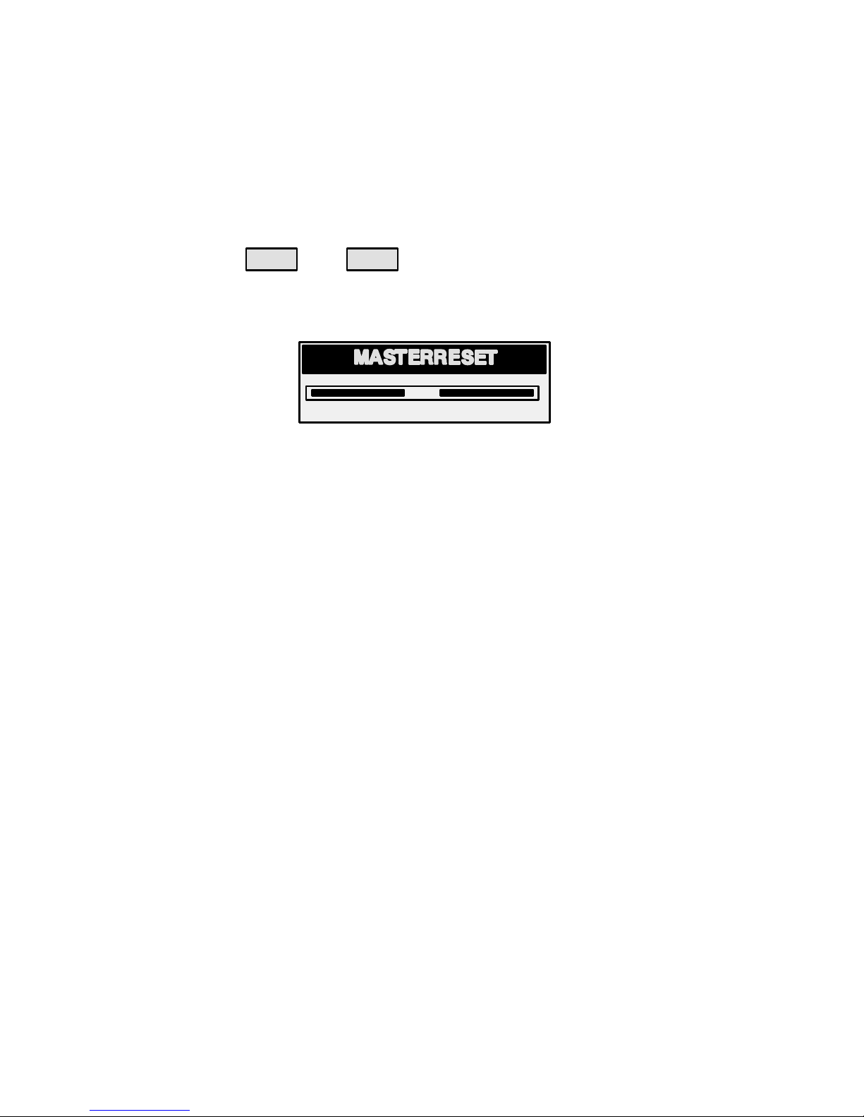
Fuel Reset – To reset, select the display screen and press
MODE and TROLL
–buttons.
8. Trip Odometer – Tells how far you’ve gone since you last reset the
gauge to zero. Trip Reset – To reset, select the display screen and
press MODE and TROLL
–buttons.
9. Digital Speedometer – Can display boat speed in miles per
hour, kilometer per hour, or nautical miles per hour. The
speedometer will use the paddle wheel for its low speed read-
ings but will switch to the speedo or GPS (if connected) for high
speed readings. (Transition point setting is described in Cal2).
10. Steering Angle – Shows the relative position of the steering
system. Available on Mercury MerCruiser models only. A steer-
ing angle sensor must be installed on the engine.

9
TACHOMETER DISPLAY SCREENS
4
3
2
1
5
°F
Tachometer
0
1
2
34
5
6
7
ENG
PSI
WATER
PSI
6
PSITMP
OKOK
BAT
NOT ALL SCREENS MAY APPLY TO YOUR ENGINE TYPE.
When the ignition is turned on, the tachometer will display the last
screen that was displayed before the ignition was turned off.
Press MODE to change display screens. You can revert back to the
previous screen by pressing and holding MODE for 2 seconds. This
will reverse the display rotation.
NOTE:Readings can be displayed in English (U.S.) or Metric. Refer
to Calibration.
1. Engine Break-in – Displays time remaining on the break-in period
of a new engine. This screen will automatically disappear after the
break-in period is complete.
2. Quick Reference Screen – Displays that the battery, engine
temperature and pressures are operating properly.
3. Temperature – Displays engine coolant temperature.
4. Power Trim Angle – Displays trim angle of the outboard or
sterndrive up to the maximum trim angle, and then displays the
trailer angle. 0 = down, 10 = maximum trim, and 25 = full trailer.
5. Power Trim Angle - Water Pressure – Displays trim angle of the
engine and cooling system water pressure.
6. Water Pressure - Displays cooling system water pressure at the
engine.

10
TACHOMETER DISPLAY SCREENS
8
7
9
Tachometer
0
1
2
34
5
6
7
HRS
VOLT
22.3
13.6
3200
FUEL USED
2.4 22.0
11
OIL
PSI
DEPTH
FEET
10
12 SPEED SEA TEMP
25 MPH 760
7. Oil Pressure – Displays engine oil pressure in units of Psi or Bar.
8. Battery Voltage – Displays voltage level (condition) of battery.
Also records the running time of engine.
9. Fuel Flow – Displays engine fuel use in gallons per hour or liters
per hour.
10. Digital Tachometer – Displays engine speed in Revolutions
Per Minute (RPM).
11. Water Depth – Displays the depth of water under the transducer
if connected. The water depth screen can be turned on or off in
CAL 1 Calibration. You can set an alarm to trigger whenever the
boat moves into water shallower than the alarm level. Refer to
CAL 2 Calibration for water depth alarm and offset settings.
NOTE:You must have a depth transducer (purchased separately)
connected to the system in order for this screen to operate.
12. Speed / Temp – Displays a split screen of water temperature
and vessel speed.
NOTE:You must have speed input installed (purchased separately).

11
TROLL CONTROL
TROLL
+
TROLL
–
TROLL
+
TROLL
–
Speedometer
Tachometer
Actual Speed Set Speed
TR
0
1
2
34
5
6
7080
Basic Operation
NOTE:Troll control may not be available on all engine models.
NOTE:Troll control min/max range may change depending on en-
gine type.
You can set the troll control by using either the tachometer or
speedometer. Tachometer will set the speed in RPM and speedom-
eter will set the speed in MPH, Kph or KN.
You can shut off troll control anytime by pushing the MODE button
when in the troll display screen or by moving the throttle.
If you have troll control set at a desired speed and then you shut off
the troll control, the system remembers the set speed and will return
to that speed when re-engaged.
The display screen will revert back to the previous screen after 10 sec-
onds of no activity. Push the TROLL
+or TROLL
–button to reactivate the
display screen.
When the troll control is engaged and you are out of the troll control
screen, a flashing signal “TR” will appear in the upper left corner of the
display to indicate troll control is still running.

12
TROLL CONTROL
0
TROLL
+
TROLL
–
TROLL
+
TROLL
–
Speedometer
Tachometer
Actual Speed Set Speed
ab
1
2
345
6
7080
To Set Troll Control
1. With the engine running, shift engine into gear. Set engine speed
at idle.
2. Push in the TROLL
+or TROLL
–button to bring up the troll control dis-
play screen.
3. Press MODE to engage (turn on) the troll control.
4. Use the TROLL
+TROLL
–buttons to set the desired speed. Use (+)
to increase speed and (–) to decrease speed.
5. If you set troll control to a higher speed than the troll rpm can bring
the boat to, the TARGET SPEED TOO FAST (a) message will ap-
pear. Reduce troll speed.
6. If you set troll control to a slower speed than the troll rpm can bring
the boat to, the TARGET SPEED TOO SLOW (b) message will ap-
pear. Increase troll speed.
To Get Out of Troll Control
There are three ways to turn off the troll control:
•Press the MODE button when in the troll display screen.
•Move the throttle to a different speed.
•Shift engine into neutral.

13
WARNING SYSTEM
ac
b
0
1
2
34
5
6
7080
2
Alarms Warnings – When a problem is detected, the name of the
offending alarm appears on the display (a).
If problem can cause immediate engine damage, the Engine Guardian
System (b) will respond to the problem by limiting engine power. Imme-
diately reduce throttle speed to idle and refer to the warning messages
on the following pages. Refer to the Engine Operation, Maintenance
and Warranty Manual for further explanation of the problem and the
correct action to take.
The alarm message will stay displayed until the mode button is
pressed. If there are multiple alarms, these will cycle on the display at
five-second intervals.
If the mode button is pressed to a different screen, the flashing alarm
signal “AL” (c) will appear in the upper right corner to indicate there
still is a problem.

14
WARNING SYSTEM
Warning Display Screens
When a problem is detected with the engine, the warning display
screens will alert the operator to the potential problem. Refer to the
Engine Operation, Maintenance and Warranty Manual for explana-
tion of the problem and the correct action to take.
WARNING DISPLAY SCREENS
PROBLEM TACHOMETER
DISPLAY
SPEEDOMETER
DISPLAY
BATTERY F
ENGINE DATA BUS F
FAULT – HORN F
FAULT – IGNITION F
FAULT – INJECTOR F
FAULT – OIL PUMP F
FAULT – SENSOR F
FAULT – WATER TEMP F
LOW FUEL F
LOW OIL F
OIL TEMP F
OIL PSI F
OVERHEAT F
OVER SPEED F
PRESSURE F
RESERVE OIL F
WATER IN FUEL F
MAP F
MAT F
TPS F

15
WARNING SYSTEM
Warning Display Screens
1
3
4
5
2
7
8
6
0
1
2
34
5
6
7
IMPORTANT: Refer to the Engine Operation, Maintenance and
Warranty Manual for further explanation of the problem and the
correct action to take.
1. OVERHEAT – The engine has overheated.
2. PRESSURE – There is insufficient water pressure in the cooling
system.
3. OVERSPEED – Engine speed exceeded the maximum allowable
RPM.
4. WATER IN FUEL – Water in the water-separating fuel filter
reached the full level.
5. FAULT-HORN – Warning horn is not functioning correctly.
6. RESERVE OIL LOW – 2 STROKE OUTBOARD ONLY – Oil level
is critically low in the engine mounted oil reservoir tank.
7. FAULT-OIL PUMP – Oil pump has stopped functioning electrically.
No lubricating oil is being supplied to the engine.
8. FAULT-INJECTOR – One or more of the fuel injectors have
stopped functioning electrically.

16
WARNING SYSTEM
Warning Display Screens
12
10
9
11
13
14
16
no starboard
engine
15
0
1
2
34
5
6
7
Multiple
Starboard Engine
9. FAULT-IGNITION – A problem has developed in the ignition sys-
tem.
10. BATTERY – The electrical system is not charging or the battery
charge is low.
11. ENGINE DATA BUS – The data communication link between the
tachometer and engine is not connected.
12. FAULT-SENSOR – One of the sensors is not functioning correctly.
13. FAULT-WATER TEMP – The sensor for measuring outside lake/
sea water temperature is not functioning correctly.
14. NO STARBOARD ENGINE – Informs you that the Instrument
does not see the starboard engine computer. Usually indicates
that no data is being transferred from the engine’s computer to the
gauge. (Check wiring, also make sure both terminator resistors are
installed in the bus). Make sure both ECMs are not configured for
port location using a DDT or Quicksilver Diagnostic Tool.
15. MULTIPLE STARBOARD ENGINE – SmartCraft Gauges are
recognizing multiple engines as starboard.
In multiple engine applications, each engine must first be assigned a
position (starboard, port, starboard2 or port2) with a Quicksilver Diag-
nostic Tool before the system will function properly.
If you have a dual engine application, you must first program the port
engine with a Quicksilver Diagnostic Tool.
16. OIL TEMPERATURE – Engine oil is overheating.

17
WARNING SYSTEM
Warning Display Screens
19
0
1
2
34
5
6
7
17
EF
18
EF22
20
21
17. OIL PRESSURE – There is insufficient oil pressure.
18. LOW FUEL LEVEL – This message serves as a warning that the
fuel level in the fuel tank is critically low. You should stop for fuel
immediately to avoid running out.
19. LOW OIL LEVEL – OUTBOARD 2 STROKE ONLY – Oil level in
the remote oil tank is low. You should stop and refill the oil tank im-
mediately to avoid running out.
20. FAULT-MAP – Engine problem occurred. Have the engine
checked by your dealer.
21. FAULT-MAT – Engine problem occurred. Have the engine
checked by your dealer.
22. FAULT-TPS – Engine problem occurred. Have the engine
checked by your dealer.

18
TACHOMETER CALIBRATION
Quick Cal Calibration
Quick Cal – This calibration is for setting lighting and contrast.
1. Press in the MODE and TROLL
+buttons for up to 2 seconds to get
to Quick Cal screen.
2. Press MODE to advance through the calibration selections.
CAL 1 Tachometer Calibration
Cal 1 –This calibration lets you turn on and off the system screens.
NOTE:Screens may vary depending upon the version of the gauge.
1. Press in the MODE and TROLL
+buttons and hold for approxi-
mately 7 seconds until you see the Cal 1 screen.
2. Press MODE to advance through the calibration selections.
[NO]
REMOTE SCREENS?
[YES][SAVE]
If yes is selected, then screen changes
made on this SC1000 tach will effect
any other SC1000 tach in the system.
NOTE: All tachs will need to have this screen
turned to “Yes” for this function to work.
[NO]
REMOTE LCD LIGHT?
[YES]
[SAVE]
If yes is selected, then lighting levels
made on this SC1000 tach will effect
any other SC1000 tach in the system.
NOTE: All tachs will need to have this screen
turned to “Yes” for this function to work.
REMOTE LCD CONTRAST?
[YES]
[NO] [SAVE]
If yes is selected, then contrast levels
made on this SC1000 tach will effect
any other SC1000 tach in the system.
NOTE: All tachs will need to have this screen
turned to “Yes” for this function to work.
[NO]
TRIM POPUP?
[YES][SAVE]
Do you want power trim display screen
to pop up momentarily when you trim
the engine?
(continued on next page)
This manual suits for next models
2
Table of contents
Other Mercury Boating Equipment manuals