Mercury SMARTCRAFT User manual

2001, Mercury Marine 90-10229021 501
THIS MANUAL DESCRIBES THE SMARTCRAFT GAUGE
SYSTEMS AVAILABLE FOR YOUR BOAT
Operation Manual

0

MONITOR 1.01-1.02
Part 1
Part 2
Part 3
Part 4
MONITOR 2.00SYSTEM TACH & SPEEDSMART TACH & SPEED
1
PRODUCT IDENTIFICATION
For boats equipped with SmartCraft gauge systems, look to
the descriptions below to identify the system in the boat.
Please read about the SmartCraft system to get the best per-
formance from them.
Monitor
Software Version 1.01 & 1.02
Part1
NOTE: Software version will
flash on screen at start up
Monitor
Software Version 2.00
Part2
NOTE: Software version will
flash on screen at start up
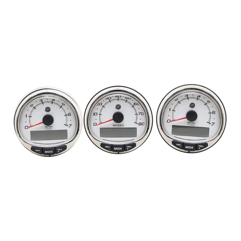
System Tachometer and Speedometer
Part 3
Note: Look for RESET
and Brightness
arrows
Smart Tachometer and Speedometer
Part4
NOTE: Look for
letters “VDO”
VDO

2

MONITOR 1.01-1.02
Part 1
Monitor with Software Version
1.01 and 1.02
Legend 1-1. . . . . . . . . . . . . . . . . . . . . . . . . . . . . . . . . . . .
Basic Operation 1-2. . . . . . . . . . . . . . . . . . . . . . . . . . . .
Standard Information Display Screens 1-3. . . . . . . . .
Shallow Water Alarm 1-6. . . . . . . . . . . . . . . . . . . . . . . .
Warning System 1-7. . . . . . . . . . . . . . . . . . . . . . . . . . . .
Warning Display Screens 1-7. . . . . . . . . . . . . . . . . . . .
CAL 1 Calibration 1-9. . . . . . . . . . . . . . . . . . . . . . . . . . .
CAL 2 Calibration 1-12. . . . . . . . . . . . . . . . . . . . . . . . . .
NOTE:This manual shows all the Monitor display
screens that are available. Depending on your type
of engine, not all these screens will apply.
Monitor with Software Version 1.01 and 1.02 is
compatible with:
2001 model year and newer Mercury Outboard mod-
els that are designed for use with SmartCraft.

MONITOR 1.01-1.02
1-0

A =
B =
C =
D =
E =
F =
I =
L =
N =
O =
P =
S =
T=
U=
= Engine
= Fuel
= Water Temperature
= Water Pressure
= Oil
= Alarm
MONITOR 1.01-1.02
1-1
MONITOR – VERSION 1.01-1.02
Legend

MONITOR 1.01-1.02
1-2
MONITOR – VERSION 1.01-1.02
Basic Operation
This monitor is an LCD multi-function display gauge. A variety of dis-
plays can be activated using the button.
Pressing the button scrolls the following displays: fuel used,
tachometer (RPM), fuel flow, power trim position, engine temp, wa-
ter pressure, battery voltage, range (if calibrated), and water depth
(if equipped with transducer).
The System Monitor will power up when the ignition is turned on.
The display includes a backlight which allows you to read it at night.
The backlight brightness is adjustable using button.
In the event of a warning alarm, the warning icon(s) will be displayed.

MONITOR 1.01-1.02
1-3
MONITOR – VERSION 1.01-1.02
Standard Information Display Screens
Initial Power Up
At power up, a momentary (1
second) screen displays the
current monitor software ver-
sion, followed by a 4 second dis-
play showing hours of engine
use.
Fuel Used
Displays approximate fuel used
since the last reset. Reset will
return display back to 0.
You can Reset anytime by
pressing and
buttons together momentarily.
Engine RPM
Tachometer – Displays engine
speed in Revolutions Per Min-
ute (RPM).
Fuel Flow
Displays current estimated indi-
vidual engine fuel consumption
in Gallons per hour (Gal/hr) or
Liters per hour (Ltr/hr).

MONITOR 1.01-1.02
1-4
MONITOR – VERSION 1.01-1.02
Standard Information Display Screens
Trim Position
Displays trim position of the pro-
pulsion unit up to the maximum
trim position, and then displays
the trailer position.
0 = down,
10 = full trim
25 = full trailer.
NOTE: This screen can be set to
pop up whenever the trim switch
is used. Refer to the CAL 1 Cal-
ibrations.
Engine Temperature
Displays the engine tempera-
ture in degrees Fahrenheit (°F)
or Celsius (°C).
Water Pressure
Displays the engine tempera-
ture in degrees Fahrenheit (°F)
or Celsius (°C).
Battery Voltage
Displays voltage level (condition)
of battery.

MONITOR 1.01-1.02
1-5
MONITOR – VERSION 1.01-1.02
Standard Information Display Screens
Range
Displays estimated range
based on current fuel consump-
tion and fuel remaining in the
tank that is connected to the
system. The number displayed
is an estimate of the distance
you can travel on the remaining
fuel at current boat speed.
NOTE: Two requirements to ac-
tivate this screen,
1. you must perform the fuel
tank calibration in CAL 2. Refer
to the CAL 2 Calibrations Sec-
tion.
2. You must have a speed input
device connected to the system
(paddle wheel or pitot pressure
transducer).
Water Depth
Displays the depth of water un-
der the transducer if connected.
NOTE: You must have a depth
transducer connected to the
system in order for this screen to
operate.

MONITOR 1.01-1.02
1-6
MONITOR – VERSION 1.01-1.02
Shallow Water Alarm
You can set an alarm to trigger whenever the boat moves into water
shallower than the alarm level.
Setting Shallow Water Alarm.
1. The water depth screen must be displayed. Be sure Depth is
turned on in CAL 2. Refer to CAL 2 Calibration Section.
2. Press both and buttons together for 3 seconds.
3. The alarm on or off menu will appear.
4. Press the button to toggle to ON.
5. Push button to save.
6. The depth number will be flashing. Press the button to set
the flashing number to desired alarm depth. 100 ft maximum
depth and 2 ft minimum depth.
7. Push button to save.

MONITOR 1.01-1.02
1-7
MONITOR – VERSION 1.01-1.02
Warning System
When a problem is detected with the engine, the warning display
screens will alert the operator to the potential problem. Refer to the
Engine Operation, Maintenance Manual for explanation of the prob-
lem and the correct action to take.
If problem can cause immediate engine damage, the Engine Guardian
System will respond to the problem by limiting engine power. Immedi-
ately reduce throttle speed to idle. Refer to the Engine Operation,
Maintenance Manual for further explanation of the problem and the
correct action to take.
If the mode button is pressed to a different screen, the flashing alarm
signal will remain flashing to indicate there still is a problem.
Warning Display Screens
IMPORTANT: Refer to the Engine Operation, Maintenance
Manual for further explanation of the problem and the correct
action to take.
Low Water Pressure
The Bell and Water Pressure
icons are displayed. There is in-
sufficient water pressure in the
cooling system.
Engine Overheat
The Bell and Temperature icons
are displayed There is insuffi-
cient water pressure in the cool-
ing system.
Low Oil Reserve
The bell and oil icons are dis-
played. The oil level is critically
low in the engine mounted oil
reservoir tank.

MONITOR 1.01-1.02
1-8
MONITOR – VERSION 1.01-1.02
Warning Display Screens
IMPORTANT: Refer to the Engine Operation, Maintenance
Manual for further explanation of the problem and the correct
action to take.
Oil Pump Fault
The Bell, Engine and oil icons
are displayed. The oil pump has
stopped functioning electrically.
No lubricating oil is being sup-
plied to the engine.
Water in Fuel
The Bell and Fuel Icon are dis-
played. Water in the water-sep-
arating fuel filter reached the full
level.
Engine Overspeed
The Bell icon is displayed. The
engine speed exceeded the
maximum allowable RPM.
Engine Malfunction
The Bell and Engine Icon will
appear to inform the driver that
an engine problem occurred.

MONITOR 1.01-1.02
1-9
MONITOR – VERSION 1.01-1.02
CAL 1 Calibration
Cal 1 Display Calibrations:
•Trim Pop up Screen (On or Off)
•Trim Sensor Setting
•English or Metric Readings Selection
•Range Readings Selection
•Fuel Tank Capacity Setting
1. Turn ignition key to the on position.
2. Press and hold and for 3 seconds to bring up the
CAL 1 calibration screen.
NOTE:Press and hold and for 3 seconds to get out of
the CAL 1 calibration screen.
Cal 1 Start Screen
Press the button to move to the next calibration screen.
Trim Pop-up Screen
(Turn on or off)
Select whether you want the
power trim display screen to pop
up whenever the trim switch is
activated.
1. Have the number “flashing” on display screen.
2. Press the button to select.
1 = on
0 = off
3. Press the button to move to the next function.

MONITOR 1.01-1.02
1-10
MONITOR – VERSION 1.01-1.02
CAL 1 Calibration
Trim Sensor
0.0 Setting
1. The word “Trim” and down arrow should be blinking.
2. trim unit to the full Down/In position.
3. Press the button to save.
4. Press the button to advance to 10.0 setting.
Trim Sensor
10.0 Setting
5. The word “Trim” and down and up arrows should be blinking.
6. Trim unit out to the maximum trim (not trailer) position.
7. Press the button to save.
8. Press the button to advance to 25.0 setting.
Trim Sensor
25.0 Setting
9. The word “Trim” and up arrow should be blinking.
10. Use the trim switch and trim unit out to the maximum trailer posi-
tion.
11. Press the button to save.
12. Press the button to move to the next function.

MONITOR 1.01-1.02
1-11
MONITOR – VERSION 1.01-1.02
CAL 1 Calibration
SAE English System
Metric System English or Metric
Select whether you want the
readings in the SAE English
system or the Metric system.
1. Press the button to toggle between units.
2. Press the button to move to the next function.
Range Readings
Select whether you want the
readings in Miles, Nautical Miles
or Kilometers.
1. Press the button to toggle between units.
2. Press the button to move to the next function.
Fuel Tank Capacity
If the boat installation does not
have the fuel tank level sensor
wired to the monitor, then cali-
brate the fuel tank capacity set-
ting to read 0.
If a fuel tank level sensor is
wired to the monitor, than enter
the capacity of the fuel tank that
has the sensor.
IMPORTANT: Set the fuel tank capacity setting at 0 if the fuel
tank level is not going to be calibrated. This will prevent a
constant alarm.
3. Press the button to input tank capacity number.
4. Press the button to move to the next function.

MONITOR 1.01-1.02
1-12
MONITOR – VERSION 1.01-1.02
CAL 2 Calibration
Cal 2 Display Calibrations:
•Single or Multi-engine Installation
Setting
•Dual Station Setting
•Paddle Wheel Speed Sensor
Frequency Setting
•Pitot Water Pressure Sensor
Input Setting
•Fuel Tank Calibration
•Depth Screen (On or Off)
•Coolant Screen (On or Off)
•Oil Pressure Screen (On or Off)
•Water Pressure Screen (On or Off)
•Voltage Screen (On or Off)
1. Turn ignition key to the on position.
2. Press and hold and for 3 seconds to bring up the
CAL 1 calibration screen. Press and hold and again
for 3 seconds to bring up the CAL 2 calibration screen.
NOTE:Press and hold and for 3 seconds to get out of
the CAL 2 calibration screen.
Cal 2 Start Screen
Press the button to move to the next calibration screen.
Single or Multi-Engine
Setting
This screen lets you select the
engine position that the Monitor
is connected to.
Press the button to move to the next function.

MONITOR 1.01-1.02
1-13
MONITOR – VERSION 1.01-1.02
CAL 2 Calibration
Dual Station Setting
If you have 2 Monitors
connected to the same engine,
one can be set St1 and the other
should be St2.
Press the button to save and move to the next function.
Paddle Wheel Speed
Sensor Frequency
Frequency can be changed to
match requirements of different
sensors. 4.9 is the frequency of
the paddle wheel speed sensor
provided by Mercury Marine.
Press the button to save and move to the next function.
Water Pressure Sensor
Input
Select the speed input of the Pi-
tot water pressure sensor on the
engine.
NOTE:The standard speed in-
put on production Mercury Out-
boards is 100 PSI. On a High
Performance Outboard it could
be 200 Psi.
1. Press the button to select.
1 = 100 PSI
2 = 200 PSI
2. Press the button to move to the next function.

MONITOR 1.01-1.02
1-14
MONITOR – VERSION 1.01-1.02
CAL 2 Calibration
Fuel Tank Calibration
Select whether you want to cali-
brate the fuel tank.
NOTE: Selecting “1” will contin-
ue fuel tank calibration.
1. Press the button to select 1= on, 0 = off.
Fuel Tank Calibration
0% Setting
Have the fuel tank level at
empty.
2. Press the button to save. Press the button to ad-
vance to 25% setting.
25 Percent Fuel to Add
Fuel Tank Calibration
25% Setting
Adding the amount of fuel shown
will raise fuel tank level to 25 per-
cent.
NOTE:The quantity of “Fuel to
Add” is determined by the fuel
tank capacity number entered in
CAL 1
3. Add the displayed amount of fuel to the fuel tank.
4. Press the button to save. Press the button to ad-
vance to 50% setting.
Other manuals for SMARTCRAFT
4
Table of contents
Other Mercury Boating Equipment manuals
Popular Boating Equipment manuals by other brands

Seastar Solutions
Seastar Solutions i7700 installation manual

Native Watercraft
Native Watercraft ULTIMATE 14.5 owner's manual

Wichard
Wichard ProFurl C290 installation manual

SeaView
SeaView ADA-F2 installation instructions

ProFurl
ProFurl C290 installation manual

XS Scuba
XS Scuba Buoyancy Compensator owner's manual

Doyle Sailmakers
Doyle Sailmakers StackPack installation manual

Lectrotab
Lectrotab ELECTROMECHANICAL TRIM TAB SYSTEMS Operation and installation manual

Vetus
Vetus HTANK installation manual

Golden
Golden LAUNCH STANDARD instruction manual

Hobie
Hobie Mirage Drive Assembling

Raven
Raven Cruizer Operation guide