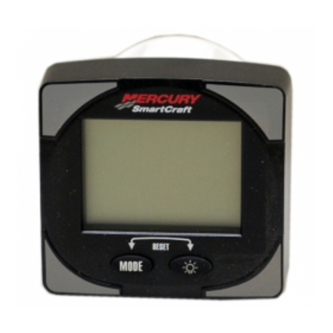
Mercury Axius System User manual

© 2011 Mercury Marine CMD Axius Generation 2 Models *CMD-4082082,/,90-8M0052072* CMD-4082082 / 90-8M0052072 211
Welcome
You have selected one of the finest marine power packages available. It incorporates numerous design features to assure
operating ease and durability.
With proper care and maintenance, you will thoroughly enjoy using this product for many boating seasons. This manual is
a supplement to the Operation, Maintenance, and Warranty Manual included with your engine package and provides
information about the Axius propulsion system. To ensure maximum performance and carefree use, we ask that you
thoroughly read this manual.
This manual contains specific instructions for using and maintaining your product. Keep this manual with the product for
ready reference whenever you are on the water.
Thank you for purchasing one of our products. We sincerely hope your boating will be pleasant!
Warranty Message
The product you have purchased comes with a limited warranty from Mercury Marine or Cummins MerCruiser Diesel;
the terms of the warranty are set forth in the Warranty sections of the Operation, Maintenance and Warranty Manual
included with your power package. The warranty statement contains a description of what is covered, what is not covered,
the duration of coverage, how to best obtain warranty coverage, important disclaimers and limitations of damages and
other related information. Please review this important information.
Read This Manual Thoroughly
IMPORTANT: If you do not understand any portion of this manual, contact your dealer for a demonstration of actual starting
and operating procedures.
Notice
Throughout this publication, and on your power package, dangers, warnings, cautions, and notices, accompanied by the
International Hazard Symbol !, may be used to alert the installer/user to special instructions concerning a particular
service or operation that may be hazardous if performed incorrectly or carelessly. Observe them carefully.
These Safety Alerts alone cannot eliminate the hazards that they signal. Strict compliance with these special instructions
while performing the service, plus common sense operation, are major accident prevention measures.
! DANGER
Indicates a hazardous situation which, if not avoided, will result in death or serious injury.
! WARNING
Indicates a hazardous situation which, if not avoided, could result in death or serious injury.
! CAUTION
Indicates a hazardous situation which, if not avoided, could result in minor or moderate injury.
NOTICE
Indicates a situation which, if not avoided, could result in engine or major component failure.
IMPORTANT: Identifies information essential to the successful completion of the task.
NOTE: Indicates information that helps in the understanding of a particular step or action.
Trademark and Copyright Information
The description and specifications contained herein were in effect at the time this guide was approved for printing. Mercury
Marine, whose policy is one of continuous improvement, reserves the right to discontinue models at any time, or to change
specifications or designs, without notice and without incurring obligation.
Mercury Marine, Fond du Lac, Wisconsin, USA. Printed in USA.
© 2011, Mercury Marine

Mercury, Mercury Marine, MerCruiser, Mercury MerCruiser, Mercury Racing, Mercury Precision Parts, Mercury Propellers,
Mariner, Quicksilver, Alpha, Axius, Bravo One, Bravo Two, Bravo Three, K‑Planes, MerCathode, OptiMax, Precision Pilot, Pro
Max, SeaCore, Skyhook, SmartCraft, Sport‑Jet, Total Command, Verado, VesselView, Zero Effort, Zeus, #1 On The Water, M
with Waves logo, Mercury with Waves logo, and SmartCraft logo are all registered trademarks of Brunswick Corporation. Mercury
Product Protection logo is a registered service mark of Brunswick Corporation.
! WARNING
The operator (driver) is responsible for the correct and safe operation of the boat, the equipment aboard and the safety of all
occupants aboard. We strongly recommend that the operator read this Operation, Maintenance and Warranty Manual and
thoroughly understand the operational instructions for the power package and all related accessories before the boat is used.
! WARNING
The engine exhaust from this product contains chemicals known to the state of California to cause cancer, birth defects or other
reproductive harm.

CMD-4082082 / 90-8M0052072 eng FEBRUARY 2011 Page i
TABLE OF CONTENTS
Section 1 - Getting to Know the Axius System
Features and Controls...............................................................2
Audio Warning System.......................................................2
VesselView.........................................................................2
Instrumentation...................................................................2
Propulsion Personality ...................................................2
VesselView (If Equipped)...............................................3
SC1000 and SC100 Digital Gauges (If Equipped).........3
SmartCraft SC100 System Link Digital Gauges (If
Equipped).......................................................................3
System Link Digital Gauges (If Equipped)......................4
Switches.............................................................................4
Emergency Stop (E‑Stop) Switch.......................................5
Lanyard Stop Switch...........................................................6
Digital Throttle and Shift.....................................................7
Electronic Helm Steering....................................................7
Dual‑Handle Electronic Remote Control (ERC)—Operation
and Adjustment...................................................................7
Operation........................................................................7
Adjustment......................................................................7
Dual Handle Yacht Console Control—Operation and
Adjustment..........................................................................8
Operation........................................................................8
Adjustment......................................................................8
Optional SportFish Electronic Remote Control (ERC)—
Operation and Adjustment..................................................9
Operation........................................................................9
Adjustment......................................................................9
Joystick—Basic Operation................................................12
Operating With an Auxiliary Joystick (If Equipped)...........12
Axius Premier (If Equipped)..............................................12
Section 2 - On the Water
Avoiding Low‑Voltage Conditions............................................16
Getting Started.........................................................................16
Traditional Maneuvering with Steering and Thrust...........16
To Maneuver the Boat in Forward or Reverse.............16
To Steer the Boat in Tight Turns at Low Speeds..........16
To Spin the Boat at Low Speeds..................................16
Maneuvering After Engine or Module Failure...................16
Maneuvering with the Joystick..........................................17
Special Digital Throttle and Shift (DTS) Features.............18
Troll...............................................................................19
Transfer........................................................................19
Dock.............................................................................19
Throttle Only.................................................................20
1 (Single) Lever............................................................21
Sync..............................................................................21
Helm Transfer—Standard Stations..........................................22
Helm Transfer...................................................................22
Requesting Helm Transfer................................................22
Helm Transfer and Precision Pilot....................................23
Helm Transfer—Auxiliary Joystick Stations.............................23
Auxiliary Joystick Station Transfer....................................23
Requesting Transfer to an Auxiliary Joystick Station........23
Requesting Transfer from an Auxiliary Joystick Station...23
Operating Axius Premier (If Equipped)....................................24
Chartplotter Requirements................................................24
Features............................................................................24
Autopilot Screen...............................................................24
Trackpad...........................................................................25
Trackpad Lights................................................................25
Trackpad Buttons with the Power Icon.............................25
Precision Pilot Modes.......................................................26
Skyhook Station Keeping (If Equipped)............................26
Auto Heading....................................................................27
Engaging Auto Heading................................................27
Course Adjustment Using the Turn Buttons or Joystick28
To Resume a Heading .................................................29
Disengaging Auto Heading...........................................30
Track Waypoint.................................................................31
Engaging Track Waypoint Mode..................................32
Disengaging Track Waypoint Mode..............................33
Turn Buttons in Track Waypoint Mode.........................34
Auto Heading Button in Track Waypoint Mode ............34
Acknowledging a Turn During a Waypoint Arrival........34
Waypoint Sequence.....................................................35
Cruise Control...................................................................37
Contingent Operations.............................................................38
Port Engine–Only Operation.............................................38
Axius Shift Override—Emergency Procedure...................38
Transporting an Axius Boat......................................................39
Section 3 - Troubleshooting
Diagnosing Electronically Controlled Fuel System Problems..42
Electrical Connections.............................................................42
Troubleshooting Engine Related Problems.............................42
Check VesselView First...........................................................42
VesselView Malfunction Fault Code List..................................42
Diagnosing DTS Problems.......................................................43
Engine Guardian System.........................................................43
Troubleshooting Charts............................................................44
Standard Helm Joystick....................................................44
Auxiliary Joystick Station (If Equipped) ............................44
Electronic Remote Controls..............................................45
Steering System...............................................................46
Trackpad Features............................................................46
Auto Pilot..........................................................................46

Page ii CMD-4082082 / 90-8M0052072 eng FEBRUARY 2011
Skyhook...........................................................................47
Section 4 - Customer Assistance Information
Owner Service Assistance......................................................50
Local Repair Service.........................................................50
Service Away From Home................................................50
Stolen Power Package..................................................... 50
Attention Required After Submersion............................... 50
Replacement Service Parts.............................................. 50
Parts and Accessories Inquiries....................................... 50
Resolving a Problem.........................................................50
Ordering Literature................................................................. 51
United States and Canada................................................51
Outside the United States and Canada............................ 51
Section 5 - Predelivery and Customer Delivery Checklists
Pre‑Delivery Information.........................................................54
Dealer Pre‑Delivery Checklist for Axius Products (Before
Delivery to the Customer).......................................................54
Skyhook (If Equipped)...................................................... 54
Before Starting—Key Off.................................................. 54
Before Starting—Key On.................................................. 55
Engines Running at the Dock........................................... 55
Sea Trial........................................................................... 55
After On Water Test..........................................................55
Skyhook (If Equipped)...................................................... 56

Section 1 - Getting to Know the Axius System
CMD-4082082 / 90-8M0052072 eng FEBRUARY 2011 Page 1
Section 1 - Getting to Know the Axius System
Table of Contents
Features and Controls............................................................ 2
Audio Warning System....................................................2
VesselView......................................................................2
Instrumentation................................................................2
Propulsion Personality ............................................ 2
VesselView (If Equipped) ........................................ 3
SC1000 and SC100 Digital Gauges (If Equipped)
................................................................................ 3
SmartCraft SC100 System Link Digital Gauges (If
Equipped) ................................................................ 3
System Link Digital Gauges (If Equipped) ............... 4
Switches..........................................................................4
Emergency Stop (E‑Stop) Switch....................................5
Lanyard Stop Switch........................................................6
Digital Throttle and Shift..................................................7
Electronic Helm Steering.................................................7
Dual‑Handle Electronic Remote Control (ERC)—
Operation and Adjustment...............................................7
Operation ................................................................. 7
Adjustment .............................................................. 7
Dual Handle Yacht Console Control—Operation and
Adjustment.......................................................................8
Operation ................................................................. 8
Adjustment .............................................................. 8
Optional SportFish Electronic Remote Control (ERC)—
Operation and Adjustment...............................................9
Operation ................................................................. 9
Adjustment .............................................................. 9
Joystick—Basic Operation.............................................12
Operating With an Auxiliary Joystick (If Equipped)........12
Axius Premier (If Equipped)...........................................12
1

Section 1 - Getting to Know the Axius System
Page 2 CMD-4082082 / 90-8M0052072 eng FEBRUARY 2011
Features and Controls
Audio Warning System
Your Cummins MerCruiser Diesel power package may be equipped with an audio warning system. The audio warning system is
designed to warn the operator that a malfunction has occurred and will not protect the engine from damage.
IMPORTANT: If the audio warning sounds, stop the engine immediately if you are not in a hazardous situation. Investigate the
cause and correct it, if possible. If you cannot determine the cause, consult your Cummins MerCruiser Diesel Authorized Repair
Facility. Operating the vessel with a critical fault malfunction may cause engine, drive, and control system damage.
The audio warning will sound if the engine control module (ECM) detects a malfunction. Malfunction fault code information can
be displayed on the following SmartCraft instruments:
• VesselView
• System tachometer or speedometer
Audio Warning Tones
Critical Faults
• Six long (1.5 second) beeps at 1/2 second intervals
• 2 minute pause followed by
• One long (1.5 second) beep every two minutes until the fault is corrected
Non‑critical fault
• Six short (0.5 second) beeps at 1/2 second intervals
• There will be no additional warning tones
IMPORTANT: Fault codes generated by a malfunction will remain in the system until corrected and cleared.
VesselView
Refer to your VesselView operations manual for detailed engine monitoring information.
Instrumentation
Propulsion Personality
The propulsion personality was developed by Cummins MerCruiser Diesel (CMD) and your boat builder to ensure that vessel
performance regarding joystick, steering, and autopilot work optimally for your vessel in ideal conditions. As conditions vary, such
as wind and current, additional user input may be required to compensate.
Changing engine performance, gear ratios, or propeller may affect the performance of the joystick as well as the top speed of the
vessel. Changing any parameter from the original factory equipment and settings can have a negative affect on performance, and
changes should not be made without consulting the OEM (boat manufacturer) and a CMD Application Engineer first.
The vessel personality is the property of the OEM, and any changes or upgrades to the personality must be approved and
distributed by the OEM. CMD will assist with software personality changes only at the request of the OEM.

Section 1 - Getting to Know the Axius System
CMD-4082082 / 90-8M0052072 eng FEBRUARY 2011 Page 3
VesselView (If Equipped)
Your power package may be connected to a SmartCraft VesselView display. The interactive VesselView display continuously
reports real‑time information about speed and performance, engine or drive system fault codes, fuel status, water temperature
and depth (when connected through the chart plotter), and other operating data. When VesselView detects a problem with any
connected system, it displays an alarm message to the boat operator.
27198
VesselView
VesselView may also be connected to other vessel systems such as GPS, generators, and cabin environmental controls. This
vessel integration allows the operator to monitor and control a wide range of vessel systems from a single display.
Refer to the VesselView Operator's Manual for more information.
SC1000 and SC100 Digital Gauges (If Equipped)
The SmartCraft SC1000 and SC100 digital gauges complement VesselView. Refer to the SC1000 and SC100 Digital Gauge
Operator's Manual for more information.
Typical SC1000 gauges
a - Tachometer
b - Speedometer
c - LCD System View display
SmartCraft SC100 System Link Digital Gauges (If Equipped)
The Cummins MerCruiser Diesel SmartCraft instrument package augments the information provided by VesselView. The
instrument package may display:
• Engine RPM
• Boat speed
• Coolant temperature
• Oil pressure
• Battery voltage
• Fuel consumption
24575
a
b
c
c

Section 1 - Getting to Know the Axius System
Page 4 CMD-4082082 / 90-8M0052072 eng FEBRUARY 2011
• Engine operating hours
• And more
44348
Typical SmartCraft SC100 System Link Gauge tachometer (speedometer similar)
For basic operation information on the SmartCraft instruments, refer to the manual provided with your gauge.
System Link Digital Gauges (If Equipped)
Some instrumentation packages include gauges that augment the information provided by VesselView and the SmartCraft
tachometer and speedometer. The owner and operator should be familiar with all the instruments and their functions on the boat.
Because of the large variety of instrumentation and manufacturers, have your boat dealer explain the gauges and normal readings
that appear on your boat.
The following type of digital gauge may be included with your power package.
ab
c
d
44347
Typical multi-function digital gauge
Item Gauge Indicates
a Oil pressure Engine oil pressure
b Water temperature Engine operating temperature
c Voltmeter Battery voltage
d Fuel level Quantity of fuel in tank
Switches
38160
Four position key switch
•"OFF" In the "OFF" position, all electrical circuits are off. The engine will not operate with the key switch in the "OFF" position.

Section 1 - Getting to Know the Axius System
CMD-4082082 / 90-8M0052072 eng FEBRUARY 2011 Page 5
•"ACC" In the "ACC" position, any accessory connections to the electrical circuits can be operated. The engine will not operate
with the key switch in the "ACC" position.
•"ON" In the "ON" position, all electrical circuits and instrumentation receive power. The engine can be started with an optional
start stop switch.
•"START" Turn the key to the start position and release to start the engine.
NOTE: The key can only be removed with the key switch in the "OFF" position.
28082
Dual engine start-stop switch
A start‑stop switch is optional equipment. The start‑stop switch works in conjunction with the key switch. There is one start‑stop
switch for each engine. Each button on a multi‑engine start‑stop switch functions independently. The key switch must be in the
run position to start a stopped engine with the the start‑stop switch. Pressing a start‑stop switch button when an engine is running
will shut down the corresponding engine.
Emergency Stop (E‑Stop) Switch
The emergency stop (E‑stop) switch turns off the engines in an emergency situation, such as a person overboard or tangled
propeller. When activated, the E‑stop switch interrupts the power supply to the main power relay, including power to the gauges,
steering, and accessories.
34014
a
Activation of the E‑stop switch stops the engines immediately. The boat will continue to coast for some distance however. This
distance depends upon boat velocity and the degree of any turn in progress at the time of shutdown. However, the boat should
not complete a full circle. While the boat is coasting, it can cause injury to anyone in the boat's path as seriously as the boat would
when under power.
We recommend instructing other occupants on proper starting and operating procedures should they need to operate the engine
in an emergency.
Accidental or unintended activation of the switch during normal operation is also possible, potentially causing hazardous situations
that include:
• Occupants can be thrown forward due to unexpected loss of forward motion, a particular concern for passengers in the front
of the boat who could be ejected over the bow and possibly struck by the propulsion or steering components.
• Operator can lose power and directional control in heavy seas, strong current, or high winds.
• Operator can lose control when docking.

Section 1 - Getting to Know the Axius System
Page 6 CMD-4082082 / 90-8M0052072 eng FEBRUARY 2011
Restarting an engine using the key switch or start button after an E‑stop shutdown without first turning the key switch to the off
position for at least 30 seconds will restart the engine but cause fault codes to be set. Unless you are in a potentially hazardous
situation, turn the key switch off and wait at least 30 seconds before restarting an engine. Contact your Authorized Cummins
MerCruiser Diesel Repair Facility if fault codes are still displayed after restarting.
Lanyard Stop Switch
The purpose of a lanyard stop switch is to turn off the engine when the operator moves outside the operator's position (as in
accidental ejection from the operator's position).
a - Stop switch
b - Lanyard
c - Clips to the operator
Accidental ejections, such as falling overboard, are more likely to occur in:
• low‑sided sport boats
• bass boats
• high performance boats
Accidental ejections can also occur from:
• poor operating practices
• sitting on the seat or gunwale at planing speeds
• standing at planing speeds
• operating at planing speeds in shallow or obstacle infested waters
• releasing your grip on the steering wheel that is pulling in one direction
• consuming alcohol or drugs
• high speed boating maneuvers
The lanyard is a cord usually between 122 and 152 cm (4 and 5 ft) in length when stretched out, with an element on one end made
to be inserted into the switch and a snap on the other end for attaching to the operator. The lanyard is coiled to make its at‑rest
condition as short as possible to minimize the likelihood of lanyard entanglement with nearby objects. Its stretched‑out length is
made to minimize the likelihood of accidental activation should the operator choose to move around in an area close to the normal
operator's position. If it is desired to have a shorter lanyard, wrap the lanyard around the operator's wrist or leg, or tie a knot in
the lanyard.
Activation of the lanyard stop switch will stop the engine immediately, but the boat will continue to coast for some distance
depending upon the velocity and degree of any turn at shut down. However, the boat will not complete a full circle. While the boat
is coasting, it can cause injury to anyone in the boat's path as seriously as the boat would when under power.
We strongly recommend that other occupants be instructed on proper starting and operating procedures should they be required
to operate the engine in an emergency (e.g. if the operator is accidentally ejected).
! WARNING
If the operator falls out of the boat, stop the engine immediately to reduce the possibility of serious injury or death from being
struck by the boat. Always properly connect the operator to the stop switch using a lanyard.
Accidental or unintended activation of the switch during normal operation is also a possibility. This could cause any, or all, of the
following potentially hazardous situations:
• Occupants could be thrown forward due to unexpected loss of forward motion, a particular concern for passengers in the front
of the boat who could be ejected over the bow and possibly struck by the propulsion or steering components.
• Loss of power and directional control in heavy seas, strong current or high winds.
• Loss of control when docking.
! WARNING
Avoid serious injury or death from deceleration forces resulting from accidental or unintended stop switch activation. The boat
operator should never leave the operator's station without first disconnecting the stop switch lanyard from the operator.
74608
RUN
a
b
c

Section 1 - Getting to Know the Axius System
CMD-4082082 / 90-8M0052072 eng FEBRUARY 2011 Page 7
Digital Throttle and Shift
Digital Throttle and Shift (DTS) operating instructions are provided in a separate manual. Refer to Cummins MerCruiser Diesel's
SmartCraft and DTS Operators Manual.
Electronic Helm Steering
The electronic helm steering operates using electrical signals. A computer‑controlled electric motor attached to the steering wheel
simulates the resistance feedback found in hydraulic steering systems.
We recommend that you drive carefully (in an open area clear of obstructions or other boat traffic) until you are familiar with the
Axius system's handling characteristics and the boat's response. The electronic steering may provide a faster steering response
than expected.
To confirm your steering range from lock to lock, ensure that the starboard engine key switch is on. The engines do not have to
be running. Turn the wheel to starboard until the wheel stops at the starboard lock or end‑stop. The end‑stop is electronically set
by the electric motor attached to the steering wheel. Begin turning the wheel to port and count the number of revolutions until the
wheel stops at the port lock. The number of wheel revolutions you counted moves the drives from the maximum starboard angle
to maximum port angle, with the center (straight‑ahead position) being 0°. The maximum steering angles are controlled within the
vessel personality developed by CMD and the OEM.
In certain situations the electronic end‑stops of the wheel are not felt. The absence of noticeable end‑stops does not affect the
steering. The drives will still stop when they reach the full turn position at each lock. The absence of end‑stops can be the result
of the starboard key switch in the off position, a low starboard battery voltage, or a steering wheel motor fault.
Your vessel's personality, as developed by the vessel manufacturer in partnership with CMD, determines the number of turns lock
to lock. Typically, this is approximately 2‑3/4 revolutions of the wheel. The OEM may request different lock to lock settings for
other boat models.
Dual‑Handle Electronic Remote Control (ERC)—Operation and Adjustment
Operation
The electronic remote control (ERC) handle controls the operation of shift and throttle. Push the control handle forward from neutral
to the first detent for forward gear. Continue pushing the handle forward to increase speed. Pull the control handle from the forward
position to the neutral position to decrease speed and eventually stop. Pull the control handle back from neutral to the first detent
for reverse gear. Continue pulling the handle back to increase speed in reverse.
NOTE: In certain modes, gear position is determined by the Electronic Shift Control (ESC), not the position of the ERC levers.
When using the joystick or while in Skyhook, the computer moves the drives in and out of gears even though the handles are in
neutral.
Typical ERC handles
a - Forward
b - Neutral
c - Reverse
d - Starboard engine handle
e - Port engine handle
The amount of force needed to move the ERC handles and to move the ERC handles through the detents is adjustable to help
prevent unwanted motion of the handle in rough water.
Adjustment
NOTE: The control handle tension and detent tension may require period maintenance using the adjustment screws.
To adjust the ERC handle detent tension:
1. Remove the side cover of the handle needing adjustment.
2. Turn the adjustment screw clockwise to increase tension on the control handle and counter‑clockwise to decrease tension.
3. Adjust to tension desired.
c
b
a
d
e
39308

Section 1 - Getting to Know the Axius System
Page 8 CMD-4082082 / 90-8M0052072 eng FEBRUARY 2011
To adjust ERC handle tension:
1. Remove the side cover of the handle needing adjustment.
2. Turn the adjustment screw clockwise to increase tension on the control handle and counter‑clockwise to decrease tension.
3. Adjust to tension desired.
Starboard side cover removed, port similar
a - Detent tension adjustment screw, labeled
"De"
b - Handle tension adjustment screw, labeled
"Fr"
Dual Handle Yacht Console Control—Operation and Adjustment
Operation
Operation of shift and throttle is controlled by the movement of the control handle. Push the control handle forward from neutral
to the first detent for forward gear. Continue pushing the handle forward to increase speed. Pull the control handle back from
neutral to the first detent for reverse gear. Continue pulling the handle back to increase speed.
24559
F
N
R
78O
78O
Adjustment
1. Control handle tension adjustment screw ‑ This screw can be adjusted to increase or decrease the tension on the control
handle (cover must be removed). This will help prevent unwanted motion of the handle in rough water. Turn the screw
clockwise to increase tension and counterclockwise to decrease tension. Adjust to tension desired.
28087
a
b

Section 1 - Getting to Know the Axius System
CMD-4082082 / 90-8M0052072 eng FEBRUARY 2011 Page 9
2. Detent tension adjustment screw ‑ This screw can be adjusted to increase or decrease the effort to move control handle out
of detent positions (cover must be removed). Turning the screw clockwise will increase tension. Adjust to tension desired.
a - Detent tension adjustment
b - Control handle tension adjustment
Optional SportFish Electronic Remote Control (ERC)—Operation and Adjustment
Operation
Operation of shift and throttle is controlled by the movement of the control handle. Push the control handle forward from neutral
to the first detent for forward gear. Continue pushing forward to increase speed. Pull the control handle back from neutral to the
first detent for reverse gear. Continue pulling back to increase speed.
NOTE: In certain modes, gear position is determined by the Electronic Shift Control (ESC), not the position of the ERC levers.
When using the joystick or while in Skyhook, the computer moves the drives in and out of gears even though the handles are in
neutral.
a - Neutral
b - Forward (port mounted handle). reverse (starboard mounted handle)
c - Forward (starboard mounted handle). reverse (port mounted handle)
The amount of force needed to move the ERC handle and to move the ERC handle through the detents is adjustable to help
prevent unwanted motion of the handle in rough water.
Adjustment
NOTE: The control handle tension and detent tension may require period maintenance using the adjustment screws.
To adjust the ERC handle tension or detent tension:
1. Insert a suitable tool in the slot at the bottom of the emblem cover and pry the cover off.
a - Side cover (port mounted handle)
b - Handle
c - Emblem cover
d - Slot
24543
b
a
b
c
45913
a
b
a
c
b
d
43425
b

Section 1 - Getting to Know the Axius System
Page 10 CMD-4082082 / 90-8M0052072 eng FEBRUARY 2011
2. Remove the M8 screw and washer securing the handle.
41350
Location of handle screw and washer
3. Remove the handle.
4. Remove the three M5 screws securing the side cover.
41347
Location of side cover screws
5. Remove the side cover.
6. For adjustment, temporarily install the handle, washer and screw. Finger‑tighten the screw.
7. To adjust the ERC handle detent tension:
a. Turn the adjustment screw clockwise to increase tension on the control handle and counter‑clockwise to decrease
tension.
b. Adjust to the desired tension.
8. To adjust ERC handle tension:
a. Turn the adjustment screw clockwise to increase tension on the control handle and counter‑clockwise to decrease
tension.

Section 1 - Getting to Know the Axius System
CMD-4082082 / 90-8M0052072 eng FEBRUARY 2011 Page 11
b. Adjust to the desired tension.
Side cover removed
a - Detent tension adjustment screw
b - Handle tension adjustment screw
9. Remove the screw, washer, and handle when the adjustments are complete.
10. Install the side cover. Secure the cover with the three M5 x 10 mm long screws. Tighten the screws to specification.
Description Nm lb‑in. lb‑ft
Side cover screws 3.4 30 –
11. Apply adhesive to the threads of the handle screw.
Tube Ref No. Description Where Used Part No.
7Loctite 271 Threadlocker Threads of handle screw 92-809819
12. Install the washer and the M8 x 45 mm long screw. Tighten the screw to specification.
41350
Location of handle screw and washer
Description Nm lb‑in. lb‑ft
Handle screw 28.2 – 21
ab
41340

Section 1 - Getting to Know the Axius System
Page 12 CMD-4082082 / 90-8M0052072 eng FEBRUARY 2011
13. Install the emblem cover on the handle.
a - Side cover
b - Handle
c - Emblem cover
d - Slot
Joystick—Basic Operation
The joystick offers intuitive control of your boat during low speed and docking maneuvers. Engine speed is limited from idle to
approximately 1700‑2500 RPM in this mode, depending on vessel and propulsion application, to prevent excessive prop wash or
unacceptable boat dynamics during maneuvers. DOCK mode reduces this upper range to approximately 1000‑1200 RPM and
will be discussed more in the DOCK mode section. This RPM range is mainly due to engine horsepower. The levers must be used
for vessel maneuvering if environmental conditions require more thrust than the range listed above.
45887
Joystick and typical location
Though joystick operation is easy and intuitive, you should avoid using it until you have the opportunity to become familiar with
the vessel's handling characteristics while operating the vessel with the joystick in open water. Thereafter, you should occasionally
practice operating without the joystick in case the joystick becomes inoperable.
Both engines must be running and both ERC levers must be in neutral for the joystick to operate.
Operating With an Auxiliary Joystick (If Equipped)
An auxiliary joystick located at a separate station called an auxiliary joystick station offers the same control of the boat as does a
helm joystick. The operator may transfer to an auxiliary joystick station after meeting certain control requirements at the main
helm.
There may be multiple auxiliary joystick stations located on the vessel. Each auxiliary joystick station is equipped with a joystick,
an E‑stop switch, and a control pad.
The auxiliary joystick station control pad includes:
• Indicator lights for drive train status (two lights for dual)
• A fault (alarm) indicator light and horn
• A transfer button equipped with an indicator light
Refer to Section 2—On the Water for additional information.
Axius Premier (If Equipped)
The Axius Premier system is a fully‑integrated operation and navigation system. No aftermarket autopilot is necessary.
Axius Premier utilizes the following:
b
a
c
b
d
43425
b

Section 1 - Getting to Know the Axius System
CMD-4082082 / 90-8M0052072 eng FEBRUARY 2011 Page 13
• CAN based navigational information from a GPS unit
• An approved NMEA0183 equipped chartplotter
• CAN based navigational information from an inertial measurement unit (IMU)
• CAN based Precision Pilot trackpad
• VesselView
! WARNING
Avoid serious injury from collision with other boats, running aground, or striking objects in the water. Always maintain a diligent
lookout while the boat is operating in any Precision Pilot mode. The Precision Pilot system cannot react to avoid other boats,
shallow water, or objects in the water.
The Axius Premier Precision Pilot trackpad gives the operator control over the following modes:
•Skyhook—allows the boat to hold a position without lines or anchor
NOTE: The Skyhook feature is available pending boat manufacturer personality configuration. Some boat manufacturers do
not enable Skyhook from the factory. Other boats have external notification devices (installed and manufactured by the boat
builder) indicating the vessel is in Skyhook.
•Auto Heading—steers the boat on a fixed compass heading
•Track Waypoint—automatically pilots the boat on a predetermined route from the chart plotter or GPS unit. This can be a
single waypoint, or a series of waypoints assembled into a route. If following a route, at each waypoint transition, the system
will sound an alarm, which must be acknowledged before the boat will proceed to the next waypoint.
•Waypoint Sequence—similar to Track Waypoint, except the system will sound an alarm upon arriving at a waypoint and
transition automatically to the next waypoint on the route.
a - Skyhook
b - Turn to starboard
c - Waypoint Sequence
d - Not used
e - Track Waypoint
f - Auto Heading
g - Resume
h - Turn to port
The buttons on the Precision Pilot trackpad have the following functions:
43573
a
b
c
d
e
f
g
h

Section 1 - Getting to Know the Axius System
Page 14 CMD-4082082 / 90-8M0052072 eng FEBRUARY 2011
Function Description
Skyhook
Engages and disengages Skyhook. Mode is only available when the joystick is centered, both engines are
running, G.P.S. and heading sensors are available, the boat is stationary, and levers are in neutral. Skyhook
can become active while drifting. The Skyhook light will flash until the boat slows itself down, then become solid
when Skyhook is set. For example, if you are drifting forward and press Skyhook, the drives will go to reverse
to slow the vessel. You may still drift forward. When the boat slows its self down, it will enable Skyhook. Skyhook
will not activate if the boat is underway.
Turn < and > Each press of the button causes a 10 degree course change in auto heading. Holding the joystick port or
starboard (until the beep) initiates a one degree change in course. It affects no other autopilot features.
Waypoint
Sequence
Engages Waypoint Sequence, driving the boat on a course set with multiple waypoints on the chart plotter. The
waypoints must be on a route. See the chart plotter owners manual. Waypoint Sequence is available when the
"WAYPOINT SEQUENCE" button is pressed, and data (a NMEA‑0183 stream) is available from a chart plotter,
and the GPS and heading sensor signals are available. Waypoint sequence will follow a route automatically,
announcing arrival at each waypoint and then turning towards the next waypoint. Track Waypoint must be
enabled first then select Waypoint Sequence.
Track
Waypoint
Route Tracking is available when data (NMEA0183 stream) is available from a chart plotter, GPS, and heading
sensor signals are available. The boat will attempt to steer to a waypoint or a route from the chart plotter. Arrival
at the waypoint must be acknowledged before the vessel will proceed to the next waypoint along the route.
Auto
Heading
Engages Auto Heading mode, which will hold the boat on a fixed course at the speed that the operator chooses.
Heading control is available when the "Auto Heading" button is pressed, GPS and IMU signals are available.
(See "Turn < and >" for course adjustment information.) A chart plotter not needed for this feature.
Resume Resumes previous Auto Heading course if the boat's direction has not been changed 90° or more.
NOTE: Moving the steering wheel will always take control of the boat. A slight detent will have to be overcome to give the operator
feedback that the they are taking control from the Precision Pilot. Changing gears using the electronic remote control (ERC) lever
will also disable the autopilot mode.

Section 2 - On the Water
CMD-4082082 / 90-8M0052072 eng FEBRUARY 2011 Page 15
Section 2 - On the Water
Table of Contents
Avoiding Low‑Voltage Conditions......................................... 16
Getting Started..................................................................... 16
Traditional Maneuvering with Steering and Thrust........16
To Maneuver the Boat in Forward or Reverse ...... 16
To Steer the Boat in Tight Turns at Low Speeds ..16
To Spin the Boat at Low Speeds ........................... 16
Maneuvering After Engine or Module Failure................16
Maneuvering with the Joystick.......................................17
Special Digital Throttle and Shift (DTS) Features..........18
Troll ....................................................................... 19
Transfer ................................................................. 19
Dock ...................................................................... 19
Throttle Only .......................................................... 20
1 (Single) Lever ..................................................... 21
Sync ...................................................................... 21
Helm Transfer—Standard Stations....................................... 22
Helm Transfer................................................................22
Requesting Helm Transfer.............................................22
Helm Transfer and Precision Pilot.................................23
Helm Transfer—Auxiliary Joystick Stations.......................... 23
Auxiliary Joystick Station Transfer.................................23
Requesting Transfer to an Auxiliary Joystick Station.....23
Requesting Transfer from an Auxiliary Joystick Station
.......................................................................................23
Operating Axius Premier (If Equipped)................................. 24
Chartplotter Requirements.............................................24
Features.........................................................................24
Autopilot Screen............................................................24
Trackpad........................................................................25
Trackpad Lights.............................................................25
Trackpad Buttons with the Power Icon..........................25
Precision Pilot Modes....................................................26
Skyhook Station Keeping (If Equipped).........................26
Auto Heading.................................................................27
Engaging Auto Heading ........................................ 27
Course Adjustment Using the Turn Buttons or Joystick
.............................................................................. 28
To Resume a Heading ......................................... 29
Disengaging Auto Heading .................................... 30
Track Waypoint..............................................................31
Engaging Track Waypoint Mode ........................... 32
Disengaging Track Waypoint Mode ...................... 33
Turn Buttons in Track Waypoint Mode .................. 34
Auto Heading Button in Track Waypoint Mode .... 34
Acknowledging a Turn During a Waypoint Arrival . 34
Waypoint Sequence .............................................. 35
Cruise Control................................................................37
Contingent Operations.......................................................... 38
Port Engine–Only Operation..........................................38
Axius Shift Override—Emergency Procedure................38
Transporting an Axius Boat.................................................. 39
2

Section 2 - On the Water
Page 16 CMD-4082082 / 90-8M0052072 eng FEBRUARY 2011
Avoiding Low‑Voltage Conditions
Batteries will discharge when the vessel is not regularly operated. Low voltage may cause faults for the control modules on the
vessel and may cause the steering cylinder to not function. Ensure the batteries remain fully charged at all times. Use one of the
following devices to keep the batteries charged when the vessel is not in regular use.
•Trickle charger— trickle chargers are better at maintaining batteries when the vessel is not in use. Make sure the charger
is set for your specific battery type (flooded lead acid, absorbed glass mat, etc), if equipped with settings for battery types.
•Battery charger—if equipped, use a battery charger connected to shore power. Refer to the boat owner’s manual for proper
operation.
The nominal "no load" (no electrical loads present, no charging or discharging, the battery is essentially on an open circuit) battery
voltage, when fully charged, should be 12.5 to 12.6 VDC. Check the voltage after starting the engines and prior to leaving the
dock. Do not leave the dock if battery voltage is below 12.0 VDC
If on the water and battery voltage drops below 12.0 VDC, get the battery voltage back up above 12.0 VDC by doing the following:
• Turn off any unnecessary electrical loads.
• If equipped and operating conditions allow, start the generator set.
• If possible, raise the RPM of the engine(s).
• If operating conditions allow, increase engine(s) above idle RPM(1000‑1200 RPM should be sufficient). If in gear, boat speed
and wake will increase. .
• If conditions do not allow an increase in boat speed (no wake zone), then put one engine in throttle only mode (1000‑1200
RPM) and increase other engine speed to maintain boat speed.
Alarms will set if voltage drops below 10.5 VDC, and the drives will lock at 9.5 VDC. It is possible to have a drive lock at a higher
voltage if there is a very high demand for steering and the batteries cannot meet that demand. If the steering locks due to battery
voltage, the battery condition must improve to a voltage above 10.5 V and the keyswitch on the affected side turned off and then
on to reset the device. Note that cranking the engine will cause a significant short term drop in battery voltage.
Getting Started
Traditional Maneuvering with Steering and Thrust
IMPORTANT: The Axius steering system requires fluid pressure created by a engine‑driven hydraulic pump to turn the drives.
You can not steer the Axius system without the engines running.
You can maneuver your Axius‑equipped vessel much like a traditional sterndrive boat. However, the Axius drive system expands
the maneuvering capability of your vessel at both slow and planing speeds. At slow speeds, the drive system is capable of directing
the thrust through independently articulating drives to produce more responsive turning of the vessel. The Axius drive system
features counter‑rotating propellers that do not produce any propsteer when accelerating or slowing down.
To Maneuver the Boat in Forward or Reverse
Place one or both engines in forward or reverse gear and steer with the steering wheel as you would any comparable boat.
To Steer the Boat in Tight Turns at Low Speeds
• To turn the boat in tight turns at low speeds, turn the wheel in the direction of the turn.
• To increase the turn rate of the boat after the wheel is completely turned, you may increase the power to the inside drive.
To Spin the Boat at Low Speeds
• Turn the drives to straight forward.
• To spin starboard (to the right), place the starboard engine in reverse and the port engine in forward.
• To spin port (to the left), place the port engine in reverse and the starboard engine in forward.
• To increase the rate of turn, simultaneously adjust each ERC lever for more throttle. More reverse throttle will be needed to
compensate for the forward drive.
Maneuvering After Engine or Module Failure
If an engine, helm, or steering module stops functioning during use, the remaining drive may have an electronic limit while turning
inboard. This limit is to remove the possibility of the drives making contact with each other, since the active drive is unable to
determine the position of the disabled drive. The boat is still operational, but maneuverability is decreased when turning toward
the drive that is not working. The drive is still capable of turning through the full range when turning away from the disabled drive.
Use extra caution when one drive is disabled.
Other manuals for Axius System
2
Table of contents
Other Mercury Boating Equipment manuals