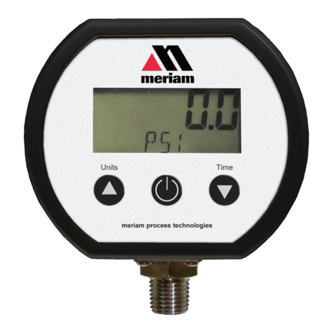
Meriam meriGauge Plus User manual

Copyright © 2016 Meriam®
The meriGauge plus system
The meriGauge®plus and meriSense
meriLink™ software
A meriSense™ smart sensor
1.888.610.7664info@Meriam-Direct.com

9R479-IR April 2016
meriGauge plus System User Manual 2
Introductory information
Notification Statements
Disclaimer
Every precaution has been taken in the preparation of this
manual. Nevertheless, Meriam assumes no responsibility for
errors or omissions or any damages resulting from the use of
the information contained in this publication, including,
without limitation, incidental, special, direct or consequential
damages. MERIAM MAKES NO REPRESENTATIONS OR
WARRANTIES WITH RESPECT TO THE ACCURACY OR
COMPLETENESS OF THE CONTENTS HEREOF AND
SPECIFICALLY DISCLAIMS ANY IMPLIED WARRANTIES
OF MERCHANTABILITY OR FITNESS FOR ANY
PARTICULAR PURPOSE. Meriam reserves the right to revise
this publication and to make changes from time to time in the
content hereof without obligation to notify any person of such
revision or changes.
In no event shall Meriam be liable for any indirect, special,
incidental, consequential, or punitive damages or for any lost
profits arising out of or relating to any services provided by
Meriam or its affiliates.
It is not possible for Meriam to identify all foreseeable uses or
misuses, therefore all persons involved in commissioning,
using, or maintaining this product must satisfy their self that
each intended application is acceptable.
Copyright
This publication is proprietary to Meriam and no ownership
rights are transferred. Neither this manual, nor any of the
material contained herein, may be reproduced without the prior
written consent of Meriam.
1.888.610.7664info@Meriam-Direct.com

9R479-IR April 2016
meriGauge plus System User Manual 3
Trademark information
Trademarks statements
meriGauge® plus, meriSense™, and meriLink™ are trademarks of
Meriam.
All other trademarks are the property of their respective
owners.
Safety Information
Preventing injury
Failure to follow all instructions could result in injury:
•Read.
•Understand.
•Follow all safety warnings and instructions provided with
this product.
•Meet or exceed your employer’s safety practices.
Safety Symbols
The following table defines the safety symbols, signal words,
and corresponding safety messages used in the manual. These
symbols:
•Identify potential hazards.
•Warn you about hazards that could result in personal
injury or equipment damage.
1.888.610.7664info@Meriam-Direct.com

9R479-IR April 2016
meriGauge plus System User Manual 4
Safety Symbols
Safety Symbols Explaining the symbols
This is the
Read Instruction Manua
l symbol. This symbol
indicates that you must read the instruction manual.
Indicates a potentially hazardous situation which, if not avoided,
will result in death or serious injury.
Indicates a potentially hazardous situation which, if not avoided,
could result in death or serious injury.
Indicates a potentially hazardous situation which, if not avoided,
could result in minor or moderate injury.
Indicates information essential for proper product installation,
operation or maintenance.
General Purpose
General Purpose use only
•Never use General Purpose gauges in hazardous areas.
•Never use General Purpose sensors in hazardous areas.
•General Purpose gauges and sensors are a fire or explosion
hazard.
•Do not substitute components because they may impair
operation and safety.
1.888.610.7664info@Meriam-Direct.com

9R479-IR April 2016
meriGauge plus System User Manual 5
Sample labels for General Purpose gauges
General Purpose—meriGauge plus label
See the figure of a sample General Purpose label.
General Purpose—meriSense Absolute label
See the figure of a sample General Purpose label below.
General Purpose—meriSense Compound label
See the sample General Purpose figure label below.
Serial Number
Model Number
Serial Number
Model Number
Serial Number
Model Number
1.888.610.7664info@Meriam-Direct.com

9R479-IR April 2016
meriGauge plus System User Manual 6
Contents
Introductory information
..................................2
Notification Statements......................2
Trademark ...........................................3
Safety Information ..............................3
Safety Symbols....................................4
General Purpose .................................4
Sample labels for General Purpose
gauges .................................................5
Meriam Contact Information ..............7
Glossary ...............................................8
The meriSense detachable sensors
................9
Make a pressure connection..............9
Protect your sensors from dust ..........9
Accuracy Statement for meriSense
(MS700x-xxxxxx)................................10
Accuracy Statement (continued)......11
Pressure reference chart..................12
Inspect the vent on the sensors.......13
The meriGauge
plus
gauge
............................14
Batteries ............................................14
Batteries (continued) ........................15
Connect the gauge to a sensor ........15
The display.........................................16
Backlight in the LCD display .............17
Display modes ...................................17
Zero the meriGauge plus in Display
mode ..................................................18
The Data Log mode...........................19
List of Engineering Units...................20
Information key .................................21
Auto Off (Automatic shutoff).............21
Prepare the meriGauge plus for
storage...............................................22
The meriLink software
.................................. 23
Installation instructions for meriLink
........................................................... 23
Part 1: Install USB device drivers .... 23
Part 2: Install USB device drivers .... 24
Overview of meriLink........................ 25
Connection status ............................ 27
Buttons.............................................. 28
Passwords......................................... 29
Passwords (continued)..................... 30
Request a recovery password ......... 30
User Calibration—For qualified
personnel only .................................. 31
Configuration for meriGauge plus ... 32
Configuration for meriSense............ 33
Preview the data log......................... 34
Data log files..................................... 35
Data log files (continued)................. 36
Appendices
................................................... 37
Returning for repair or calibration .. 37
Troubleshooting Checklist ............... 38
Specifications ................................... 39
Hazardous Material and Recycling
Compliance....................................... 40
Part numbers .................................... 41
1.888.610.7664info@Meriam-Direct.com

9R479-IR April 2016
meriGauge plus System User Manual 7
1.888.610.7664info@Meriam-Direct.com

9R479-IR April 2016
meriGauge plus System User Manual 8
Glossary
Words and phrases Definitions
Absolute Isolated pressure
(AI)
Absolute pressure is equal to the sum of these two:
1. Gauge pressure.
2. Atmospheric pressure
(also known as barometric pressure).
Button or key •A
button
always refers to an area on the screen that you can
click to select functionality.
•A
key
always refers to hardware push-buttons on the keyboard
that you can press.
Compound Isolated pressure
(CI)
A compound gauge can display both positive and negative
(vacuum) pressures. The meriGauge plus System replaces the
need for buying one gauge for each sensor:
1. A pressure sensor.
2. A vacuum sensor.
Firmware Firmware is a type of software that is stored on hardware. Both
meriGauge plus and meriSense have firmware. meriLink is a
software application that can communicate with their firmware and
change or update it as needed.
Isolated The word isolated refers to the sensing element being isolated
from the media. It is commonly used in the phrases Absolute
Isolated (AI) pressure and Compound Isolated (CI) pressure.
Meriam Calibration Meriam calibration refers to any calibration completed at Meriam
with Meriam traceability. Meriam calibration includes:
•Oven calibration.
•Multipoint Meriam adjustment.
User Calibration User calibration refers to any calibration done outside of Meriam
with non-Meriam traceability. User calibration includes:
•Multipoint user calibration or adjustment.
1.888.610.7664info@Meriam-Direct.com

9R479-IR April 2016
meriGauge plus System User Manual 9
The meriSense detachable sensors
Make a pressure connection
Make a good NPT connection
Each meriSense detachable sensor has a 316 stainless steel
1/4 in. male NPT connection for direct mounting.
•The threads should be coated with a pipe sealant
compound before installation.
•Tighten to finger tight plus 1.5 turns to 3 turns using a
23 mm (7/8 in.) wrench with the notch facing the same
direction as you intend for the display.
Use only a wrench on the hex fitting
Never rotate a meriSense sensor by turning the meriGauge
plus gauge.
Protect your sensors from dust
Keep the dust cap on sensors
Make sure you put the dust cap on the sensor to protect the
electrical contacts after the meriGauge plus gauge has been
detached from the sensor.
1.888.610.7664info@Meriam-Direct.com

9R479-IR April 2016
meriGauge plus System User Manual 10
Accuracy Statement for meriSense (MS700x-xxxxxx)
Range limits
Sensor pressure ranges
MS700 meriSense
Contact sales@meriam.com to purchase these parts and for more
information about the following part numbers:
+ 1 216 281 1100 or (800) 817-7849.
MS700 meriSense sensors
Part number Ranges Type
ZMS700-AI0015 0 psi to 15 psi Absolute
ZMS700-CI0015 –15 psi to 15 psi Compound
ZMS700-AI0030 0 psi to 30 psi Absolute
ZMS700-CI0030 –15 psi to 30 psi Compound
ZMS700-AI0100 0 psi to 100 psi Absolute
ZMS700-CI0100 –15 psi to 100 psi Compound
ZMS700-CI0300 –15 psi to 300 psi Compound
ZMS700-CI0500 –15 psi to 500 psi Compound
ZMS700-CI1000 –15 psi to 1 000 psi Compound
ZMS700-CI3000 –15 psi to 3 000 psi Compound
•Includes all combined effects of linearity, repeatability,
hysteresis, stability, and temperature over the specified
calibrated temperature range for one year.
•Not recommended for continuous use
below 0.02 psi absolute.
Media compatibility 316 SS
Temperature limits
Operating temperature –10 °C to 50 °C (14 °F to 122 °F)
•Up to 95 % RH non-condensing.
•No change in accuracy over operating temperature range.
•Gauge must be zeroed to achieve rated specification.
Process temperature –10 °C to 50 °C (14 °F to 122 °F)
Warm-up time Five (5) minutes.
1.888.610.7664info@Meriam-Direct.com

9R479-IR April 2016
meriGauge plus System User Manual 11
Accuracy Statement (continued)
Pressure measurements
Absolute 0 % to 110 % of Range: ± (0.02 % of Full Scale) +
0 % to 110 % of Range: (0.005 % of Reading)
Compound 0 % to 110 % of Range: ± (0.02 % of Full Scale) +
0 % to 110 % of Range: (0.005 % of Reading)
Vacuum*: ± (0.02 % of Full Scale)
*Vacuum = –14.5 psi
Pressure limits
Pressure limits
•Do not exceed the pressure limits listed in the sensor pressure
ranges section for the MS700 meriSense.
•Failure to operate within the specified pressure limits could
result in injury.
Overrange limit
Overrange pressure means the value is outside the calibrated
upper or lower range.
•Up to 110 % of range, meriGauge plus displays the accurate
pressure.
•Above 110 %, it flashes red. This indicates that the applied
pressure exceeds the calibrated range.
Note: If the calibrated pressure range is exceeded,
the pressure displayed may not be accurate
•Above 120 %, it flashes red and displays dashes.
Overpressure limits
Overpressure is the point at which permanent damage
(deformation) may occur to the sensor.
Burst pressure limit
Burst pressure is four (4) times the rated pressure. It is the point
at which the sensor may mechanically leak.
1.888.610.7664info@Meriam-Direct.com

9R479-IR April 2016
meriGauge plus System User Manual 12
Pressure reference chart
Pressure Reference Chart
The following chart contrasts the differences between the
Absolute and Compound sensors.
1.888.610.7664info@Meriam-Direct.com

9R479-IR April 2016
meriGauge plus System User Manual 13
Inspect the vent on the sensors
Do not block vent
1. If the vent becomes blocked, it will cause inaccurate
measurements.
2. Meriam recommends that you visually inspect the vent
area each time you use the meriSense to make sure it is
not blocked.
1.888.610.7664info@Meriam-Direct.com

9R479-IR April 2016
meriGauge plus System User Manual 14
The meriGauge plus gauge
Batteries
Install the batteries
1. Turn over the meriGauge plus so the display faces down.
2. Remove the four screws on the battery cover with the
Phillips head screwdriver by turning them
counterclockwise.
3. Insert the four AA batteries.
Note: Pay attention to the positive (+) and
negative (−) battery polarity markings at the bottom
of the compartment.
4. Replace the battery cover.
5. To secure the cover, torque the screws clockwise 0.56 N-m
(5 in-lbs) maximum.
Know your batteries
The meriGauge plus is powered by four 1.5 volt AA size
batteries.
•Never mix batteries—not by manufacturer or by size, by
capacity, or by chemistry.
•Never mix old and new batteries.
•Remove all four batteries in the meriGauge plus at the
same time.
•Replace all four batteries with batteries from the same
package or with the same expiration date.
1.888.610.7664info@Meriam-Direct.com

9R479-IR April 2016
meriGauge plus System User Manual 15
Batteries (continued)
Watch for the low battery indicators
The battery indicator on the display shows the current charge.
Note: Be prepared to change batteries when you see the
outline of the battery icon when the outline of the
battery icon flashes.
Using the Backlight reduces your battery life
Turn it off to optimize battery life.
Refer to the battery manufacturer’s instructions
Visit the website of the battery manufacturer to learn more
about the care, storage, shipping, use, disposal, and recycling
of your batteries.
Insert good batteries before beginning…
•Insert good batteries before
data logging
or conducting a
Rate of Change.
•Insert good batteries before modifying or updating your
meriGauge plus gauge or meriSense sensor.
Connect the gauge to a sensor
Connect meriGauge plus to meriSense
•The notch on the sensor must face the same direction as
the meriGauge plus for the sensor to lock in place.
•Simply slide the gauge housing on the meriSense until it
fully connects.
1.888.610.7664info@Meriam-Direct.com

9R479-IR April 2016
meriGauge plus System User Manual 16
The display
The keys
The bar graph
•The bar graph displays a live indication of the current
pressure applied to the sensor as a % of Full Scale.
•When the Information key is pressed, the bar graph
displays the remaining state of the charge for the
batteries.
1.888.610.7664info@Meriam-Direct.com

9R479-IR April 2016
meriGauge plus System User Manual 17
Backlight in the LCD display
White backlight
The white backlight has an automatic timeout. If no keys have
been pressed, the backlight automatically turns off after
1 minute.
Note: You can configure the backlight timeout with
meriLink.
Levels of backlight intensity
Press the
Backlight
key to cycle through the choices:
•Low.
•Medium.
•High.
•Off.
Flashing red backlight
•The flashing red backlight indicates an error condition.
•Possible error conditions are:
oPressure has exceeded the calibrated accuracy of the
meriSense.
oPressure has fallen below the stated accuracy of the
meriSense.
•The red backlight overrides the white backlight.
Display modes
Nine (9) display modes
Some modes below have characters in parentheses. The
characters in bold display on the meriGauge plus.
1. Normal
5. Tare (T.OFF, T.ON)
2. Min (MIN)
6. Average (AVG)
3. Max (MAX)
7. Rate of change per minute
(RATE)
4. Accuracy (
+/–
)
8. Data Log Lite (DATA LOG)
9. Time & Temperature
1.888.610.7664info@Meriam-Direct.com

9R479-IR April 2016
meriGauge plus System User Manual 18
Zero the meriGauge plus in Display mode
In normal measure mode
If the sensor is within a tolerance band around zero, press and
hold the Zero key to zero the pressure measurement and to
reset the Min and Max measurements.
Note: The tolerance band is approximately ± 1 % of the
Full Scale pressure value of the sensor.
In Min or Max mode
Press and hold the
Zero
key to reset the Min and Max
measurement. However, this does not zero the pressure
measurement.
In Tare mode
When the Tare is off (T.OFF), press and hold the
Zero
key to
turn on Tare (T.ON) and to set the Tare value at the current
pressure measurement.
Likewise, when the Tare is on (T.ON), press and hold the Zero
key to turn off the Tare mode.
In Average mode
Press and hold the
Zero
key to restart the rolling average.
In Data Log mode
Press and hold the
Zero
key until you see
–STARTING—
appear
on the LCD display to start recording a new data log.
Holding the Zero key
The key must be held to perform the Zero or Tare function.
The displayed value(s) dashes out during the zero or tare
process.
1.888.610.7664info@Meriam-Direct.com

9R479-IR April 2016
meriGauge plus System User Manual 19
The Data Log mode
View the “BATT %” before you begin
Data Log Lite runs up to one hour.
Note: Do not start data log if the outline of the battery
icon is flashing.
Only one data set at a time
Data Log Lite can record and hold only one data set at a time.
Note: When you press and hold the Zero key while
DATA LOG appears in the LCD display, a new data set
begins to record over the existing data set.
Start the data logging process
1. Press the
Display
key until you see
Data Log
appear in
the LCD display.
2. Press and hold the Zero key until you see –STARTING--.
The data log symbol starts to flash indicating it is
recording data. Data Log Lite records data every 15
seconds for one hour.
3. –COMPLETE—appears after one hour.
Note: Auto Off is suspended during data logging. If you
selected 5 Minutes for Auto Off, then meriGauge plus
remains on for one hour and 5 minutes and then turns
off.
Complete the data logging process
Here are some of the actions that can complete the data
logging process before the one hour:
•Press and hold the Zero key until you see --STOPPING--.
•Press the Power key to turn off the meriGauge plus.
•Remove the meriGauge plus from a sensor.
•Connect the meriGauge plus to the meriLink.
1.888.610.7664info@Meriam-Direct.com

9R479-IR April 2016
meriGauge plus System User Manual 20
List of Engineering Units
Engineering units are stored in a sensor
•Each meriSense sensor stores a complete list of
engineering units.
•meriLink software gives you the ability to configure
specific engineering units to specific sensors.
•The meriGauge plus displays whatever units were
previously selected on individual sensors.
•When the meriSense pressure sensors are shipped, the
common 12 engineering units are available. These 12 units
appear in bold type in the Standard Units list below.
Standard Units (non-custom)
1. PSI
2. INW20C
3. INW4C
4. INW60F
5. FTW20C
6. FTW4C
7. FTW60F
8. MMW20C
9. MMW4C
10. MMW60F
11. CMW20C
12. CMW4C
13. CMW60F
14. MW20C
15. MW4C
16. MW60F
17. INHG0C
18. MHG0C
19. CMHG0C
20. MMHG0C
21. TORR
22. KG/CM2
23. KG/M2
24. PA
25. HPA
26. KPA
27. MPA
28. BAR
29. MBAR
30. ATM
31. OZ/IN2
32. LB/FT2
Engineering units can be changed on a sensor
•You must use meriLink software to select or deselect the
Standard Units on a particular sensor from the list above.
•By pressing the Units key on the meriGauge plus, you cycle
through all the configured units within the currently
attached meriSense.
1.888.610.7664info@Meriam-Direct.com
Other manuals for meriGauge Plus
2
This manual suits for next models
1
Table of contents
Other Meriam Measuring Instrument manuals
Meriam
Meriam M2 Series User manual

Meriam
Meriam M2 Series User manual
Meriam
Meriam meriGauge Plus User manual
Meriam
Meriam M4 Series User manual
Meriam
Meriam MGF16BN-30V15PSIG User manual
Meriam
Meriam MPG2000BBL Series User manual
Meriam
Meriam M2004 User manual

Meriam
Meriam M2001 User manual

Meriam
Meriam meriGauge Plus User manual
Meriam
Meriam M2001 User manual

