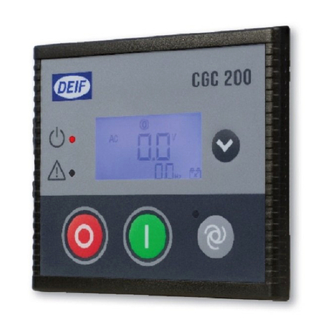
Deif CGC 200 User manual

DEIF A/S · Frisenborgvej 33 · DK-7800 Skive · Tel.: +45 9614 9614 · Fax: +45 9614 9615 · info@deif.com · www.deif.com
OPERATOR'S MANUAL
Compact Genset Controller, CGC 200
● Push-buttons, LEDs and display
● Basic tasks
● Controller parameters
● Monitoring operating data
Document no.: 4189340770A
SW version: 1.xx or later

1. Introduction
1.1. About the Operator's manual..................................................................................................................4
1.1.1. General purpose ...........................................................................................................................4
1.1.2. Intended users...............................................................................................................................4
1.1.3. Revision information .....................................................................................................................4
1.1.4. Software version ...........................................................................................................................4
1.1.5. Other technical documentation......................................................................................................4
1.1.6. Getting technical support...............................................................................................................5
1.2. Warnings, safety and legal information..................................................................................................5
1.2.1. Warnings and notes.......................................................................................................................5
1.2.2. Safety issues ................................................................................................................................5
1.2.3. Factory settings ............................................................................................................................6
1.2.4. Electrostatic discharge awareness ...............................................................................................6
1.2.5. Legal information ..........................................................................................................................6
2. Front panel, push-buttons, LEDs and display
2.1. Front panel.............................................................................................................................................7
2.1.1. Front panel drawing.......................................................................................................................7
2.2. Push-buttons..........................................................................................................................................7
2.2.1. Push-button functions....................................................................................................................7
2.3. LEDs.......................................................................................................................................................8
2.3.1. LED functions................................................................................................................................8
2.4. Display....................................................................................................................................................8
2.4.1. Display functions............................................................................................................................8
2.4.2. Display views ................................................................................................................................8
2.4.3. Alarms............................................................................................................................................9
2.4.4. General icons...............................................................................................................................10
2.4.5. Alarm icons..................................................................................................................................11
2.4.6. Display.........................................................................................................................................11
3. Using the controller
3.1. Genset control mode and status..........................................................................................................12
3.1.1. Genset control mode...................................................................................................................12
3.1.2. Genset status...............................................................................................................................12
3.2. Basic tasks...........................................................................................................................................12
3.2.1. Manual start.................................................................................................................................12
3.2.2. Auto start.....................................................................................................................................12
3.2.3. Viewing operating values.............................................................................................................12
3.2.4. Viewing alarms............................................................................................................................13
3.2.5. Resetting alarms..........................................................................................................................13
3.2.6. Stopping the genset.....................................................................................................................13
3.2.7. Adjusting and testing the display ................................................................................................13
4. Parameters
4.1. Changing parameters...........................................................................................................................14
4.1.1. Warning about changing parameters...........................................................................................14
4.1.2. Parameter list...............................................................................................................................15
4.1.3. Changing parameters using the front panel.................................................................................19
5. Using the Utility Software
5.1. Getting started......................................................................................................................................21
5.1.1. Installing the Utility Software .......................................................................................................21
5.1.2. Starting the Utility Software ........................................................................................................24
5.2. Utility Software overview......................................................................................................................27
5.2.1. Utility Software pages and icons..................................................................................................27
5.2.2. Device page.................................................................................................................................29
5.2.3. Alarms page ................................................................................................................................30
5.2.4. Trending page..............................................................................................................................30
CGC 200 Operator's manual 4189340770
UK
DEIF A/S Page 2 of 43

5.2.5. Parameters page.........................................................................................................................33
5.2.6. Inputs/Outputs page ...................................................................................................................35
5.3. Using the Utility Software.....................................................................................................................35
5.3.1. Changing parameters..................................................................................................................35
5.3.2. Configuring inputs and outputs....................................................................................................36
5.3.3. Reading from the controller.........................................................................................................37
5.3.4. Writing to the controller................................................................................................................38
5.3.5. Firmware upgrade .......................................................................................................................39
6. Glossary
6.1. Abbreviations and terms.......................................................................................................................41
6.1.1. Abbreviations...............................................................................................................................41
6.1.2. Terms...........................................................................................................................................42
6.1.3. Units.............................................................................................................................................43
CGC 200 Operator's manual 4189340770
UK
DEIF A/S Page 3 of 43

1. Introduction
1.1 About the Operator's manual
1.1.1 General purpose
This is the Operator’s manual for DEIF’s Compact Genset Controller, the CGC 200 series. The general pur-
pose is to give the operator important information to be used in the daily operation of the unit.
Please read this manual before working with the CGC 200 controller and the genset to be con-
trolled. Failure to do this could result in damage to the equipment or human injury.
The document includes information about push-buttons, LEDs, display readings and an icon list. Basic tasks
are described, as well as using the utility software to monitor operation.
1.1.2 Intended users
This Operator’s manual is mainly intended for the daily user. Using the information in this document, the oper-
ator will be able to carry out simple day-to-day tasks. The operator will also be able to monitor the system
using the utility software.
1.1.3 Revision information
The letter at the end of the document number on the front page indicates the revision number of this docu-
ment.
The latest version of this document can be downloaded at www.deif.com. If you click on the revision letter to
the right of the document name, the revision history is displayed.
1.1.4 Software version
This document is based on the following software versions:
Software type Software version
CGC 200 firmware CGC 200 SW version 1.xx
Utility software Multi-line 2 Utility Software v.3.x.
1.1.5 Other technical documentation
The CGC 200 documentation consists of the following documents:
● Quick start guide
● Front panel
● Initial start-up
● Parameter setting
● Wiring diagram
● Mounting
● Some technical specifications
● Data sheet
● Description, features, functions and approvals
● Layout and dimensions
● Terminals and wiring diagram
● Technical specifications
CGC 200 Operator's manual 4189340770
UK
Introduction
DEIF A/S Page 4 of 43

● Designer's handbook
● Description of functions and sequences
● Parameters
● Utility software
● Installation and commissioning instructions
● Tools required
● Mounting the controller
● Terminals and wiring diagram
● Parameters
● Sequence for commissioning
● Commissioning using the utility software
● Commissioning using the front panel
● Technical support
● Operator's manual
● Basic operator tasks
● Front panel
● Parameters
● Utility software
● Technical support
Glossaries are included in the Designer's handbook, the Installation and commissioning instructions
and the Operator's manual.
1.1.6 Getting technical support
You can read about service and support options on the DEIF website, www.deif.com. You can also find con-
tact details on the DEIF website.
You have the following options if you need technical support for your controller:
● Technical documentation: All the product technical documentation is available on the DEIF website.
● Training: You can ask for training.
● Support: You can call or email DEIF. DEIF offers 24-hour support. There may also be a local DEIF sub-
sidiary.
● Service: DEIF engineers can help with design, commissioning, operating and optimisation.
1.2 Warnings, safety and legal information
1.2.1 Warnings and notes
A number of warnings and notes are included in this document. These are highlighted, to separate them from
the general text.
Warnings indicate potentially dangerous situations. If the guidelines are not followed, these sit-
uations could result in death, personal injury or damaged equipment.
Notes provide general, helpful information.
1.2.2 Safety issues
Installing and operating the unit may require work with dangerous currents and voltages. The installation must
only be carried out by authorised personnel who understand the risks involved in working with live electrical
equipment.
CGC 200 Operator's manual 4189340770
UK
Introduction
DEIF A/S Page 5 of 43

Hazardous live currents and voltages. Do not touch any terminals, especially the AC measure-
ment inputs. Touching the terminals could lead to injury or death.
DEIF does not recommend using the PC USB as the primary power supply for the CGC 200.
The power drawn on start up exceeds the USB standard and may damage the PC.
1.2.3 Factory settings
The controller is delivered pre-programmed from the factory with a set of factory settings. These are based on
average values and are therefore not necessarily correct for your genset. All controller parameters must be
checked before running the genset.
1.2.4 Electrostatic discharge awareness
Protect the controller terminals from static discharge during installation. You must also protect the terminals if
you need to remove the controller.
These precautions are no longer necessary once the controller is correctly installed and connected, as re-
quired by the designer's wiring diagram.
1.2.5 Legal information
DEIF takes no responsibility for the installation or operation of the genset. Contact the genset company if you
have any doubt about installing or operating the genset.
The controller must not be opened by unauthorised personnel. If opened, the warranty is void.
Disclaimer
DEIF A/S reserves the right to change any of the contents of this document without prior notice.
Trademarks
DEIF, power in control and the DEIF logo are trademarks of DEIF A/S.
Windows is a registered trademark of Microsoft Corporation in the United States and other countries.
All trademarks are the properties of their respective owners.
Copyright
© Copyright DEIF A/S 2012. All rights reserved.
CGC 200 Operator's manual 4189340770
UK
Introduction
DEIF A/S Page 6 of 43

2. Front panel, push-buttons, LEDs and display
2.1 Front panel
2.1.1 Front panel drawing
The drawing below shows the CGC 200 front panel.
2.2 Push-buttons
2.2.1 Push-button functions
The push-buttons on the front panel have the following functions:
Button Description Function
Stop ● Stops the engine and changes the mode to Stop if the genset is running.
● Resets the alarms if there is a shutdown alarm.
● Tests all the LEDs and the full LCD display if pressed for more than three
seconds in Stop mode.
● Changes the mode to Manual, if in Auto mode.
Start ● Starts the engine (Manual mode only).
● Changes the mode to Manual, if in Auto mode.
Auto mode Changes from Manual to Auto mode.
Page down Pages down, to show other operating values.
The push-buttons on the front panel can also be used to change the controller parameters. This is described
later in this manual.
CGC 200 Operator's manual 4189340770
UK
Front panel, push-buttons, LEDs and
display
DEIF A/S Page 7 of 43

2.3 LEDs
2.3.1 LED functions
The display unit has three LEDs. The lighting and status of the LEDs vary according to the situation.
The display LEDs indicate the following:
LED Description Status Situation
Power OK OFF The unit is not powered up.
RED STEADY The power supply is within the limits.
Alarm LED OFF No alarm present.
RED FLASHING Active, non-acknowledged alarm(s) present.
Mode OFF The unit is in manual mode.
RED STEADY The unit is in auto mode.
2.4 Display
2.4.1 Display functions
The display (dimensions 20 mm x 40 mm) shows readings and alarms. Examples, with icons, in English, are
given below.
2.4.2 Display views
You can see the genset's measured values in the views on the CGC 200 LCD display. Press to scroll
through the views.
Example: Genset AC voltage and frequency (Hz)
CGC 200 Operator's manual 4189340770
UK
Front panel, push-buttons, LEDs and
display
DEIF A/S Page 8 of 43

Example: Battery DC voltage and genset running speed (RPM)
Example: Battery DC voltage and total genset running hours
2.4.3 Alarms
If an alarm is activated, it is shown on the screen by the alarm icon. See the examples below.
Example of over-speed alarm
Example of auxiliary alarm
CGC 200 Operator's manual 4189340770
UK
Front panel, push-buttons, LEDs and
display
DEIF A/S Page 9 of 43

2.4.4 General icons
The general icons are listed in the table below.
General icons Description
Auto mode
Stop mode
Manual mode
AC Generator voltage indication
DC Battery voltage indication
rpm Speed unit (revolutions per minute)
kPa Oil pressure unit
VVoltage unit
%Fuel level unit (%)
oCTemperature unit
Hz Frequency unit
HAccumulated running time (hours)
Engine running
CGC 200 Operator's manual 4189340770
UK
Front panel, push-buttons, LEDs and
display
DEIF A/S Page 10 of 43

2.4.5 Alarm icons
The table below lists the CGC 200 display alarms icons, along with their descriptions.
Alarm icons Description
High temperature
Low oil pressure
Over-speed
Under-speed
Emergency stop
Generator over-voltage
Generator under-voltage
Start failure
Stop failure
Battery over- or under-voltage
Auxilliary alarm
Low fuel level
2.4.6 Display
The display is a backlit LCD text display containing lines with characters and icons.
The display light intensity can be adjusted by pressing for more than five seconds.
You can test the LED lamps and display by pressing for more than three seconds.
During operation, the units and icons that are not relevant will not be displayed.
CGC 200 Operator's manual 4189340770
UK
Front panel, push-buttons, LEDs and
display
DEIF A/S Page 11 of 43

3. Using the controller
3.1 Genset control mode and status
3.1.1 Genset control mode
There are three possible genset control modes:
● Manual: The genset is started and stopped by pressing the push-buttons on the front panel.
● Auto: The genset can be started using a remote signal.
● Stop: The genset is stopped. In this mode, alarms can be reset and the display can be tested.
The genset can be on standby in the Auto and Stop modes.
3.1.2 Genset status
There are four possible genset statuses:
● Stopped
● Starting: this can include Crank, Fuel on and Not running
● Running
● Cooling down
See the Designer's handbook for more information about the controller functions and sequences. The De-
signer's handbook also has more information on the genset statuses listed above.
3.2 Basic tasks
3.2.1 Manual start
To start the genset manually:
1. Ensure that the controller is in Manual mode.
● If the controller is in Auto mode, the LED next to will be lit. Press to change to Manual
mode.
2. Press .
● The controller will run the start sequence. If everything is OK, the genset will start.
3.2.2 Auto start
For auto start:
1. Make sure that the controller is in Auto mode. The LED next to will be lit in Auto mode.
● If the controller is not in Auto mode, press .
2. Send the remote start signal to the controller. The controller will run the auto start sequence. If everything
is OK, the genset will start.
3.2.3 Viewing operating values
To view operating values on the front panel, press . The display will show a new set of operating values
each time the button is pressed.
CGC 200 Operator's manual 4189340770
UK
Using the controller
DEIF A/S Page 12 of 43

3.2.4 Viewing alarms
The LED flashes when there is an alarm condition. You can see which alarm is present by looking at
the icons on the display.
3.2.5 Resetting alarms
To reset the alarms if there is a shutdown alarm, press .
3.2.6 Stopping the genset
To stop the genset:
1. Make sure that the genset is in Manual mode.
● If the genset is in Auto mode, press .
2. Press .
3.2.7 Adjusting and testing the display
The display light intensity can be adjusted by pressing for more than five seconds. Keep pressing
until the light level (0 to 7) is right for you. 0 corresponds to the dimmest light, and 7 corresponds to the
brightest light.
You can test the LED lamps and display by pressing for more than three seconds. If the LED lamps are
working correctly, these will all be lit. If the display is working correctly, it should look like the image below.
CGC 200 Operator's manual 4189340770
UK
Using the controller
DEIF A/S Page 13 of 43
4. Parameters
4.1 Changing parameters
4.1.1 Warning about changing parameters
Be very careful about changing the controller parameters. Changing the controller parameters may affect the
genset protections and performance.
The controller parameters are set during the design. These parameters may be adjusted if necessary during
commissioning. Controller parameters should not be changed without first consulting qualified and experi-
enced persons.
For more information about the controller functions and sequences that the parameters are based on, see the
Designer's handbook.
You should make a back-up of the controller before changing parameters.
You should also make a back-up of the controller after changing parameters, to be able to restore the system
in future.
Make sure that the new controller parameters will not damage the genset system.
CGC 200 Operator's manual 4189340770
UK
Parameters
DEIF A/S Page 14 of 43
4.1.2 Parameter list
The parameters used by CGC 200 that can be changed from the controller front panel are listed in the table
below.
Param-
eter
num-
ber
Parameter
name
Range De-
fault
value
Value
chos-
en*
Description
P00 Auto start delay 0 to 3600 s 1 Timer for starting using the Auto start
signal
P01 Auto stop delay 0 to 3600 s 1 Timer for stopping after the Auto start
signal is removed
P02 Start attempts 1 to 10 3 Number of start attempts in one start se-
quence
P03 Start prepare 0 to 300 s 0 Timer for start prepare
P04 Start on time 3 to 60 s 8 Timer for starter ON time during crank-
ing
P05 Start off time 3 to 60 s 10 Timer for starter OFF time before a new
start attempt is made
P06 Initial inhibit de-
lay
1 to 60 s 10 Timer for bypassing frequency and volt-
age shutdown during starting
P07 Idle start 0 to 3600 s 0 Timer for idle speed after starting
P08 GB close delay 3 to 3600 s 10 Timer for generator breaker close after
frequency and voltage OK
P09 Cooldown time 3 to 3600 s 10 Cooling down time
P10 Idle stop 0 to 3600 s 0 Timer for idle speed before stopping
P11 Extended stop 0 to 120 s 20 Timer for extended stop
P12 Stop failure 0 to 120 s 0 Maximum allowable time for stopping
the genset
P13 Number of teeth 10 to 300 118 The number of teeth on flywheel. This is
only used when MPU is selected as run-
ning detection (see P40).
P14 Number of gen.
poles
2 to 32 4 The number of genset poles. This is
used in the frequency calculation.
P15 Hz/V OK delay 0 to 20.0 s 10.0 Voltage and frequency OK delay after
starting of genset
P16 G U > 30 to 360 V 264 Generator over-voltage protection
P17 G U < 30 to 360 V 196 Generator under-voltage protection
P18 G RPM < 0 to 6000
RPM
1200 Generator under-speed protection, if
running detection (see P40) is RPM in-
put only
CGC 200 Operator's manual 4189340770
UK
Parameters
DEIF A/S Page 15 of 43
Param-
eter
num-
ber
Parameter
name
Range De-
fault
value
Value
chos-
en*
Description
P19 G RPM > 0 to 6000
RPM
1710 Generator over-speed protection, if run-
ning detection (see P40) is RPM input
only
P20 G f < 0 to 75.0 Hz 45.0 Generator under-frequency protection
P21 G f > 0 to 75.0 Hz 57.0 Generator over-frequency protection
P22 Running feed-
back timer
0 to 20.0 s 5.0 Maximum allowable time for running de-
tection (see P40)
P23 U > aux. term.1 12.0 to 40.0 V 33.0 High battery supply voltage
P24 U < aux. term.1 4.0 to 30.0 V 8.0 Low battery supply voltage
P25 Relay 01 0 to 6 4 See Table 1: Configurable output func-
tions
P26 Relay 02 0 to 6 1
P27 Relay 03 0 to 6 2
P28 Digital input 1 0 to 10 5 See Table 2: Configurable input func-
tions
P29 Digital input 1
timer
0 to 20.0 s 10.0
P30 Digital input 2 0 to 10 6
P31 Digital input 2
timer
0 to 20.0 s 2.0
P32 Digital input 3 0 to 10 4
P33 Digital input 3
timer
0 to 20.0 s 1.0
P34 Digital input 4 0 to 10 2
P35 Digital input 4
timer
0 to 20.0 s 3.0
P36 Digital input 5 0 to 10 1
P37 Digital input 5
timer
0 to 20.0 s 10.0
P38 Default genset
mode
0 to 2 0 0: Stop mode
1: Manual start
2: Auto start
P39 Display pass-
word
0 to 9999 2000 Prevents unauthorised changes to pa-
rameters using the controller front panel
CGC 200 Operator's manual 4189340770
UK
Parameters
DEIF A/S Page 16 of 43
Param-
eter
num-
ber
Parameter
name
Range De-
fault
value
Value
chos-
en*
Description
P40 Running detect. 0 to 2 2 0: RPM
1: Genset frequency
2: RPM and frequency (running detec-
tion is present when the value required
to remove the starter is met for either
engine speed (see P41) or genset fre-
quency (see P42))
For RPM, P13 and P41 must be de-
fined.
For frequency, P42 must be defined.
P41 Remove starter
RPM
0 to 3000
RPM
360 Minimum engine speed required for re-
moval of the starter and running detec-
tion
P42 Remove starter
Hz
10.0 to 30.0
Hz
14.0 Minimum genset frequency required for
removal of the starter and running de-
tection
*You can fill in the values chosen for your system.
CGC 200 Operator's manual 4189340770
UK
Parameters
DEIF A/S Page 17 of 43
The parameters used by CGC 200 that can only be viewed and changed from the utility software are listed in
the table below.
Param-
eter
number
Parameter name Range De-
fault
value
Value
chos-
en*
Description
43 Calibrate AC voltage 700 to 1300 1000 See the Designer's handbook
for more information
44 Calibrate battery voltage 700 to 1300 1000 See the Designer's handbook
for more information
45 Running hours offset
(9999-19998)
0 to 9999
hours
0 Additional offset for the genset's
running time timer
46 Running hours offset
(0-9999)
0 to 9999
hours
0 Additional offset for the genset's
running time timer
47 Running minutes offset 0 to 59 mi-
nutes
0 Additional offset for the genset's
running time timer
48 Running seconds offset 0 to 59 s 0 Additional offset for the genset's
running time timer
49 Start attempts offset
(9999-19998)
0 to 9999 0 Additional offset for the genset's
start attempts counter
50 Start attempts offset
(0-9999)
0 to 9999 0 Additional offset for the genset's
start attempts counter
*You can fill in the values chosen for your system.
Table 1: Configurable output functions
Configurable output function Value in the controller Config. output*
Not used 0
Common alarm 1
Stop coil 2
Pre-heat 4
Idle speed 3
Close breaker 6
*You can fill in the number of the corresponding relay configured for this function in your system.
CGC 200 Operator's manual 4189340770
UK
Parameters
DEIF A/S Page 18 of 43

Table 2: Configurable input functions
Configurable input function Value in the controller Digital input*
Not used 0
Remote start/stop 6
Low fuel level warning 5
Low oil pressure warning 8
Low oil pressure shutdown 2
High oil temperature warning 7
High oil temperature shutdown 1
High coolant temperature shutdown 9
Auxiliary alarm shutdown (Emergency stop) 4
*You can fill in the number of the corresponding digital input configured for this function in your system.
4.1.3 Changing parameters using the front panel
To change parameters by using the front panel:
1. Press and simultaneously to go into parameter setting mode.
2. The access code screen opens. The four-digit access code prevents unauthorised people from changing
the CGC 200 setup via the front buttons. The factory default code is 2000. To enter the access code:
1. Press to increase the value of the digit where the cursor is blinking. You can use to de-
crease the value.
2. Press to move to the next digit.
3. When the cursor is on the last digit, press to enter the access code. The parameter list now
opens.
3. Press or to get to the parameter you want to change.
4. Press to start editing the parameter.
1. Press to increase the value of the digit where the cursor is blinking. You can use to de-
crease the value.
2. Press to move to the next digit.
3. When the cursor is on the last digit, press to enter the change.
4. After the change is entered, none of the parameter digits will blink. You can now press or
to get to the next parameter you want to change.
5. When you have finished changing parameters, press to exit parameter setting mode.
The table below lists the functions of the push-buttons in parameter setting mode.
CGC 200 Operator's manual 4189340770
UK
Parameters
DEIF A/S Page 19 of 43

Button Description Function
and
OFF and PAGE DOWN together Enter parameter setting mode
AUTO Increase value, or next parameter
ON Decrease value, or previous parameter
PAGE DOWN Next, or Enter
OFF Exit
CGC 200 Operator's manual 4189340770
UK
Parameters
DEIF A/S Page 20 of 43
Other manuals for CGC 200
1
Table of contents
Other Deif Controllers manuals

Deif
Deif CGC 400 Product guide

Deif
Deif AGC-4 User manual

Deif
Deif SGC 120 User manual

Deif
Deif AGC 200 Series User manual

Deif
Deif AGC-4 User manual

Deif
Deif SGC 121 User manual

Deif
Deif SGC 420 User manual

Deif
Deif Multi-line 2 User manual

Deif
Deif GC-1F User manual

Deif
Deif AGC 200 Series Instruction Manual

Deif
Deif DVC 310 Installation and operation manual

Deif
Deif AGC 150 User manual

Deif
Deif AGC 150 User manual

Deif
Deif AGC-4 User manual

Deif
Deif PICUS PPM 300 User manual

Deif
Deif SGC 410 User manual

Deif
Deif Multi-line 2 User manual

Deif
Deif AGC 200 Series User manual

Deif
Deif AGC-4 User manual

Deif
Deif CGC 200 Installation and operation manual