Mesa 7I44 User manual

7I44 MANUAL
8 CHANNEL RS-422 INTERFACE
V1.1

This page intentionally almost blank

iii
Table of Contents
GENERAL . . . . . . . . . . . . . . . . . . . . . . . . . . . . . . . . . . . . . . . . . . . . . . . . . . . . . . . . . . 1
DESCRIPTION . . . . . . . . . . . . . . . . . . . . . . . . . . . . . . . . . . . . . . . . . . . . . . . . . 1
HARDWARE CONFIGURATION . . . . . . . . . . . . . . . . . . . . . . . . . . . . . . . . . . . . . . . . 2
DEFAULT CONFIGURATION . . . . . . . . . . . . . . . . . . . . . . . . . . . . . . . . . . . . . 2
CABLE POWER SELECTION . . . . . . . . . . . . . . . . . . . . . . . . . . . . . . . . . . . . . 2
CONNECTORS . . . . . . . . . . . . . . . . . . . . . . . . . . . . . . . . . . . . . . . . . . . . . . . . . . . . . . 3
CONNECTOR LOCATIONS AND DEFAULT JUMPERS . . . . . . . . . . . . . . . . . 3
CONTROLLER CONNECTOR . . . . . . . . . . . . . . . . . . . . . . . . . . . . . . . . . . . . . 4
AUX 5V POWER . . . . . . . . . . . . . . . . . . . . . . . . . . . . . . . . . . . . . . . . . . . . . . . 4
RJ-45 CONNECTORS . . . . . . . . . . . . . . . . . . . . . . . . . . . . . . . . . . . . . . . . . . . 5
OPERATION
5VPOWER ................................................... 6
RS-485 CAPABLE CHANNELS . . . . . . . . . . . . . . . . . . . . . . . . . . . . . . . . . . . . 6
INTERFACING WITH MESA SERIAL DEVICES . . . . . . . . . . . . . . . . . . . . . . . 6
SPECIFICATIONS . . . . . . . . . . . . . . . . . . . . . . . . . . . . . . . . . . . . . . . . . . . . . . . . . . . 7
DRAWINGS . . . . . . . . . . . . . . . . . . . . . . . . . . . . . . . . . . . . . . . . . . . . . . . . . . . . . . . . 8

7I44 1
GENERAL
DESCRIPTION
The 7I44 is a 8 channel RS-422/RS-485 interface for Mesa s Anything I/O series of
FPGA interface cards.The 7I44 has 8 independent receive and transmit channels. Each
transmit channel has a independent drive enable for bus or 2 wire half duplex systems.
The controller connection is a 50 pin header that matches the pinout of the 4I34M,
4I38, 4I65, 4I68, 5I20, 5I22, 5I23, 7I43 and7I60 Anything I/O cards. SerialI/O connectors
are RJ45 jacks allowing standard CAT5 cables to be used for high speed serial links. The
7I44 also supplies 5V power on the RJ 45 connectors. PTC devices limit maximum 5V
current to 1A .
The RJ45 serial interface pinout used is compatible with all of Mesa’s serially
connected amplifiers and all serially interfaced I/O cards.

7I44 2
HARDWARE CONFIGURATION
GENERAL
Hardwaresetupjumperpositionsassumethatthe7I44cardisorientedinanupright
position, that is, with the 50 pin controller connector is on the left hand side.
DEFAULT CONFIGURATION
JUMPER FUNCTION DEFAULT SETTING
W1 CABLE/AUX 5V POWER TOP = CABLE 5V POWER
.
CABLE POWER/P1/TB2 POWER SELECTION
The 7I44 can get its operating power from the flat FPGA cable or from P1. For
testing and with very low power remote devices, cable power can be used. W1 selects
whether cable power connects to the 7I44s 5V supply. If W1 is in the "TOP" position,
cable power is selected. If W1 is in the "BOTTOM" position, external 5V power must be
supplied via P1/TB2. If 5V power is supplied externally via P1/TB2, W1 must be in the
BOTTOM position or the PC will not start.
Note: Do not connect to 4 pin header connector P1 on REV B or earlier 7I44's
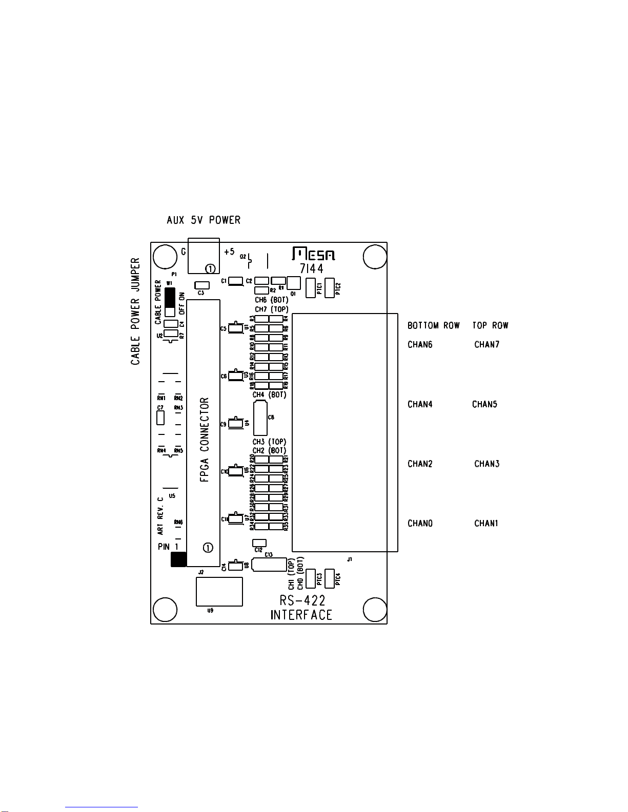
7I44 3
CONNECTORS
CONNECTOR LOCATIONS AND DEFAULT JUMPER POSITIONS

7I44 4
CONNECTORS
CONTROLLER CONNECTOR
50pinheaderconnectorJ1connectstotheanythingI/Ocard/motioncontroller.This
can be a male 50 pin header on the top of the 7I44 card or a female 50 conductor header
on the bottom side of the 7I44 depending on 7I44 model.
PIN FUNCTION DIRECTION PIN FUNCTION DIRECTION
1 RX0 FROM 7I44 25 RX4 FROM 7I44
3 RX1 FROM 7I44 27 RX5 FROM 7I44
5 RX2 FROM 7I44 29 RX6 FROM 7I44
7 RX3 FROM 7I44 31 RX7 FROM 7I44
9 TX0 TO 7I44 33 TX4 TO 7I44
11 /TXEN0 TO 7I44 35 /TXEN4 TO 7I44
13 TX1 TO 7I44 37 TX5 TO 7I44
15 /TXEN1 TO 7I44 39 /TXEN5 TO 7I44
17 TX2 TO 7I44 41 TX6 TO 7I44
19 /TXEN2 TO 7I44 43 /TXEN6 TO 7I44
21 TX3 TO 7I44 45 TX7 TO 7I44
23 /TXEN3 TO 7I44 47 /TXEN7 TO 7I44
49 +5V PWR TO 7I44
Note: all even pins are grounded.
AUX 5V POWER
2 pin pluggable terminal P1 (REV C and above) or screw terminal block TB2 (Rev
B or lower) can be used to supply 5V power to the I/O terminals on the7I44. This is
suggested for applications where the total power drawn by external devices is more than
400 mA. P1/TB2 have the following pinout:
PIN FUNCTION
1 5V
2 GND

7I44 5
CONNECTORS
RJ45 JACK PINOUT
All RJ-45 jacks havethesame pin-out. This pin-out is complementary tothe pin-out
used on all of Mesa’s remote serial devices. When used with Mesa devices a straight
throughCAT6cableisrequired.InadditiontoprovidingfullduplexRS-422communication
the CAT6 cable provides a small amount of 5V power to some remote devices.
PIN FUNCTION DIR CAT6 568B COLOR
1 TX- FROM 7I44 ORANGE/WHITE
2 TX+ FROM 7I44 ORANGE
3 RX- TO 7I44 GREEN/WHITE
4 GND FROM 7I44 BLUE
5 GND FROM 7I44 BLUE/WHITE
6 RX+ TO 7I44 GREEN
7 +5V FROM 7I44 BROWN/WHITE
8 +5V FROM 7I44 BROWN
Note that actual signal functions depend on FPGA configuration.
5V cable power is protected by a PTC device with maximum let through current of
approximately 3Amps. Connectors are protected in pairs with one PTC device used for 2
connectors.
.

7I44 6
OPERATION
5V POWER
The 7I44 requires ~100 mA of 5V power for operation. This power will increase
based onthe number of terminated TXoutputs used, and powerused byexternal devices.
If only lowpower external devices are used the 7I44 can be run entirely from cable
power. (W1 UP) If more than about 400mA of total external power is used. It is suggested
that the 7I44 be powered form an external 5V source (W1 DOWN)
RS-485 CAPABLE CHANNELS
All of the serial channels on the 7I44 have output enables and can be used for RS-
485 half duplex type applications. For 2 wire half duplex type RS-485 interfaces, the RX+
and TX+ lines and the RX- and TX- lines should be tied together at the 7I44.
INTERFACING WITH MESA SERIAL DEVICES
The 7I44 in intended as an interface to MESA’s serial I/O devices that use RS-422
communication and RJ45/CAT5 cable for the serial interface. These devices include the
7I64 Isolated I/O interface, the 8I20 3phase drive, the 7I66 isolated I/O interface, the 7I69
TTL I/O interface, 7I70 isolated input, 7I71 isolatedoutput, and the7I73 pendant interface.
Straight through CAT5 or CAT6 cables canbe used but CAT6 is recommended for
better signal fidelity and lower voltage drop. Make sure you are using straight through
cables. Random cables from routers etc are likely to be crossover cables which will not
work and may even damage the 7I44/remote device.

7I44 7
SPECIFICATIONS
MIN MAX UNITS
5V POWER SUPPLY 4.75 5.25 VDC
5V POWER CONSUMPTION --- 200 mA
(all outputs loaded with 130 ohm terminations)
(no serial 5V load)
5V CURRENT TO EACH I/O CONNECTOR --- 640 mA
MAXIMUM DATA RATE --- 10 MBIT/S
RS-422 INPUT COMMON MODE RANGE -7 +12 Volts
RS-422 TERMINATION RESISTANCE 118 122 Ohm
RS-422 OUTPUT LOW
C
.8 Volts
(24 mA sink current)
RS-422 OUTPUT HIGH VCC-2.5
C
Volts
(24 mA source current)
OPERATING TEMP. 0 +70 oC
OPERATING TEMP. (-I version) -40 +85 oC
OPERATION HUMIDITY 0 95% NON-COND
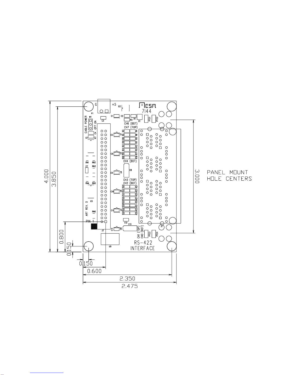
7I44 8
DRAWINGS
Table of contents
Other Mesa Recording Equipment manuals


