15
GP4100 Series Quick Guide
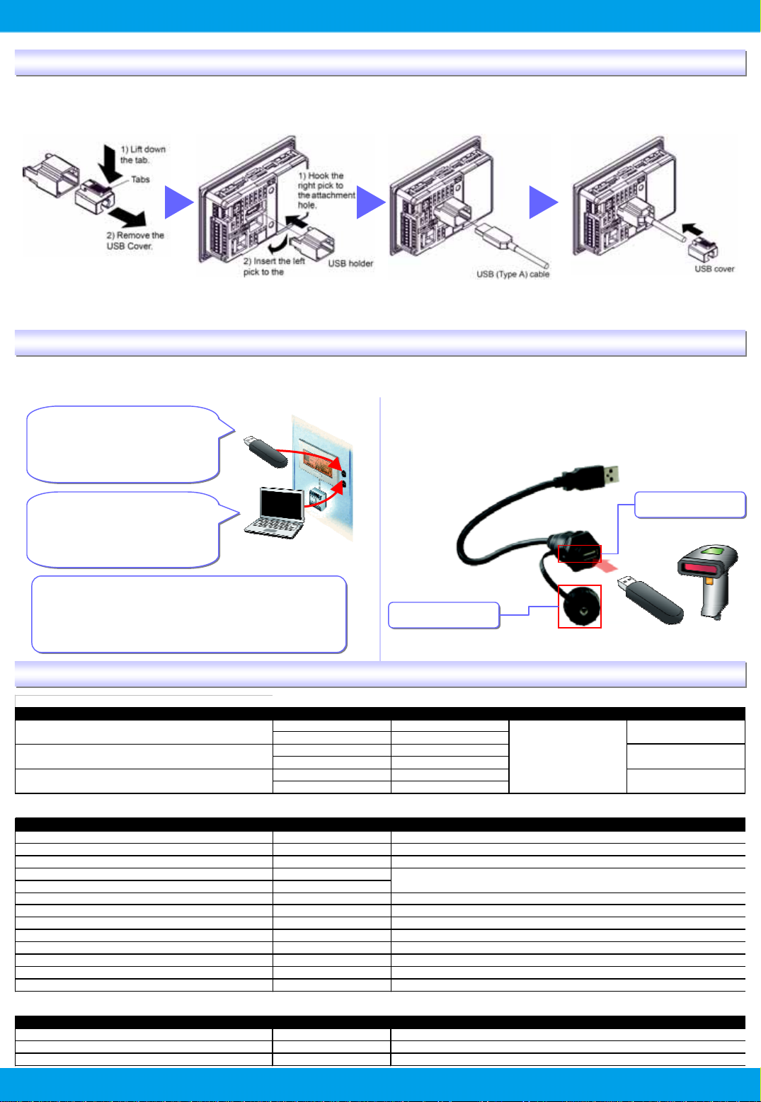
Precaution for USB Cable Clamp (sold separately)
Two types of USB Cable Clamp: for Type A and for mini B.
This clamp is used to prevent a USB cable connected to USB Interface of a GP unit from being unplugged due to vibration or
other causes.
- When a USB Cable Clamp for Type A is used, remove a
USB cover from a USB holder prior to the installation.
Precaution for USB Front Cable (sold separately)
USB Front Cable allows for the use of USB interface without opening an operation panel.
- Only if the waterproof cap is attached to this cable, IP65f is
applied only to the front side.
- Fasten the waterproof cap tightly.
[CA5-USBEXT-01]
GP4100 Series Main Units and Accessories
USB Flash Drive (USB Type A)
- Screen Transfer
- Ladder Transfer
(Supporting only PLC of
Toshiba Machine)
USB Flash Drive (USB Type A)
- Screen Transfer
- Ladder Transfer
(Supporting only PLC of
Toshiba Machine)
PC (USB mini B)
- Screen Transfer
- Ladder Transfer
(Pass-through)
PC (USB mini B)
- Screen Transfer
- Ladder Transfer
(Pass-through)
Easy data reading by easy settings of connecting a USB
code reader to a USB port (Type A).
* When a USB code reader is used, the power should be supplied via a self-
powered hub.
Easy data reading by easy settings of connecting a USB
code reader to a USB port (Type A).
* When a USB code reader is used, the power should be supplied via a self-
powered hub.
USB Port
USB Port
Waterproof Cap
Waterproof Cap
Code Reader
USB Flash Drive
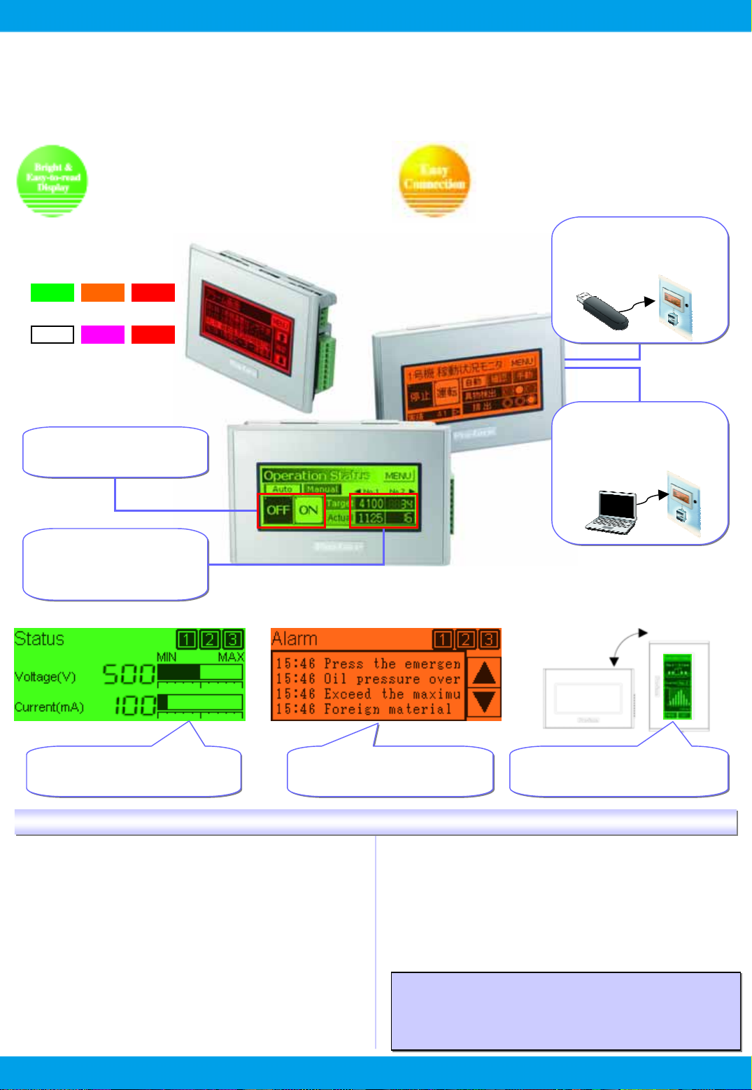
■Units
ProductName Model No. Backlight DisplayType Serial (COM1)
GP-4105G GP4105G1D Green/Orange/Red
GP-4105W GP4105W1D White/Pink/Red
GP-4106G GP4106G1D Green/Orange/Red
GP-4106W GP4106W1D White/Pink/Red
GP-4107G GP4106G1D Green/Orange/Red
GP-4107W GP4106W1D White/Pink/Red
■Optional Products
ProductName Model No.
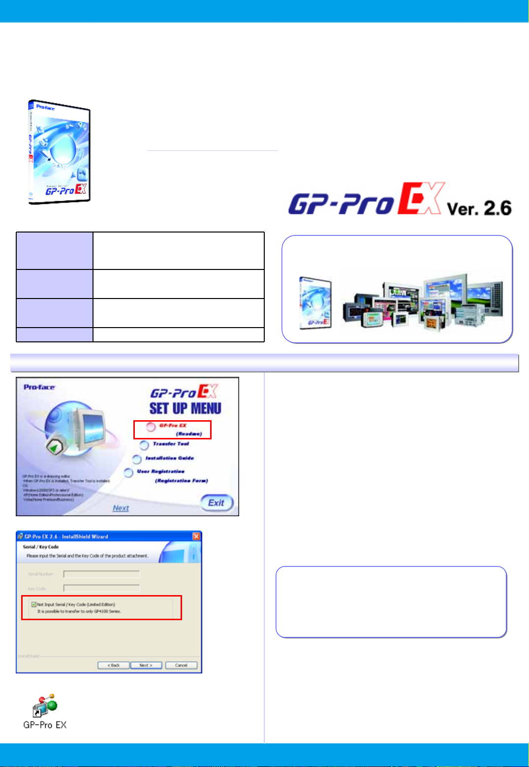
GP-Pro EX EX-ED-V26
USB Transfer Cable (USB A/mini-B) (1.8 m) ZC9USCBMB1
Mitsubishi PLC Q-Series CPU I/F Cable (3 m) ZC9CBQ31
Mitsubishi PLC FX-Series CPU I/FCable (5 m) ZC9CBFX51
Mitsubishi PLC FX-Series CPU I/FCable (1 m) ZC9CBFX11
Mitsubishi PLC A-Series Cable (5 m) ZC9CBA51
Panasonic ElectonicWorks PLC Series CPU Cable (2m) ZC9CBFP21
USB Panel-mount Extension Cable (USB mini-B 1m) ZC9USEXMB1
USBPanel-mount Extension Cable (USBType A1m) CA5-USBEXT-01
USB-Serial (RS-232C) Conversion Cable (0.5m) CA6-USB232-01
3.4-inch Screen Protection Sheet ZC9DS31
USB Clamp TypeA(1 Port) ZC9USCL1
USBClamp Type mini-B (1port) ZC9USCLMB1
■Maintenance Items *Please purchase when the product is damage or lost.
ProductName Model No.
3.4-inch Installation Fastener ZC9AF31
3.4-inch Installation Gasket ZC9WG31
3.4-inch COMI/FConnector ZC9CMC1
Description
3.4" STN
Monochrome LED
RS-232C
RS-422/485
RS-485 (isolation)
Cable for transferring screen data from a PC (Type-A) to the GP (USBmini-B)
Screen-creation software (Ver.2.6 or later required to use GP4100 series)
Connector for Serial I/F ( 1 piece)
USB(Type A) Cable clamp for1 portproducts toprevent disconnection (5pcs/set)
USB(mini-B)Cable clamp for 1 portproducts to preventdisconnection (5 pcs/set)
Description
Used to install the GP intoa solid panel (2 pcs/set)
Connects the GPdirectly to the CPU programming port on the Mitsubishi Electric PLCA/QnA series
Connects the GP directlyto the CPU programming porton the Mitsubishi ElectricPLC Qseries
Connect the GP directly to the CPU programming port on the Mitsubishi Electric Mitsubishi PLC FX-Series PLC FX series
Connects the GP directly to the CPU port on the Panasonic Electric Works PLC FP series
Provides dust and moisture resistance when GPis installed into a solid panel (1 piece)
Extension cable attaching to the USB(mini-B)porton the frontside ofthe operation panel
Extension cable attaching to the USB (Type-A) port on the front side of the operation panel
Cable for converting a GPunit’s USB interface (Type-A) into a serial interface (RS-232C)
Disposable,dirt-resistantsheetfor theGPunit’s screen (5 sheets/set)