Messana mZone 8 Owner's manual

submittal
messana zone
1
November 2018
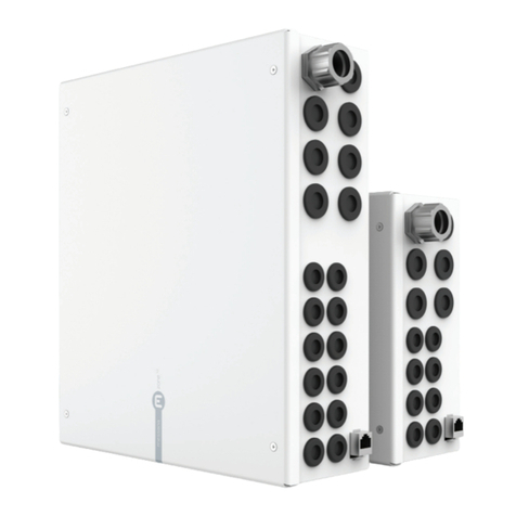
mZone is a fully programmable zone controller available in two different sizes: 8 and 12 zones. It is assembled
with industrial grade components for commercial and residential high-end applications. It connects with mBox via
Ethernet or, alternatively, via serial bus (Rintegrates with the Messana climate control platform
developed with more then 20 years of experience in radiant cooling and heating technology.
Job_________________________ Designer_____________________ Contact_________________________
W1
W2
D
H
W1
W2
D
H
Features Controlled by mBox; connects with mSense; PID temperature control; thermal actuator staggered
powered by Emerson Climate I/O controller.
Size and weight 1size mZone 8
W1:
W2: 8
D:
H:
weight
size mZone 12
W1:
W2:
D:
H:
weight
Casing Mounting type Fixed mounting brackets
Protection grade
Color and finish Arctic white metal enclosure
Environmental requirements Operating ambient temperature
<90%, non condensing

2
November 2018
mZone 8 mZone 12
Inputs 2Analog Inputs (AI) 3
Temperature probes, pressure sensors, flow meters, feedback
Resolution 10-bit A/D converter
NTC 10k 2 2
Auxiliary programmable AI 1 1
Additional 2 programmable AI 3 7
Digital Inputs (DI) 4
Presence or window sensors, H/C changeover, alarms, On/Off
Auxiliary dry contact DI - 1
Additional 2 dry contact DI 11 15
Outputs2 Digital Outputs (DO) 5
Thermal actuators, zone valves, pumps, actuators, activations
8 12
6
7 - 2
110/220VAC 50-60Hz wet contacts for pumps 8 1 10 1
Analog Outputs (AO) 9
Mixing valves, servo motors, actuators, fan-coils
Resolution/Accuracy
2-10V with 24VDC power supply for mix-valve 1 1
– 1
Additional 2 programmable AO 3 (AO2-AO4) 4 (AO3-AO6)
Zone Bus RS485 master with shield and 24VDC sensor power supply up to 8 mSense up to 12 mSense
Communication With Messana mBox module Ethernetor RS485 11
With mSense room sensors RS485 Zone Bus
Power Supply 85 W (4 120 W
Notes 1. Size, weights and technical characteristics may vary without prior notice.
2. There are two different types of I/O connectors: the standard I/Os rail-mounted terminal blocks with Push-in
CAGE CLAMP® (with exception of the power relays mZone8DO8 and mZone12
need to be wired directly on the controller.
3. Analog Inputs can be programmed as: NTC or PTC, 0-20mA, 4-20mA, 0-10V, 0-1V or 0-5V, Digital Input.
4. Digital Inputs are opto-insulated and are dry contacts.
5. Digital Outputs mZone8DO1-DO8 and mZone12
DO8 and mZone12DO13-DO15
are used to control the 24VDC coils of the miniature power relays labeled mZone8DO13-
6.
7.
Can be reconfigured as 24VDC or 110/220VAC wet contacts.
8. Relays socket pre-wired as 110/220VAC wet contact. Voltage depends on the mZone AC power and the main fuse
.Require Finder 44.52.9.024 miniature industrial relay (not
. Can be reconfigured as 24VDC wet contact or dry contact.
9. Analog Outputs are opto-insulated and can be programmed as: 0-10V, 2-10V or 4-20mA.
10.
11. If connected to mBox via serial bus RS485, remote access to the device is not supported.
Technical specifications1

3
November 2018
10.75 (274 mm)
8.5 (214 mm)
10 (254 mm)
8 (206 mm)
9.75 (250 mm)
10.5 (267 mm)
Finder
Relay
44.52.9.024
(supplied
by others)
Fin
der
Rela
y
44.5
2
.
9
.
02
4
(
supplied
by others
)
2
61
4 5
3
DO1 DO2 DO3 DO4
ZONE THERMAL ACTUATORS (24VDC)
DO6 DO7 DO8DO5 SHD 0V 24V D+ D– 0V 24V Y SUPPLY RETURNDI1 24V0V
ZONE BUS
SYNC W/
DO8 (PWR)AO1 MIX AI NTC DI AUX 24 VDC
GND
DO8 (PWR)
NL
Relay HoldersI/O contacts
mZone 8 components and 2D footprint
Components Legend
1Ethernet connection
2
3
4DIN rail-mounted terminal blocks with Push-in CAGE CLAMP® I/O contacts
5DIN rail-mounted relay holders and power relays
6

4
November 2018
10.75 (274 mm)
8.5 (214 mm)
14 (356 mm)
12 (305 mm)
9.75 (250 mm)
10.5 (267 mm)
GND
Finder
Relay
44.52.9.024
(supplied
by others)
Finder
Relay
44.52.9.024
(supplied
by others)
Finder
Relay
44.52.9.024
(supplied
by others)
Finde
r
Rela
y
44.5
2
.
9
.
02
4
(
supplied
by others
)
F
inde
r
Rela
y
44.5
2
.
9
.
02
4
(
supplied
by others
)
F
inde
r
Rela
y
44.5
2
.
9
.
02
4
(
supplied
by others
)
2
61
4 5
3
DO1 DO2 DO3 DO4
ZONE THERMAL ACTUATORS (24VDC)
DO6 DO7DO5 DO9 D10DO8 DO12DO11 SHD 0V 24V D+ D– 0V 24V Y SUPPLY RETURNDI1 24V0V
ZONE BUS AO1 MIX AI NTC DI AUX 24 VDC
0V 24V
AO2 AUX
DO15 (PWR)
NL
DO14
DRY CONTACT
DO13
DRY CONTACT
Relay HoldersI/O contacts
mZone 12 components and 2D footprint
Legend
1Ethernet connection
2
3
4DIN rail-mounted terminal blocks with Push-in CAGE CLAMP® I/O contacts
5DIN rail-mounted relay holders and power relays
6

5
November 2018
zone 2 zone 3 zone 4 zone 5zone 1
zone 1
zone 1
zone 6 zone 7 zone 8 zone 12
DO1 DO2 DO3 DO4
ZONE THERMAL ACTUATORS (24 VDC)
DO5 DO6 DO7 DO8
DO9 DO10 DO11 DO12
DO1 DO2 DO3 DO4
ZONE THERMAL ACTUATORS (24 VDC)
DO5 DO6 DO7 DO8
DO9 DO10 DO11 DO12
mZone 8
mZone 12
max 3
actuators
SH
D0V 24V D+ D–
ZONE BUS
mZone
max 300ft
n 12
max 300ft
n 12
max 300ft
m < n
mSense
ID 1
mSense
ID 2
mSense
ID m
Termination ON
mSense
ID 1
mSense
ID n
Termination ON
mSense
ID m+1
mSense
ID m+2
mSense
ID n
Termination ON
Each digital outputs is a 24VDC normally open contact with max
5Amps. It is possible to connect up to 3 actuators to each Digital
Output with a maximum of 10 actuators for mZone 8 and 17 actuators
for mZone 12.
The maximum number of thermal actuators supported by one mZone
programmed in the mBox unit that controls the mZone.
for each digital output and do not drawn more then 5 Amps for each
digital output.
DO8 mZone 8 digital output DO8 can be used either for the actuation of
also be rewired as a dry contact or 24VDC contact.
ZONE THERMAL ACTUATORS (24VDC) (mZone8DO1-DO8 and mZone12DO1-DO12)
m
actuators or zone valves.
ZONE BUS (SHD, 0V, 24V, D+, D-)
Z
SHD is dedicated to the connection of the serial communication cable shield (
against induced noise. If the serial cable has is a foil shield, then use the shield drain wire.
Without SHD connection, reliability of the protocol can be significantly degraded. Always connect the shield drain
wire to the mZone SHD terminal and make sure the continuity is maintained on each mSense split connection by
twisting together the shield drain wires of the two shielded cables.
0V and 24V terminals are used to supply 24VDC power to the mSense sensors attached on the BUS. Up to 12 sensors
D+ and D-
The mZone acts as a master and the mSense sensors are slaves. To achieve bi-directional communications the
BUS is shared between transmitting and receiving. Polarity between the signals D+ and D-, must be respected.
The last sensor on the bus must be terminated by setting the dip-switch ID#9 to ON.
The mZone module can also be installed in the middle of the bus with two different terminated branches.
Inputs / Outputs contacts

6
November 2018
0V 24V Y
AO1 MIX
BK RD WH OG
Belimo actuator
models
LRB24-SR-T
ARB24-SR-T
SUPPLY RETURN
AI NTC
S R
AO2 AUX
0V Y
0-10V
Analog
Device
is typically used to control a motorized proportional mix
valve to adjust the radiant fluid temperature.
0V, 24V are the terminals to supply power to the valve actuator.
Y
Ycan be program as a 0-10V or 2-10V analog output. AO MIX default value is 2-10V.
Messana suggests the use of the Belimo B3 series 3-Way mixing valves with 2-10V proportional control
actuators: LRB24-SR-TARB24-SR-T
0V, Y
Ycan be program as a 0-10V or 2-10V analog output. AO AUX default value is 0-10V..
AO1 MIX (0V, 24V, Y) and mZone12AO2 AUX
0-10V or 2-10V programmable opto-insulated analog outputs for controlling motorized mixing valves, servo motors, actuators, fan-coils, and
other analog devices. Can also be reprogrammed as 4-20mA.
Inputs / Outputs contacts
AI NTC (SUPPLY / RETURN)
A
AI NTC are dedicated to NTC probes to measure supply and return temperatures of the radiant fluid at the
manifold at the manifold.
SSUPPLY terminals are used for supply fluid NTC temperature probe.
RRETURN terminals are used for return fluid NTC temperature probe.
The SUPPLY thermistors must be installed after the circulator pump.
Analog Inputs can be reprogrammed as PTC, 0-20mA, 4-20mA, 0-10V, 0-1V or 0-5V or digital inputs.
Do not use PT1000 temperature probes. Use only 3435 K 10 kOhms NTC thermistors.
Notes
1. D
2. Refer to “Relay holders and power relays” in this document for more details.

7
November 2018
Inputs / Outputs contacts
DI AUX
DI1
GND
110/220VAC
50/60Hz
Fuse holder
switch
N
L
NO
External
Device
NO
DI1 is a dry contact digital input for external devices (alarm system, fire alarm, window sensor, presence sensor,
force the device ON and OFF.
mZone 8 do not offer any digital input pre-wired on the terminal blocks on the DIN bar. Additional 11 Digital
on the push-in connectors located on the controller.
mZone 12 offers one digital input, DI1, pre-wired on the terminal blocks on the DIN bar. Additional 15 Digital
on the push-in connectors located on the controller.
DI1 AUX (mZone 12 only)
D
contact. In case of event, an external contact is closed and acknowledged by the DI.
N L GND
The fuse holder and disconnect switch can also be used as a fused switch to shut off power to the device by
safely extracting the fuse holder.
Both mZone 8 and mZone 12 are supplied with a 4A fuse
1 Amp is absorbed by the mZone itself and the remaining 3 Amps are available for the power relays
Use ceramic .
N/L/GND Fuse holder and disconnect switch
a fuse circuit protection.
Power contacts

8
November 2018
Finder
Relay
44.52.9.024
(supplied
by others)
DO8 (PWR)
NL
P2 Pump
110V/60Hz
14 24
N
L
12 22
Device
being
controlled
AC power
P1 Pump
110V/60Hz
N
L
DO14
DRY CONTACT
DO13
DRY CONTACT
DO15 (PWR)
NL
Finder
Relay
44.52.9.024
(supplied
by others)
Finder
Relay
44.52.9.024
(supplied
by others)
Finder
Relay
44.52.9.024
(supplied
by others)
14 14
11 11
14 24
12 12
Notes
1. D
2. Refer to “Relay holders and power relays” in the user manual for more details.
The DO13-DO15 of the Emerson I/O controller are 24VDC wet normally open contacts connected to the coil
terminals of three relays holders to provide three contacts that can be singularly wired as dry or wet contacts.
DO13 and DO14 (DRY CONTACTS) are pre-wired as dry contacts.
Use the 11 as common and 14 as normally open (or 12
Double pole dry contact relay 2
If a double pole relay is required, use COM 21 as common and NO 24 as normally open (or NC 22 as normally
activated at the same time by DO13 or DO14 powering the common coil.
DO15 (PWR) is used to control
using 14 24 12 22
110VAC or 220VAC, depending on the mZone AC power, and
is protected by the same fuse of the mZone 8.
Any high voltage supply
and will be protected by the same fuse. The mZone is supplied with a 4A fuse. 1 Amp is absorbed by
Amps are required, the main fuse must be upgraded accordingly. Power relay is rated 250VAC/6A (max
The DO8 of the Emerson I/O controller is a 24 VDC wet contact that is wired in parallel as ZONE THERMAL
The mZone 8 Digital Output DO8 can be used:
• to control the thermal actuator or zone valve of the zone number 8
or, if the number of zones to control are less then 8,
•
DO8 (PWR) is used to
using 14 24 12 22
110VAC or 220VAC, depending on the mZone AC power, and
is protected by the same fuse of the mZone 8.
Any high voltage and
will be protected by the same fuse. The mZone is supplied with a 4A fuse. 1 Amp is absorbed by the mZone
itself and the remaining 3 Amps are available for the power relay. If more then 3 Amps are required, the main
If more then 7 zones are need, use mZone 12.
DO8 (PWR) (mZone 8 only)
Reconfigurable digital output 1with power relays 2.
DO13-DO14 (DRY CONTACTS), DO15 (PWR) (mZone 12 only)
Reconfigurable digital outputs1 with power relays 2.
Inputs / Output power relays

9
November 2018
A2
22
21
24
A1
12
11
14
COM
NO
COIL
NC
COM
NO
COIL
NC
0V 24V
DO
Relay holder pinout
Relay pinout diagram
A2
22
21
24 14
11
12
A1
Model: Finder 44.52.9.024
Coil voltage: 24VDC
Rated voltage/max: 250/400 VAC
Rated current/max: 6A/10A
Finder mini relays model
44.52.9.024 are not
included in the mZone.
Relays can be purchased
separately.
Notes
1.
Relay holders and miniature power relays
External miniature power relays for mZone8DO8 and mZone12DO13-DO15 digital outputs1.
model 44.52.9.024,
Each miniature power relay features two separate poles (“1” left side and “2” right side, top
Each pole come with:
•
• one contact
The two poles are electrically insulated and can be used as a double-pole switch.
Miniature relay Installation
holding band.
Use only Finder mini relay model 44.52.9.024.

10
November 2018
Relay pinout diagram
pole 1
pole 2
A2
22
21
24 14
11
12
A1
DO
DRY CONTACT
Finder
Relay
44.52.9.024
(supplied
by others)
N
L
24V
0V
DO
DRY CONTACT
Finder
Relay
44.52.9.024
(supplied
by others)
110/220VAC
device
NL
Two different voltage devices Line and neutral interruption
Double-pole dry contact relay
The Finder relay features two columns of terminals, COM 11, NC 12, NO 14COM 21, NC 22, NO 24
The two poles are electrically insulated and activated by the same digital output.
Examples of usage:

11
November 2018
Finder
Relay
44.52.9.024
(supplied
by others)
DO1 DO2 DO3 DO4 DO5 DO6 DO7 DO8 DO9 DO10 DO11 DO12
ZONE THERMAL ACTUATORS (24 VDC) ZONE BUS
SHD
AO1 MIX AI NTCAO2 AUX DI AUX
0V 24V D+
D– 0V 24V Y SUPPLY RETURN 0V Y DI1
DO13
DRY CONTACT
DO14
DRY CONTACT
DO15 (PWR)
NL
110/220VAC
50/60Hz
2414
24VDC
device
A2
22
21
24
A1
12
11
14
COM
NO
COIL
NC
COM
NO
COIL
NC
0V 24V
DO
Relay holder pinout
Relay pinout diagram
A2
22
21
24 14
11
12
A1
11 21
holder/s.
To control a 24VDC device use the terminals:
14 24 or 12 22
for a normally open contact with 24VDC for a normally closed contact with 24VDC
2414
11 21
22 2212 12
2414
11 21
Notes
1. Max 8W for all 24VDC wet contacts supplied by the mZone AC/DC power supply. For more then 8W, use an additional DC power supply.
To use these contacts, insert a Finder mini relay model 44.52.9.024
24VDC wet contacts 1
(
1
holders as dry contacts. To use these two contacts, a miniature power relay is required (Finder relay model 44.52.9.024,
1 following the schematic below.
Before proceeding disconnect power.
When completed, mark off the “DRY CONTACT” text on the label to avoid future errors.

12
November 2018
Finder
Relay
44.52.9.024
(supplied
by others)
DO1 DO2 DO3 DO4 DO5 DO6 DO7 DO8 DO9 DO10 DO11 DO12
ZONE THERMAL ACTUATORS (24 VDC) ZONE BUS
SHD
AO1 MIX
AI NTCAO2 AUX DI AUX
0V 24V D+ D– 0V 24V Y SUPP
LY RETURN 0V Y DI1
DO13
DRY CONTACT
DO14
DRY CONTACT
DO15 (PWR)
NL
11 21 11 21
14 1424 24
12 1222 22
2414
110/220VAC
device
NL
A2
22
21
24
A1
12
11
14
COM
NO
COIL
NC
COM
NO
COIL
NC
0V 24V
DO
Relay holder pinout
Relay pinout diagram
A2
22
21
24 14
11
12
A1
mZone AC power
110/220VAC
50/60Hz
Add. AC power
110/220VAC
50/60Hz
Notes
1. T
In this case the controlled device will be under the same fuse of the mZone. Fuse might be upgraded based on the controlled device load.
To use these contacts, insert a Finder mini relay model 44.52.9.024
wet contacts
holders as dry contacts. To use these two contacts, a miniature relay is required (Finder relay model 44.52.9.024, not
following
the instructions below.
Before proceeding disconnect power.
When completed, mark off the “DRY CONTACT” text on the label to avoid future errors.
High voltage (110/220VAC) wet contacts
(
Connect an additional AC power circuit to the COM 11 21 (L 1.
And additional AC power with a dedicated circuit breaker must be added.
To control a 110/220VAC 1 device use the terminals:
14 24 or 12 22
for a normally open contact for a normally closed contact.

13
November 2018
Finder
Relay
44.52.9.024
(supplied
by others)
DO1 DO2 DO3 DO4 DO5 DO6 DO7 DO8 DO9 DO10 DO11 DO12
ZONE THERMAL ACTUATORS (24 VDC) ZONE BUS
SHD
AO1 MIX
AI NTCAO2 AUX DI AUX
0V 24V D+ D– 0V 24V Y SUPP
LY RETURN 0V Y DI1
DO13
DRY CONTACT
DO14
DRY CONTACT
DO15 (PWR)
NL
14
22
24
11
dry contact
relay
DO
14
11
Device
being
controlled
AC power
A2
22
21
24
A1
12
11
14
COM
NO
COIL
NC
COM
NO
COIL
NC
0V 24V
DO
Relay holder pinout
Relay pinout diagram
A2
22
21
24 14
11
12
A1
110/220VAC
50/60Hz
12
21
21
Notes
1. 1
11 21 (110/220VAC 1
Cover the exposed neutral (N) and line (L) wires with twist-on connectors and tape over the wire nut for extra assurance.
Use the COM 11 as common and NO 14 as normally open or NC 12 as normally closed dry contact. Alternatively, or in addition, use the COM 21
as common and NO 24 as normally open or NC 22 as normally closed dry contact.
The two dry contacts ( 11 - 14 / 12 and 21 - 24 / 22
To activate these contacts, insert a Finder mini relay model 44.52.9.024
1 wet contacts to
dry contacts
110/220VAC 1 wet contacts dedicated to directly activate a circulator pump or other high voltage devices. The
circulator pump connected to the wet contacts NO 14will be turned on and off by the relay based
In case the circulator pump or another device need to be controlled with an on/off potential-free contact or a 24VDC
Follow the instructions below to rewire the two wet 110/220VAC 1 contacts into dry contacts.
Before proceeding disconnect power.
When completed, mark off the “PWR N |L” text on the label to avoid future errors.
Dry contacts
(

14
November 2018
Finder
Relay
44.52.9.024
(supplied
by others)
DO1 DO2 DO3 DO4 DO5 DO6 DO7 DO8 DO9 DO10 DO11 DO12
ZONE THERMAL ACTUATORS (24 VDC) ZONE BUS
SHD
AO1 MIX AI NTCAO2 AUX DI AUX
0V 24V D+
D– 0V 24V Y SUPPLY RETURN 0V Y DI1
DO13
DRY CONTACT
DO14
DRY CONTACT
DO15 (PWR)
NL
2414
24VDC
device
A2
22
21
24
A1
12
11
14
COM
NO
COIL
NC
COM
NO
COIL
NC
0V 24V
DO
Relay holder pinout
Relay pinout diagram
A2
22
21
24 14
11
12
A1
24VDC wet contacts
(24VDC is supplied from the mBox AC/DC power supply2
110/220VAC
50/60Hz
24
22
14
12
2111
Notes
1. 110V
2. Max 8W for all 24VDC wet contacts supplied by the mZone AC/DC power supply. For more then 8W, use an additional DC power supply.
To use these contacts, insert a Finder mini relay model 44.52.9.024
1 wet contacts to
24VDC wet contacts
110/220VAC 1 wet contacts dedicated to directly activate a circulator pump or other high voltage devices. The
circulator pump connected to the wet contacts NO 14will be turned on and off by the relay based
Follow the instructions below to rewire the two wet 110/220VAC 1 contacts into 24VDC wet contacts 2.
Before proceeding disconnect power.
When completed, mark off the “DRY CONTACT” text on the label to avoid future errors.
11 21
11 21
DO15 relay holder/s.
To control a 24VDC device, use the following terminals:
NO 14 24 or NC 12 22
for 24VDC normally open contacts 2 for 24VDC normally closed contacts 2

110V/60Hz
15
November 2018
Finder
Relay
44.52.9.024
(supplied
by others)
DO1 DO2 DO3 DO4 DO5 DO6 DO7 DO8
ZONE THERMAL ACTUATORS (24 VDC) ZONE BUS
SHD
AO1 MIX AI NTC
0V 24V D+ D- 0V 24V Y SUPPLY RETURN
DO8 (PWR)
NL
MV1
S R
zone
7
zone
1
zone
2
zone
3
zone
4
zone
5
zone
6
P1 Pump
110V/60Hz
Electrical drawing
R
S
C/H WR C/H WS
MV1P1
Manifold
To Radiant Panels
zone 8
mZone 8
Mechanical drawing
mSense
ID 1
mSense
ID 7
Termination ON
mZone 8 sample application drawing
Below is a sample application drawing for this product. This application may include other Messana products that
are required for installation. More sample applications can be found at radiantcooling.com.
DO8
DO8

16
November 2018
R
S
C/H WR C/H WS
MV1P1
Manifold
To Radiant Panels
zone 12
mZone 12
Up to 12 zones
Mechanical drawing
Finder
Relay
44.52.9.024
(supplied
by others)
DO1 DO2 DO3 DO4 DO5 DO6 DO7 DO8 DO9 DO10 DO11 DO12
ZONE THERMAL ACTUATORS (24 VDC) ZONE BUS
SHD
AO1 MIX AI NTCAO2 AUX DI AUX
0V 24V D+ D– 0V 24V Y SUPPLY RETURN 0V Y DI1
DO13
DRY CONTACT
DO14
DRY CONTACT
DO15 (PWR)
NL
MV1 P1 Pump
110/220V
S R
zone
1
zone
7
zone
8
zone
9
zone
10
zone
11
zone
12
zone
6
zone
5
zone
4
zone
3
zone
2
110/220Vac
50/60Hz
Electrical drawing
mSense
ID 1
mSense
ID 12
mZone 12 sample application drawing
Below is a sample application drawing for this product. This application may include other Messana products that
are required for installation. More sample applications can be found at radiantcooling.com.

Messana Radiant Cooling - 4105 Soquel Dr, Suite B - Soquel, CA 95073 - USA
November 2018
the terms of the Limited Warranty in effect at the time of such Product sale and acknowledges that it has read and understands the same.
The Limited Warranty to the Purchaser on the Products sold hereunder is a manufacturer’s pass-through warranty which the Purchaser is
authorized to pass through to its customers. Under the Limited Warranty, each Product is warranted against defects in workmanship and materials
if the Product is installed and used in compliance with Messana’s instructions, ordinary wear and tear is expected.
be the sole remedy available from Messana.
or use of the product, or from defects in workmanship or materials, including any liability for fundamental breach of contract.
The pass-through Limited Warranty applies only to those defective Products during the Warranty Period. This Limited Warranty does not cover
the cost of the parts or labor to remove or transport the defective Product, or to reinstall the repaired or replacement Product, all such costs and
expenses being subject to Purchaser’s agreement and warranty with its customers.
Any representations or warranties about the Products made by Purchaser to its customers which are different from or in excess of the Messana
Limited Warranty are the Purchaser’s sole responsibility and obligation. Purchaser shall indemnify and hold Messana harmless from and against
any and all claims, liabilities and damages of any kind or nature which arise out of or are related to any such representations or warranties by
Purchaser to its customers.
The pass-through Limited Warranty does not apply if the returned Product has been damaged by negligence by persons other than Messana,
accident, fire, Act of God, abuse or misuse; or has been damaged by modifications, alterations or attachments made subsequent to purchase
which have not been authorized by Messana; or if the Product was not installed in compliance with Messana’s instructions and/or the local codes
and ordinances; or if due to defective installation of the Product; or if the Product was not used in compliance with Messana’s instructions.
LIMITATION OF LIABILITY
THIS WARRANTY IS IN LIEU OF ALL OTHER WARRANTIES, EXPRESS OR IMPLIED, WHICH THE GOVERNING LAW ALLOWS PARTIES TO
CONTRACTUALLYEXCLUDE,INCLUDING,WITHOUTLIMITATION, IMPLIED WARRANTIESOF MERCHANTABILITY AND FITNESSFOR APARTICULAR
PURPOSE, DURABILITY OR DESCRIPTION OF THE PRODUCT, ITS NON INFRINGEMENT OF ANY RELEVANT PATENTS OR TRADEMARKS, AND ITS
COMPLIANCE WITH OR NON VIOLATION OF ANY APPLICABLE ENVIRONMENTAL, HEALTH OR SAFETY LEGISLATION; THE TERM OF ANY OTHER
PRODUCTION DATE, TO THE EXTENT THAT SUCH LIMITATION IS ALLOWED BY THE GOVERNING LAW.
MESSANA EXPRESSLY DISCLAIMS AND EXCLUDES ANY LIABILITY FOR CONSEQUENTIAL, INCIDENTAL, INDIRECT OR PUNITIVE DAMAGES FOR
BREACH OF ANY EXPRESSED OR IMPLIED WARRANTY.
This warranty gives the Purchaser specific legal rights, and the Purchaser may also have other rights, which may vary, from state to state and by
province.
VARIATIONS THAT MIGHT APPLY TO THIS LIMITED WARRANTY
Products are warranted in conformance with applicable laws. If any part or term of this Limited Warranty is held to be illegal, unenforceable or
in conflict with applicable law by any court of competent jurisdiction, the validity of the remaining portions of the Limited Warranty shall not be
affected, and all rights and obligations shall be construed and enforced as if this Limited Warranty did not contain the particular part or term held
to be invalid. Some geographies, including certain US states, do not allow the exclusion or limitation of incidental or consequential damages, so the
above limitation or exclusion may not apply to you. This Limited Warranty gives the user specific legal rights. The user may also have other rights
which vary from state to state or country to country.
LIMITED WARRANTY FOR MESSANA CONTROLS
This manual suits for next models
1
Table of contents
Other Messana Controllers manuals
Popular Controllers manuals by other brands
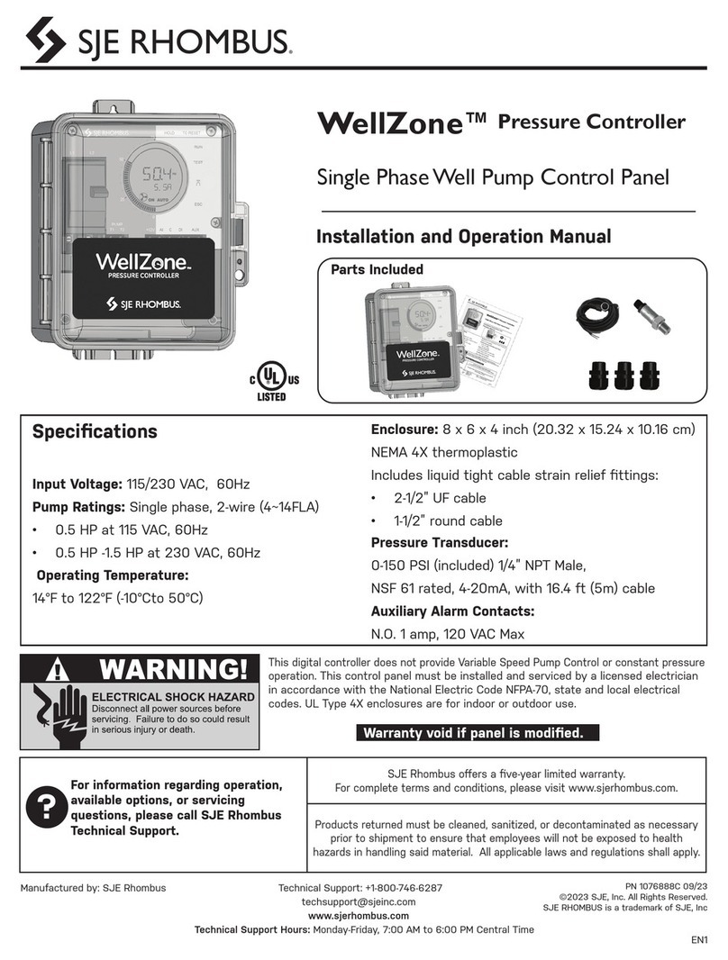
SJE Rhombus
SJE Rhombus WellZone Installation and operation manual
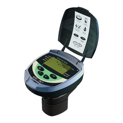
Galcon
Galcon 6100 Series Installation and operating instructions
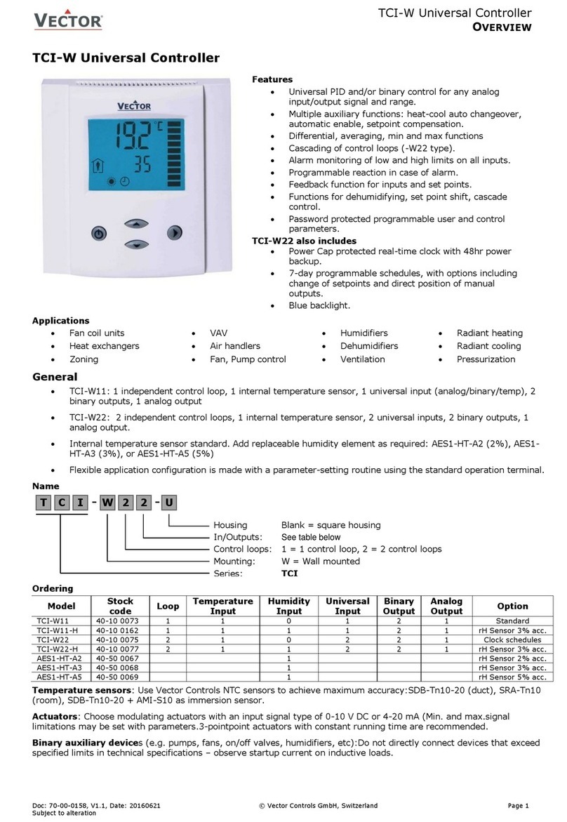
Vector
Vector TCI-W manual

IFM Electronic
IFM Electronic ecomot100 EC2112 installation instructions
Mitsubishi Electric
Mitsubishi Electric NZ2GF-CCB user manual
Viessmann
Viessmann VITOTRONIC 300 operating instructions
