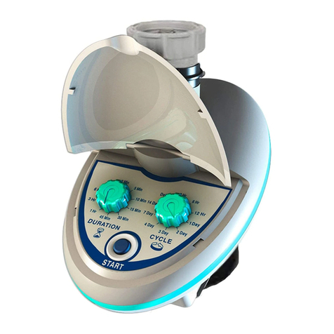
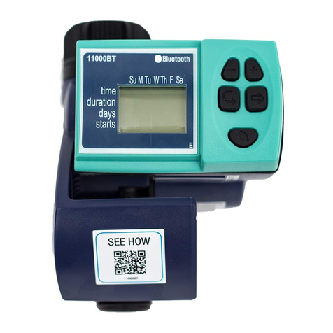
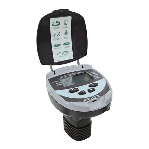
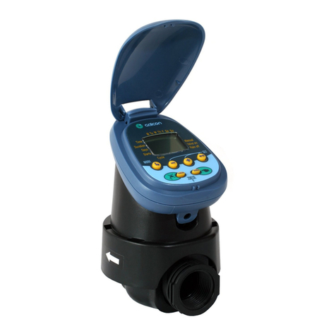
Galcon 6100 Series User manual

Main Features (Not including “S” series*):
• Independent programming of each individual valve
• Weekly or cyclical programming
• 4 operations per day at each valve in weekly program mode
• Irrigation duration: 1 minute to 12 hours
• Irrigation frequency in cyclical program: from once a day to once every thirty days
• Waterproof (IP68)
• Weather resistant
• Irrigation duration modifiable as a function of percentage entered
• Operation of 1 to 6 valves and from master valve
• Option of manual computerized operation of each individual valve
• Option of sequential manual operation
• Powered by 9V alkaline batteries
• Option to connect to a sensor
• Operational temperature -10°C to 70°C
* The “S” series features are detailed in Chapter 7
Battery Operated Irrigation Controller
Installation and Operating Instructions
6100 Series

2
1. Irrigation Controller Parts Identification..................................................................................................................... 4
2. Manual-Mechanical Operation............................................................................................................................................................. 4
3. Installing the Controller in the System........................................................................................................................... 5
3.1 Battery Connection............................................................................................................................................................................................. 5
3.2 Installing on the Wall..................................................................................................................................................................................... 6
3.3 Installing on the Wall..................................................................................................................................................................................... 7
3.4 Wiring the Controller to a 2-wire Solenoid................................................................................... 8
3.5 Wiring the Controller to a 3-wire Solenoid................................................................................... 9
4. Irrigation Programming.............................................................................................................................................................................................. 10
4.1 Setting the Current Time and Day of the Week............................................................. 11
4.2 Switching Between AM/PM and 24 Hour Time Format............................11
4.3 Valve Selection................................................................................................................................................................................................................. 12
4.4 Setting the Irrigation Duration........................................................................................................................................... 12
4.5 Selecting Days of the Week for Irrigation......................................................................................... 13
4.6 Setting Irrigation Start Times................................................................................................................................................. 14
4.7 Example: Programming a Weekly Irrigation Program..................................... 14
5. Additional Functions........................................................................................................................................................................................................... 16
5.1 One-time Irrigation............................................................................................................................................................................................... 16
5.2 Periodic Irrigation..................................................................................................................................................................................................... 16
5.3 Setting a Day and Time for Opening in A
Periodic Plan and in a one-time Plan............................................................................................................. 17
5.4 Example of Defining a Periodic Irrigation Program................................................ 17
5.5 Computerized Manual Operation of the Valve.................................................................... 18
5.6 Serial Manual Operation for all Valves......................................................................................................... 19
5.7 Downtime........................................................................................................................................................................................................................................ 20
5.8 Addition and Reduction in Percentages................................................................................................ 20
Table of Contents

3
6. Additional Views............................................................................................................................................................................................................................... 21
6.1 Valve in Waiting Mode.............................................................................................................................................................................. 21
6.2 Blinking Alert for Low Batteries....................................................................................................................................... 22
6.3 Steady Alert for Low Batteries............................................................................................................................................. 22
6.4 Missing Definition in the Irrigation Program............................................................................. 22
6.5 Sensor........................................................................................................................................................................................................................................................ 23
7. Instructions for Series S Controllers
DC-1S, DC-2S, DC-4S, DC-6S......................................................................................................................................................................... 24
7.1 Main Features of the S Series.............................................................................................................................................. 24
7.2 Defining the Duration of Irrigation in a
Periodic Irrigation Program.......................................................................................................................................................... 24
7.3 Opening a Window After the Start Time.............................................................................................. 26
7.4 Sensor........................................................................................................................................................................................................................................................ 26
8. Maintenance, Troubleshooting and Repair......................................................................................................... 27
9. Warranty Certificate.............................................................................................................................................................................................................. 28

4
1. Irrigation Controller Parts Identification
1. Cover
2. Controller display
3. Push buttons
4. Adaptor
5. Solenoid
6. Mechanical operation lever
7. Hydraulic valve
8. Battery compartment cover
The irrigation valve can be opened regardless of the controller’s operation.
This mode is useful when immediate irrigation is required, and the controller
is not assembled yet. The operating lever is below the solenoid.
The lever has 3 positions:
1. AUTO – Mid position
2. CLOSE - Rotating clockwise
3. OPEN - Rotating counter clockwise
NOTE: In normal working conditions,
the lever should be in the middle, in
AUTO position.
2. Manual-Mechanical Operation

5
3. Installing the Controller in the System
3.1 Battery Connection
a. Open the battery compartment cover (1).
b. lnsert the batteries according to your model (for 9V controller one battery
needs to be inserted, and for 18V two batteries) (2).
NOTE - AII controller display elements appear briefly on the display,
followed by a blinking at 12:00. The controller is now ready to be
programmed.
Replace the battery compartment cover, making sure the pins are in
place, and then rotate the cover 1/8 of a turn to the right. Be sure to do
so, otherwise the battery cover pins might break!
CLOSE

6
The controller can be installed on the solenoid or on the wall.
Place the base of the controller (1) on the solenoid (2). Position the
solenoid wires so that they will go through the opening in the base.
Connect the controller (3) to the base.
NOTE: Assembly of a filter upstream of the valve is mandatory!
3.2 Installing on the Wall
The controller makes a soft click sound when
properly connected to the base.
3
1
2

7
a. Attach the wall mounting plate (1) on the wall using 3 screws (2) (not
included).
b. Remove the bracket (3) from the controller and mount it on the wall
adapter by sliding it downwards onto the mounting plate.
c. Press the controller (4) into the bracket.
The controller fits the bracket with a small click
3.3 Installing on the Wall

8
3.4 Wiring the Controller to a 2-wire Solenoid
The controllers have pairs of red and black wires numbered for the number
of valves in the controller. One set of wires (black and red) is stamped with
the letter M, representing the master valve, and one set of wires (yellow)
with the letter S representing the sensor connection.
1. Connect each pair of cables coming out of the controller to each pair of
solenoid cables.
2. The wiring area should be protected from moisture by an airtight box.
3. Connect the black wire coming out from the solenoid to the black wire
of the controller, according to the valve number. The valve number is
marked on the wires on the controller
4. Connect the red wire from the solenoid to the corresponding red wire in
the controller, according to the valve number
NOTE - If you install a master valve, it will open automatically with
each valve. No special programming is needed.
NOTE: The controller and its cables are waterproof. In order to
preserve the waterproof characteristics it is important not to expose
the wires that are not being used.
NOTE - Do not uncover the master valve or sensor wires, unless
using master/sensor

9
3.5 Wiring the Controller to a 3-wire Solenoid
Labeled cables (1) emerge from the controller. The end of each cable is
protected by a cover that must be removed prior to connecting the cable.
NOTE: The controller and its cables are waterproof. In order to
preserve the waterproof characteristics it is important not to expose
the wires that are not being used.
To preserve watertightness the following instructions need to be followed:
• Connect the cables to the valves (3) using the special waterproof
connectors (2) supplied with the product. See illustration.
1. Cut the cover of the cable coming out of the controller (1) near the end of
the cable and expose the cable leads from the outer black insulating sleeve
only. The solenoid cables have three wires: white, red and black. Do not
expose the three wires from their colored insulation
2. Connect the wires to the waterproof connector (2).
Connect the valves to the cables emerging from the controller according to the
illustration and explanation below.

10
4. Irrigation Programming
This section describes the programming steps for a simple irrigation
schedule.
The next section deals with more advanced irrigation operations.
The irrigation controller is programmed with the aid of 4 buttons:
Enter Button - Used to switch between the desired programming
modes
Set Button - Used to select the parameter to be changed (e.g. hour,
minute, etc.) The selected parameter can only be changed when its
icon is blinking on the display.
Plus Button - Increases the value of the selected parameter (e.g. adds
an hour).
Minus Button - Decreases the value of the selected parameter (e.g.
decreasing an hour).
SET
PLUS
MINUS
ENTER

11
4.1 Setting the Current Time and Day of the Week
The default time format is the AM/PM.
There is also the 24-hour time format.
To switch between the two formats:
1. Press “Enter” several times until the
“Clock” appears.
2. Press “Set” . The hour digits blink.
3. Press “Plus” and “Minus” buttons
simultaneously. The clock reading
switches from AM/PM to a 24-hour time
display or vice versa. You can switch the
time display format at any step in the programming process.
To enable the irrigation controller to operate the irrigation system at the
correct times, the current time and day of the week must first be set.
1. Press “Enter” several times until the
“Clock” appears.
2. Press “Set” . The hour digits will blink. Set the
current hour using “Plus” or “Minus” (note the
AM and PM terms).
Another click on the arrow will cause the
minute digit to flash. Set the desired duration of
minutes using plus and minus .
3. Press “Set” . A blinking arrow appears at the top of the display. Place the
arrow in front of the current day of the week using the “Plus” or “Minus” buttons.
If the most recent data item stops blinking before you finish programming it, press
“Set” to continue the programming process.
4.2 Switching Between AM/PM and 24 Hour Time Format

12
4.3 Valve Selection
This section does not apply to the DC-1 and DC1S models
An independent irrigation schedule program must be set for each valve
individually. First select the main valve, and then proceed with the irrigation
program as specified.
1. Press Enter until appears.
2. Press Set . A blinking arrow will appear
at the bottom of the display.
3. Place the arrow in front of the valve you
want to program using and .
4. Press Enter to proceed to the next
step.
DC4
valve
manual
now
duration
days
starts
4.4 Setting the Irrigation Duration
This setting determines how long the irrigation lasts.
1. Press “Enter” until “Duration” appears.
2. Press “Set” . The hour digit blinks. Set the desired number of hours by
pressing “Plus” or “Minus” buttons. Press “Set” again - the
minute digits blink. Set the desired number of minutes by pressing “Plus”
or “Minus” buttons.
3. Press “Enter” to proceed to the next step.

13
4.5 Selecting Days of the Week for Irrigation
This setting determines on which days of the week the irrigation controller
will operate the selected valve.
1. Press “Enter” until “Days” appears.
2. Press “Set” . A blinking arrow appears at the top of the display, under
Monday.
3. Move the blinking arrow to the desired day of the week by pressing “Set”
.
4. Selecting/adding irrigation days: Press “Plus” . The arrow under the
selected day stops blinking, moves one position to the right, and blinks
under the next day of the week. You can select additional days of the week
in the same manner.
5. Canceling Scheduled Irrigation Days: Bring the blinking arrow under the day
you want to cancel. Click Set . The arrow below the selected day will
disappear, and the flashing arrow will move to the right, below the next day
of the week. Additional days can be canceled in the same way.
6. When the blinking arrow reaches Sunday, pressing again displays
the word ONCE in the center of the display, and the symbol “Cyclical”
appears at the upper right corner of the display. To return to the “Selecting/
Adding Irrigation Days” mode, press “Set” once or twice. Click to
go to the next step.
DC4
valve
manual
now
duration
days
starts

14
4.6 Setting Irrigation Start Times
1. In this step, up to 4 separate irrigation start times can be programmed
per day. The selected valve will open at each of the established start
times, for the irrigation duration set as described in Section 4.4.
2. Press “Enter” until “STARTI” appears. The word “OFF” or the last
start time that was entered will appear on the display.
3. Press “Set” . The displayed item (or the last start time entered) will
blink.
4. Set the desired start time
( note the AM and PM terms) by
pressing “Plus” or “Minus” . Repeat
actions 2-3 for programing II-III-IV if
required.
5. To cancel a specific start time, select it by
pressing “Enter” and press “Set”
. The hour digits will blink. Press “Plus” or “Minus” until the word
“OFF” appears on the display.
6. To program another valve, select it and repeat the above steps, starting
from Section 4.3.
4.7 Example: Programming a Weekly Irrigation Program
Suppose you want to program the irrigation controller so that it irrigates three
times a day. In the 24-hour format: 08:00, 13:00 and 19:00, for two and a half
hours at a time, on Tuesdays and Fridays.
To switch to 24-hour format, see Section 4.3 (If you are using the DC-1 irrigation
controller, start with step 4 below.)

15
1. Press Enter until appears.
2. Click Set . A flashing arrow will appear at the bottom of the display.
3. Press or to move the arrow to the valve number you want to
program.
4. Press ENTER until the icon appears.
5. Click Set . The hour digit will flash. Press or until the
number 2 will be displayed.
Click Set . The minute digit will flash. Press or until the
number 30 will appear in units of minutes.
6. Press Enter . The days icon will be displayed.
7. Click Set . A flashing arrow will appear at the top of the display,
below Monday. Press Set until the flashing arrow appears below
Tuesday, and then click on the plus symbol . The arrow below
Tuesday will stop flashing and move to the right, to Wednesday. Press
Set twice to move the arrow to Friday, and then click Plus .
8. Press Enter ; the start time STARTI will be displayed. Click Set
. The hours digit will flash.
9. Set the start time to 08:00 by clicking on the plus or minus
sign. Repeat this step to set the second start time (2) STARTII to 13:00,
and the third start time (3) STARTIII to 19:00.
10. Press Enter for the fourth start time (4) START IV will be displayed.
Press and the hours digit will flash.
11. Press the plus or minus sign until OFF is displayed. The fourth
valve opening is now canceled.

16
5.1 One-time Irrigation
In this operation we program the controller to run the irrigation system
once, for the duration and the time set.
Note: The duration is determined according to Section 4.4
1. Press ENTER until appears.
2. Press Set several times (for all days of
the week) until the icon appears and
the word ONCE blinks in the display.
3. Go to Section 4.5 to determine the start day
and time.
5.2 Periodic Irrigation
In this operation we program the controller to operate the irrigation system
once for a fixed number of days, for the time allotted to irrigation.
Note: The duration of the valve opening is determined according to
Section 4.4.
1. Press Enter until the icon
appears.
2. Press Set repeatedly (for all days of
the week) until the periodic symbol
appears, and the word Once will flash on
the display.
3. While the display is blinking, press or
. The display will show the number of
days between irrigations (irrigation cycle). For example, if you set 2 days,
irrigation will take place every two days for the determined time.
5. Additional Functions

17
5.3 Setting a Day and Time for Opening in A Periodic Plan and in
a one-time Plan
In these programs it is possible to determine in advance the opening time of
the valve. The number of days until the opening appears on the screen to the
right of the opening time 0 above the word “days”, meaning that the program
will start today; 1 means that the program will start tomorrow, and so on (up
to 30 days.)
1. Press Enter until STARTI appears.
The display will show the last programmed
opening time.
2. Click Set . The time display will flash.
3. Set the desired opening time using (or
). Pay attention to the AM and PM terms.
4. Press Set until the number to the right
of the start hour flashes (the number above
the word “days”).
5. Set the number of days until the opening of the valve with or .
Note: Opening of 2, 3 and 4 are canceled in this program.
5.4 Example of Defining a Periodic Irrigation Program
Suppose you want to program the irrigation controller to open the valve at
12:45 at noon, for an hour, once every 5 days.
1. Determine the duration of irrigation in accordance with Section 4.4:
defining the duration of the irrigation. Press Enter until the icon
appears. Press and set the duration of the irrigation by pressing
or .

18
This operation turns on the selected valve for the irrigation time set in the
program. The valve will close automatically at the end of the predetermined
irrigation duration.
Note that the originally defined program
continues to run according to the
determined times.
For setting-up times:
1. Press Enter until the valve icon
appears. Select a valve according to
Section 5.3 Valve Selection
2. Press Enter until the ‘Manual
watering’ icon appears
3. Press to open the valve. The word ‘On’
will appear in the display. After 5 seconds
the remaining irrigation time appears ,
counting down on the monitor.
To close manually, press Enter until
the manual watering icon appears, and press in the display. The
word ‘off’ will appear.
5.5 Computerized Manual Operation of the Valve
2. Press Enter until the days icon appears.
3. Press Set several times (for all days of the week) until the word
Once flashes on the display.
4. While the display is blinking, press or until “5 days” appears on
the display, which is the frequency of the irrigation.
5. Press Enter . The display will show .STARTI.
6. Click Set . The hours display will flash.
7. Set the start times and minutes, by pressing or , as described in
Section 4.6.

19
Note: It is possible to turn on up to 2 valves simultaneously,
by repeating the steps outlined above.
It is possible to operate all the valves sequentially, one after the other.
1. Press Enter until the clock icon appears.
2. When nothing is flashing on the display, press and hold for 5
seconds. Valve No. 1 will open and operate for the duration of the
programmed irrigation. When valve No.1 closes, valve No. 2 will open and
so on, until the end. All valves programmed to be opened will flash. You
can intervene in the process. Clicking on closes the current valve
and opens the next valve after it.
Note: You can exit this screen only after having opened all valves.
5.6 Serial Manual Operation for all Valves

20
5.7 Downtime
This makes it possible to temporarily cancel the control of the controller on
the valves, for example when it rains. The irrigation schedule is maintained,
but irrigation is not carried out.
The shutdown operation prevents irrigation in all valves.
1. Press Enter until the clock icon
appears.
2. Press and hold (more than 5 seconds.)
The icon (no irrigation) will be
displayed flashing in front of the caption
“Downtime.” The controller is disabled now.
3. To return control to the controller, press
Enter until the clock icon appears,
and then press continuously until the icon disappears.
4. Downtime may be carried out while the valve is turned on.
5. In downtime mode, if you accidentally try to turn on a valve manually or
if it reached its time to open, the word ‘rain’ will appear and the valve will
not open.
It is possible to add or reduce the duration of irrigation in all taps
simultaneously in the form of percentages.
Example: If the irrigation duration is one hour and we add 10%, the new
irrigation duration will be one hour and 6 minutes (66 minutes).
5.8 Addition and Reduction in Percentages
Table of contents
Other Galcon Controllers manuals

Galcon
Galcon AC 4 User manual

Galcon
Galcon 7001D User manual

Galcon
Galcon S Series User manual

Galcon
Galcon Galileo Manual

Galcon
Galcon Dc-1 User manual

Galcon
Galcon 61 Series User manual

Galcon
Galcon Gal Pro DC User manual

Galcon
Galcon DC-11SF User manual

Galcon
Galcon 9001 E-Z User manual

Galcon
Galcon 7101BT User manual