manuals.online logo
Brands
  1. Home
  2. •
  3. Brands
  4. •
  5. MAMAC SYSTEMS
  6. •
  7. Transducer
  8. •
  9. MAMAC SYSTEMS PR-276 Manual

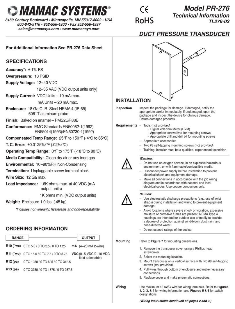
MAMAC SYSTEMS PR-276 Manual

Inspection Inspectthe package fordamage.If damaged,notifythe
appropriatecarrierimmediately.If undamaged,open
the package and inspectthe deviceforobviousdamage.
Returndamaged products.
Requirements
•Tools(notprovided)
-DigitalVolt-ohmMeter(DVM)
-Appropriatescrewdriverformounting screws
-Appropriatedrill and drill bitformounting screws
•Appropriateaccessories
•Two#8 self-tapping mounting screws(notprovided)
•Training:Installermustbe aqualified,experienced
technician
Warning:
•Donotuseon oxygen service,inan
explosive/hazardousenvironment, orwith
flammable/combustiblemedia.
•Disconnectpowersupplybeforeinstallation toprevent
electricalshock and equipmentdamage.
•Makeall connectionsinaccordancewiththe job wiring
diagram,and inaccordancewithnationaland local
electricalcodes.Usecopperconductorsonly.
Caution:
•Useelectrostaticdischarge precautions(e.g., useof
wriststraps)during installation and wiring toprevent
equipmentdamage.
•Avoidlocationswheresevereshock orvibration,
excessivemoistureorcorrosivefumesarepresent.
NEMAType 4housingsareintended foroutdooruse
primarilytoprovide adegree ofprotection against
wind-blowndust, rain,and hose-directed water.
•Donotexceed ratingsofthe device.
ModelPR-276
TechnicalInformation
TI.276-01
DuctPressureTransducer
Accuracy*:±1%FS
Overpressure:10 psid
SupplyVoltage:12-40 VDC
12-35 VAC(VDC output
unitsonly)
SupplyCurrent: VDC Units-10 mAmax.
mAUnits-20 mAmax.
Enclosure:18 GaC.R.SteelNEMA4(IP-65)6061Taluminumprobe
Finish:Baked on enamel-PMS2GR88B
Conformance:EMCStandardsEN50082-1(1992)
EN55014(1993)/EN60730-1(1992)
CompensatedTempRange:25ºF-150ºF(4ºC-65ºC)
T.C.Error:±0.0125%/ºF(.02%/ºC)
Operating TempRange:0ºF-175ºF(-18ºC-80ºC)
MediaCompatibility:Clean dryairoranyinertgas
Environmental:10-90%RH Non-Condensing
Termination:Unpluggablescrewterminalblock
WireSize:12 Gamax.
LoadImpedance:1.6Kohmsmax.at40 VDC (mAoutputunits)
1Kohmsmin.(VDC outputunits)
Weight: 1.0lbs.(.45 kg)
*Includesnon-linearity,hysteresisand non-repeatability
FORADDITIONALINFORMATION
SEE PR-276 DATASHEET
SPECIFICATIONS
RANGEOUTPUT
INSTALLATION
Mounting RefertoFigure-7formounting dimensions.
1.Removethe transducercoverusing aPhillipshead
screwdriver.
2.Selectthe mounting location.
3.Mounttransduceron averticalsurfacewithtwo#8
self-tapping screws(notprovided).
4.Pull wiresthrough bottomofenclosureand make
necessaryconnections.
5.Replacecoverand makepneumaticconnections.
!
R10 (”wc)0TO5.0/0TO2.5/0TO1.25 mA(4-20 mA2-wire)
R11 (”wc)0TO15.0/0TO7.5/0TO3.75 VDC (0-5VDC or0-10VDC field
Selectable)
R12 (pa)0TO1250 /0TO625 /0TO312.5
Legend
S=Span Adjust
Z=ZeroAdjust
+=SupplyVoltage
-=Common (Neutral)
0=Output
Legend
S=Span Adjust
Z=ZeroAdjust
+=SupplyVoltage
-=Signal
PR-276 PressureTransducerswithmAOutput.
Wiring PR-276 UnitswithVDC Output
PR-276 pressuretransducerswithVDC outputarefieldselectable0-5
VDC or0-10 VDC outputand can be powered witheither12-40 VDC
or12-35VAC.The following describesthe properwiring ofthesepressure
transducerswithVDC output:
1.Removethe blue terminalblock bycarefullypulling itoff the circuit
board
2.Locatethe (+),(-),and (0)terminalmarkingson the board.
3.Attachthe powerwirestothe (+)and (-) terminals.The (-) terminal
isalsothe negativeoutputterminal.
4.Connectthe (0)terminal,whichisthe positiveVdcoutputterminal,
tothe controller’sinputterminal.
5.Re-insertthe terminalblock tothe circuitboardand applypowerto
the unit.
6.Check the appropriateVdcoutputusing avoltmeterseton DC volts
across the (0)and (-) terminals.
+– ZS
+–0 ZS
PR-276 PressureTransducerswithVDC Output.
ModelPR-276
TechnicalInformation
TI.276-01
DuctPressureTransducer
TYPICALAPPLICATIONS(wiring diagrams)
Figure-1and Figure-2
Illustratetypicalwiring diagramsforthe PR-276 Series,4-
20 mA,two-wireoutputductpressuretransducers.
Figure-1Wiring formAOutputDuctPressure
TransducerswithExternalDC Power
Supply.
Figure-2Wiring formAOutputDuctPressure
TransducerswhereControllerorMeterhas
InternalDC PowerSupply.
Page 2of4
+
–+
–
+
–
mAOutput
TranducerOnly12-40 VDC
PowerSupply
Controller/
Meter/
Recorder
Shield/
Ground
InputSignal
Common
+
–
mAOutput
TranducerOnly
+
–
Controller/
Meter/
Recorder
Shield/
Ground
InputSignal
Common
Wiring Usemaximum12 AWGwireforwiring terminals.
RefertoFigures1,2,3,&4forwiring information
and Figures5&6forjumperdesignations.
Wiring PR-276 UnitswithmAOutput
PR-276 pressuretransducersare4-20 mAoutputunitspowered
witha12-40 VDC supply.The following describesthe properwiring
ofthesepressuretransducerswithmAoutput:
1.Removethe blue terminalblock bycarefullypulling
itoff the circuitboard.
2.Locatethe [+]and [-]terminalmarkingson the board.
3.Attachthe supplyvoltage tothe [+]lead.
4.Connectthe 4-20 mAoutput([-]terminal)tothe
controller’sinputterminal.
5.Ensurethatthe powersupplycommon isattached to
the common busofthe controller.
6.Re-insertthe terminalblock tothe circuitboard
and applypowertothe unit.
7.Check forthe appropriateoutputsignalusing
aDVMseton DC milliampsconnected inseries
withthe [-]terminal.
Caution:Thisproductcontainsahalf-waverectifier
powersupplyand mustnotbe powered off transformers
used topowerotherdevicesutilizing non-isolated full-
waverectifierpowersupplies.
Caution:If you areusing grounded AC,the hotwire
mustbe on the (+)terminal.Also,ifyou areusing a
controllerwithoutbuilt-inisolation,usean isolation
transformertosupplythe PR-276 transducer.
Caution:When multiplePR-276 unitsarepowered from
the sametransformer,damage will resultunless all 24G
powerleadsareconnected tothe samepowerlead on
all devices.It ismandatorythatcorrectphasing be
maintained when powering morethan one devicefrom
asingletransducer.
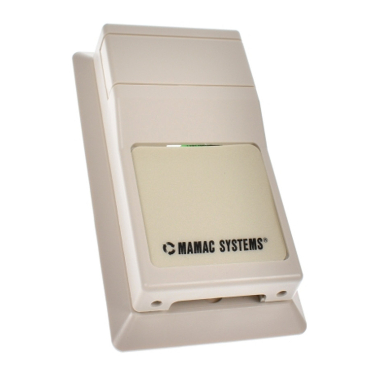
ADJUSTMENTS
JumperJumperselectionsvaryaccording tothe pressure
transducer(mAorVDC).
Selection The following describesthe possibleselectionsfor
eachmodel.
JumperSelectionsforPR-276 PressureTransducers
withmAOutputs
The possiblerange configurationsand jumper
selectionsforpressuretransducerswithmAoutputs
areshowninTable-1and Figure-5,respectively.
JumperSelectionsforPR-276 PressureTransducers
withVDC Output
The possiblerange configurationsand jumper
selectionsforpressuretransducerswithVdcoutputs
areshowninTable-2and Figure-6,respectively.
Table-1RangeConfigurationsforPressureTransducerswith
mAOutputs
Range:ARange:B
ZS
+–
Range:C
Figure-5JumperSelectionsforPressureTransducerswith
mAOutputs.
Table-2RangeConfigurationsforPressureTransducers
withVDC Outputs
0to5Vdc0to10 Vdc
RANGECONFIGURATIONS
OUTPUTCONFIGURATIONS
Range ARange B
Range C
ZS
+–ZS
+–
+–0ZS
+–0ZS
+–0ZS
+–0ZS
+–0ZS
F
igure-3and Figure-4
Illustratetypicalwiring diagramsforthe PR-
276,0-5/0-10 VDC outputductpressure
transducers.
Figure-3Wiring forVDC OutputDuctPressure
TransducersWhen Applied withACSupply.
Figure-4Wiring forVDC OutputDuctPressure
TransducersWhen Applied withDC Power
Supply.
ModelPR-276
TechnicalInformation
TI.276-01
DuctPressureTransducer
Page 3of4
A
RangeB C
RangeConfigurations(inches,w.c.)
OutputConfigurations
0to5Vdc0to10 Vdc
A
RangeB C
RangeConfigurations(pa)
OutputConfigurations
0to5Vdc0to10 Vdc
R10
R11 0to5.0
0to15.00to2.5
0to7.50to1.25
0to3.75
R12
R13 0to1250
0to3750 0to625
0to1875 0to312.5
0to937.5
A
RangeB C
RangeConfigurations(inches,w.c.)
R10
R11 0to5.0
0to15.00to2.5
0to7.50to1.25
0to3.75
A
RangeB C
RangeConfigurations(pa)
R12
R13
0to1250
0to3750
0to625
0to1875
0to312.5
0to937.5
Figure-6JumperSelectionsforPressureTransducers
withVDC Outputs.
+
–
Controller/
Meter/
Recorder
Shield/
Ground
Input
Signal
Common
12-40 VDC
PowerSupply
+
–
VDC Output
TransducerOnly
Common
+
–
Supply
Signal0
Input
Signal
Common
+
–
Controller/
Meter/
Recorder
Shield/
Ground
Input
Signal
Common
12-35 VAC
Transformer
Hot
Neutral
+
–
VDC Output
TransducerOnly
Common
+
–
Supply
Signal0
TransducerThisisarough functionalcheck only.
Operation 1.Adjustthe pressuretoobtainmaximumoutput
signalforappropriaterange.
2.Outputshouldbe 20 mAor5or10 VDC.
3.Adjustthe pressuretoobtainminimumoutput
signal.
4.Outputshouldbe 4mAor0VDC.
Note:The PR-276 isahighlyaccuratedevice.For
applicationsrequiring ahigh degree ofaccuracy,
the useoflaboratoryqualitymetersand gauges
arerecommended.
Figure-7PR-276 DuctPressureTransducerDimensionsshownininches
and millimeters(mm).
TI.276-01
4.00”
(101.60
)
2.658”
(67.51)
3.25”
(82.55)
3.00”(76.21)3.00”(76.21)
5.00”(127.00)
2.25”
(57.15)
8.00”
(203.20)
CALIBRATIONAll unitsarefactorycalibrated tomeetorexceed
published specifications.If fieldadjustmentis
necessary,followthe instructionsbelow.
Calibration ofPR-276 mAUnits
1.Connectterminals(+)and (-) tothe appropriate
powersource.
2.Connectthe DVMinserieson the (-) terminal.
3.Applylowpressuretothe unitand carefullyadjust
the zerotrimmer(Z)toobtaindesired lowoutput.
4.Applyhigh pressuretothe unitand adjustspan
trimmer(S)toobtainthe desired high output.
5.Repeatsteps3and 4until desired calibration is
achieved.
Calibration ofPR-276 VDC Units
1.Connectterminals(+)and (-) tothe appropriate
powersource.The (-) terminalisalsothe negative
outputterminal.
2.Connectthe DVMon DC voltsacross (0)and (-)
terminal.
3.Applylowpressuretothe unitand carefullyadjust
the zerotrimmer(Z)toobtaindesired lowoutput.
4.Applyhigh pressuretothe unitand adjustspan
trimmer(S)toobtainthe desired high output.
5.Repeatsteps3and 4until desired calibration is
achieved.
ForTechnical/Application Assistance contactyournearestoffice
.
MAMACSystemsInc.reservesthe righttochange anyspecifications
withoutnoticetoimproveperformance,reliability,orfunction ofour
products.
CHECKOUT1.Verifythatthe unitismounted inthe correct
position.
2.Verifyappropriateinputsignaland supplyvoltage.
Caution:Neverconnect120 Vactothese
transducers.NeverconnectACvoltage toaunit
intended forDC supply.
3.Verifyappropriateconfiguration range.
MAINTENANCERegularmaintenanceofthe totalsystemis
recommended toassuresustained optimum
performance
FIELDREPAIRNone.Replacewithafunctionalunit.
WARRANTYSee DataSheetforadditionalinformation.
ModelPR-27
6
TechnicalInformation
TI.276-01
DuctPressureTransducer
DIMENSIONALDATA
Page 4of4

Other MAMAC SYSTEMS Transducer manuals

MAMAC SYSTEMS PR-243 Manual

MAMAC SYSTEMS

MAMAC SYSTEMS PR-243 Manual

MAMAC SYSTEMS HU-224 User manual

MAMAC SYSTEMS

MAMAC SYSTEMS HU-224 User manual

MAMAC SYSTEMS PR-274 Manual

MAMAC SYSTEMS

MAMAC SYSTEMS PR-274 Manual

MAMAC SYSTEMS PR-264 Manual

MAMAC SYSTEMS

MAMAC SYSTEMS PR-264 Manual

MAMAC SYSTEMS PR-283 Manual

MAMAC SYSTEMS

MAMAC SYSTEMS PR-283 Manual

MAMAC SYSTEMS PR-276 Manual

MAMAC SYSTEMS

MAMAC SYSTEMS PR-276 Manual

MAMAC SYSTEMS EP-313 User manual

MAMAC SYSTEMS

MAMAC SYSTEMS EP-313 User manual

MAMAC SYSTEMS EP-311 Series Manual

MAMAC SYSTEMS

MAMAC SYSTEMS EP-311 Series Manual

MAMAC SYSTEMS PR-264 Manual

MAMAC SYSTEMS

MAMAC SYSTEMS PR-264 Manual

MAMAC SYSTEMS PR-274 Manual

MAMAC SYSTEMS

MAMAC SYSTEMS PR-274 Manual

MAMAC SYSTEMS HU-224 User manual

MAMAC SYSTEMS

MAMAC SYSTEMS HU-224 User manual

Popular Transducer manuals by other brands

Lumel P18S user manual

Lumel

Lumel P18S user manual

Balluff BTL7-P511-M Series Condensed guide

Balluff

Balluff BTL7-P511-M Series Condensed guide

MKS 523210-0-0E-T quick start guide

MKS

MKS 523210-0-0E-T quick start guide

Balluff BTL7-V50T-M-P-C003 Series user guide

Balluff

Balluff BTL7-V50T-M-P-C003 Series user guide

Setra Systems 269 installation guide

Setra Systems

Setra Systems 269 installation guide

RDP Group D5 Series Technical manual

RDP Group

RDP Group D5 Series Technical manual

M-system 18HZ instruction manual

M-system

M-system 18HZ instruction manual

turck HART IM33-11-Hi/24VDC Series Safety manual

turck

turck HART IM33-11-Hi/24VDC Series Safety manual

Garmin gWind Race installation instructions

Garmin

Garmin gWind Race installation instructions

Campbell CS451 instruction manual

Campbell

Campbell CS451 instruction manual

WIKA F1106 operating instructions

WIKA

WIKA F1106 operating instructions

GE Sensing RPT 301 user manual

GE

GE Sensing RPT 301 user manual

Siemens SITRANS T3K PA instruction manual

Siemens

Siemens SITRANS T3K PA instruction manual

WATANABE ELECTRIC INDUSTRY TW-3K instruction manual

WATANABE ELECTRIC INDUSTRY

WATANABE ELECTRIC INDUSTRY TW-3K instruction manual

HBM T5 Mounting instructions

HBM

HBM T5 Mounting instructions

FuehlerSysteme RAF/A operating manual

FuehlerSysteme

FuehlerSysteme RAF/A operating manual

S+S Regeltechnik PREMASGARD 1110 Operating Instructions, Mounting & Installation

S+S Regeltechnik

S+S Regeltechnik PREMASGARD 1110 Operating Instructions, Mounting & Installation

Airmar TRIDUCER P23 Owner's guide & installation instructions

Airmar

Airmar TRIDUCER P23 Owner's guide & installation instructions

manuals.online logo
manuals.online logoBrands
  • About & Mission
  • Contact us
  • Privacy Policy
  • Terms and Conditions

Copyright 2025 Manuals.Online. All Rights Reserved.