Mesto Neles XH Series Operating and maintenance manual

1 XH 70 en • 4/2020
NELES®
TRUNNION MOUNTED BALL VALVE,
FULL BORE
Series XH
Installation, Maintenance and
Operating Instructions

21 XH 70 en
READ THESE INSTRUCTIONS FIRST!
These instructions provide information about safe handling and operation of the valve.
If you require additional assistance, please contact the manufacturer or manufacturer's representative.
Addresses and phone numbers are printed on the back cover.
SAVE THESE INSTRUCTIONS!
Subject to change without notice.
All trademarks are property of their respective owners.
Table of Contents
1GENERAL..............................................................3
1.1 Scope of the manual ........................................... 3
1.2 Valve description .................................................. 3
1.3 Markings .................................................................. 3
1.4 Specifications......................................................... 4
1.5 Valve approvals ..................................................... 4
1.6 CE marking ............................................................. 4
1.7 Recycling and disposal ....................................... 4
1.8 Safety precautions ................................................ 4
2 TRANSPORTATION, RECEPTION AND
STORAGE ............................................................. 5
3INSTALLATIONANDUSE....................................5
3.1 General ..................................................................... 5
3.2 Installing in the pipeline .................................... 5
3.3 Actuator.................................................................... 6
3.4 Commissioning ..................................................... 6
4MAINTENANCE....................................................6
4.1 Maintenance general.......................................... 6
4.2 Changing the gland packing while
the valve is in the pipeline ................................ 6
4.3 Repair of a jammed or stuck valve while
it is in the pipeline ................................................ 7
4.4 Detaching the actuator ...................................... 7
4.5 Removing the valve from the pipeline ......... 8
4.6 Dismantling the valve ......................................... 8
4.7 Inspection of removed parts ............................ 8
4.8 Replacing parts ..................................................... 8
4.9 Assembly ...................................................................
5TESTINGTHEVALVE...........................................9
6INSTALLINGTHEACTUATOR............................10
6.1 General ...................................................................10
6.2 Installing the M-handwheel operator..........10
6.3 Installing the B1C-series actuator ................10
6.4 Installing the B1J-series actuator ..................10
6.5 Installing other makes of actuators .............10
7TROUBLESHOOTINGTABLE.............................11
8TOOLS................................................................11
9ORDERINGSPAREPARTS..................................11
10 EXPLODED VIEW AND PARTS LIST ...................12
11 DIMENSIONS AND WEIGHTS ........................... 13
12 TYPE CODE .........................................................14
This product meets the requirements set by the Customs Union of the Republic of Belarus,
the Republic of Kazakhstan and the Russian Federation.

1 XH 70 en 3
1 GENERAL
1.1 Scope of the manual
This installation, operation and maintenance manual pro-
vides essential information on trunnion mounted XH series
ball valves. The actuators and instrumentation to be used
with these valves are also discussed briefly. Refer to the
separate actuator and control equipment instruction manu-
als for further information.
1.2 Valve description
Trunnion mounted XH series valves are flanged full bore ball
valves. The valve body is in two parts, fastened together by
body-joint bolting. The ball and shaft are separate. Shaft
blowout is prevented by bonnet and a shoulder machined
on the shaft, and a retainer ring inside the gland.
The valve is either soft or metal seated. Shaft torque is trans-
mitted to the ball through a splined bore in the ball.
The valve is 1-way or 2-way tight depending on the seat
construction. Tightness direction is shown with an arrow on
1-way valves.
Construction details of individual valves are included in the
type code shown on the valve identification plate. To inter-
pret the type code, please refer to the type coding key in this
manual.
Trunnion mounted XH series ball valves are specially
designed for demanding throttling and shut-off service
with high pressure differentials.
1.3 Markings
Body markings are stamped on the body (see Fig. 2).
The identification plate (Fig. 3) is attached to the flange.
Identification plate markings are:
1. Body material
2. Shaft material
3. Trim material
4. Seat material
5. Max and min operating temperature
6. Max shut-off pressure differential / temperature
7. Pressure class
8. Type designation
9. Valve manufacturing parts list no.
10. Model
NOTE:
Selection and use of the valve in a specific application
requires close consideration of detailed aspects. Due to
the nature of the product, this manual cannot cover all the
individual situations that may occur when installing, using
or servicing the valve.
If you are uncertain about use of the valve or its suitability
for your intended purpose, please contact Metso for more
information.
For valves in oxygen service, please see also the separate
installation, maintenance and operating instructions for
oxygen service (see Metso document id:10O270EN.pdf ).
Fig. 1 Construction of a trunnion mounted XH series ball
valve
Fig. 2 Valve markings
Fig. 3 Identification plate
Batch no
Nominal size
pressure rating
ID plate
Manufacturer’s
Body material
Body
material
mark
BODY
TRIM
SHAFT
SEAT
T max
T min
MAX. OPER. ps
at
RATING TYPE
No. MOD
ATTENTION : READ INSTRUCTIONS BEFORE INSTALLATION OR SERVICING. CONTACT METSO FIELD SYSTEMS FOR COPY. MADE BY METSO AUTOMATION
XXXX
(1) (2) (5) (7) (8)
(3) (4) (6) (9) (10)

41 XH 70 en
1.4 Specifications
Face-to-face length: ASME B.16.10
Table 4
long pattern
Body rating: ASME Class 900
Max. pressure differential: see Fig. 4
Temperature range: -50°…+425 °C
-58 °...+797 °F
Tightness: Bi-directional or uni-
directional depending
on seat construction
metal seated ISO 5208 Rate C or Class V
soft seated ISO 5208 Rate B or Class VI
Dimensions: see tables in Section 11
Weights: see tables in Section 11
1.5 Valve approvals
XH-series ball valves meet the requirements set by ASME B
16.34.
Fire safety characteristics are designed according to API 607
and BS 6755.
1.6 CE marking
The valve meets the requirements of the European Directive
2014/68/EU relating to pressure equipment, and has been
marked according to the Directive.
1.7 Recycling and disposal
Most valve parts can be recycled if sorted according to
material. Most parts have material marking. A material list is
supplied with the valve. In addition, separate recycling and
disposal instructions are available from the manufacturer.
A valve can also be returned to the manufacturer for recy-
cling and disposal against a fee.
1.8 Safety precautions
Fig. 4 Maximum allowable Δp in control service
110
120
130
140
150
160
p (bar)
70
80
90
100
0 50 100 150 200 250 300 350 400 450
Temperature (°C)
CAUTION:
Do not exceed the valve performance limitations!
Exceeding the limitations marked on the valve may cause
damage and lead to uncontrolled pressure release.
Damage or personal injury may result.
CAUTION:
Do not dismantle the valve or remove it from the pipe-
line while the valve is pressurized!
Dismantling or removing a pressurized valve will result in
uncontrolled pressure release. Always isolate the relevant
part of the pipeline, release the pressure from the valve
and remove the medium before dismantling the valve. Be
aware of the type of medium involved. Protect people and
the environment from any harmful or poisonous sub-
stances. Make sure that no medium can enter the pipeline
during valve maintenance.
Failure to do this may result in damage or personal injury.
CAUTION:
Beware of the ball cutting movement!
Keep hands, other parts of the body, tools and other
objects out of the open flow port. Leave no foreign
objects inside the pipeline. When the valve is actuated,
the ball functions as a cutting device. Close and detach
the actuator pressure supply pipeline for valve mainte-
nance. Failure to do this may result in damage or personal
injury.
CAUTION:
Beware of noise emission!
The valve may produce noise in the pipeline. The noise
level depends on the application. It can be measured or
calculated using the Metso Nelprof computer program.
Observe the relevant work environment regulations on
noise emission.
CAUTION:
Beware of extreme temperatures!
The valve body may be very hot or very cold during use.
Protect people against cold injuries or burns.
CAUTION:
When handling the valve or the valve package, bear in
mind its weight!
Never lift the valve or valve package by the actuator, posi-
tioner, limit switch or their piping. Place the lifting ropes
securely around the valve body (see Fig. 6). Damage or per-
sonal injury may result from falling parts.
The weights are shown in Section 11.
CAUTION:
Lifting threads in pipe flanges are not to be used for lifting
the entire valve.
CAUTION:
Follow the proper procedures when handling and servic-
ing oxygen valves.

1 XH 70 en 5
2 TRANSPORTATION, RECEPTION AND
STORAGE
Check the valve and the accompanying device for any dam-
age that may have occurred during transport.
Store the valve carefully. We recommend storing indoors in
a dry place.
Do not remove the flow port protectors until installing the
valve.
Move the valve to its intended location just before installa-
tion.
The valve is usually delivered in the open position.
3 INSTALLATION AND USE
3.1 General
Remove the flow bore protectors and check that the valve is
clean inside. Clean the valve if necessary.
3.2 Installing in the pipeline
Flush the pipeline carefully before installing the valve. Make
sure the valve is entirely open when flushing. Foreign parti-
cles, such as sand or pieces of welding electrode, will dam-
age the ball and seats.
The valve may be installed in any position and offers 1-way
or 2-way tightness, see Sections 1.2 and 1.4. However we do
not recommend installing the valve with the actuator on the
underneath side because dirt in the pipeline may then enter
the body cavity and damage the gland packing. The posi-
tion to be avoided is shown in Fig. 7.
It may be necessary to firmly support the pipeline in order
to protect the valve from excess stress. Sufficient support
will also reduce pipeline vibration and thus ensures proper
functioning of the positioner.
To facilitate servicing, it is preferable that the valve be sup-
ported by the body, using pipe clamps and supports. Do not
fasten supports to the flange bolting or to the actuator, see
Fig. 8.
Fig. 5 Storing the valve
Fig. 6 Lifting the valve
CAUTION:
When handling the valve or the valve package as a
whole, bear in mind the weight of the valve or the
entire package!
CORRECT
WRONG
NOTE:
Use screws, nuts, bolts and gaskets equivalent to the fas-
tenings used elsewhere in the pipeline. Center the flange
gaskets carefully when fitting the valve between flanges.
NOTE:
Do not attempt to correct pipeline misalignment by
means of flange bolting.
Fig. 7 Avoid this mounting position
Fig. 8 Supporting the valve

61 XH 70 en
3.2.1 Valve insulation
If necessary, the valve may be insulated. Insulation must not
continue above the upper level of the valve body, see
Figure 9.
3.3 Actuator
The valve open/closed position is indicated as follows:
by an indicator on the actuator
or
by a groove at the end of the ball shaft (parallel to
the ball flow opening).
If there is any uncertainty about the indicator, check the ball
position by the groove.
The actuator should be installed in a manner that allows
plenty of room for its removal.
The upright position is recommended for the actuator cylinder.
The actuator must not touch the pipeline, because pipeline
vibration may interfere with its operation.
In certain cases it may be considered advantageous to pro-
vide additional support to the actuator. These cases will nor-
mally be associated with large actuators, extended shafts, or
where severe vibration is present. Please contact Metso
Automation for advice.
3.4 Commissioning
Ensure that there is no dirt or foreign objects left inside the
valve or pipeline. Flush the pipeline carefully. Make sure that
the valve is entirely open when flushing.
Ensure that all nuts, pipings, and cables are properly fas-
tened.
Check that the actuator, positioner, and switch are correctly
adjusted. Actuator adjustment is explained in Section 6. To
adjust the accompanying device refers to the separate con-
trol equipment instruction manuals.
4 MAINTENANCE
4.1 Maintenance general
Although Metso’s Neles valves are designed to work under
severe conditions, proper preventative maintenance can
significantly help to prevent unplanned downtime and in
real terms reduce the total cost of ownership. Metso recom-
mends inspecting the valves at least every five (5) years. The
inspection and maintenance interval depends on the actual
application and process condition. The inspection and
maintenance intervals can be specified together with your
local Metso experts. During this periodic inspection the
parts detailed in the Spare Part Set should be replaced. Time
in storage should be included in the inspection interval.
Maintenance can be performed as presented below. For
maintenance assistance, please contact your local Metso
office. The part numbers in the text refer to the exploded
view and to the parts list in Section 10, unless otherwise
stated.
4.2 Changing the gland packing while the
valve is in the pipeline
In graphite gland packings, tightness is ensured by contact
between the gland follower and the packing rings.
The gland packing (69) must be changed if leakage occurs
even after the hex nuts (18) have been tightened.
Make sure that the valve is not pressurized.
Detach the actuator and bracket according to the
instructions in Section 4.4.
Remove the key (10).
Fig. 9 Insulation of the valve
NOTE:
When installing the actuator on the valve, make sure that
the valve package functions properly. Detailed informa-
tion on actuator installation is given in Section 6 or in the
separate actuator instructions.
Insulation
CAUTION:
Observe the safety precautions mentioned in Section
1.8 before maintenance!
CAUTION:
When handling the valve or the valve package as a
whole, bear in mind the weight of the valve or the
entire package!
NOTE:
When sending goods to the manufacturer for repair, do
not disassemble them. Clean the valve carefully and flush
the valve internals. For safety reasons, inform the manufac-
turer of the type of medium used in the valve (include
material safety datasheets (MSDS)).
NOTE:
In order to ensure safe and effective operation, always use
original spare parts to make sure that the valve functions
as intended.
NOTE:
For safety reasons, replace pressure retaining bolting if the
threads are damaged, have been heated, stretched or cor-
roded.
CAUTION:
Do not dismantle the valve or remove it from the pipe-
line while the valve is pressurized!

1 XH 70 en 7
Remove the nuts (18), the disc spring sets (150) the
gland (9A), retainer ring (42) and sleeve (9B).
Remove old packing rings (69). Do not damage the
surfaces of the packing ring counterbore and shaft.
Clean the packing ring counterbore.
Place the new packing rings (69) over the shaft (5).
The gland follower may be used for pushing the rings
into the counterbore. Do not damage packing rings in
the shaft keyway.
Pre-compress the packing rings first either by tight-
ening the gland nuts (with or without disc springs)
to the torque Tt or by tightening the gland with disc
springs to the height H2. See Fig. 10 and the value
from Table 1.
Carry out 3…5 operation cycles with the valve. Suita-
ble range of movement is about 80 %.
It is not necessary to fully close or open the valve
during the operation.
Loosen the gland nuts. Place the disc spring sets
(150) on the gland studs as applicable. Retighten the
nuts (18) to the torque Ttor so that the disc springs
are compressed to the height H2, see Table 1.
If the leakage still occurs when the valve is pressur-
ized, re-tighten the nuts but don't exceed the value
in the Table 1 by 50 % or do not fully compress the
disc springs.
Table 1 Tightening of gland packing
4.3 Repair of a jammed or stuck valve
while it is in the pipeline
Jamming may be due to the ball (3) and seats (7) becoming
clogged with flow medium. They may be cleaned by turning
the ball to the partly open position and flushing the pipe-
line. If this does not help, follow the instructions in the fol-
lowing sections.
4.4 Detaching the actuator
Fig. 10 Gland packing
Valve size Shaft diameter Spring dimensions [mm] Tightening torque
[Nm]
DN NPS mm A H1 H2 T_t
50 2 25 35.5 41 37.4 90
80 3 30 40 45.5 41.5 35
100 4 45 50 59 54 80
150 6 55 50 59 54 100
200 8 85 71 73 66 240
250 10 105 80 90.3 82.7 510
300 12 120 80 90.3 82.7 570
350 14 135 100 142.8 130.2 760
400 16 150 100 163.2 153.3 1260
450 18 165 100 163.2 153.3 1380
500 20 180 100 142.8 130.2 990
600 24 220 100 163.2 153.3 1200
CAUTION:
When handling the valve or the valve package as a
whole, bear in mind the weight of the valve or the
entire package!
CAUTION:
Do not detach a spring-return actuator unless a stop-
screw is carrying the spring force!
NOTE:
Before dismantling, carefully observe the position of the
valve with respect to the actuator and positioner/limit
switch so as to make sure that the package can be properly
re-assembled.

81 XH 70 en
It is generally most convenient to detach the actuator
before removing the valve from the pipeline. If the valve is
small or if it is difficult to access, it may be more practical to
remove the entire package at the same time.
Close and detach the actuator pressure supply pipe-
line and remove control cables.
Unscrew the bracket screws.
Detach the actuator. The actuator can be removed
by hand or with a special tool made for this purpose.
The tool can be ordered from the manufacturer (see
Section 8 “Tools”).
Remove the bracket.
4.5 Removing the valve from the pipeline
Make sure that the valve is not pressurized and that
the pipeline is empty. Make sure that the medium
cannot flow into the section where servicing is to
take place.
Support the valve carefully with a hoist. Place ropes
carefully and unscrew the pipe flange bolts. See that
the ropes are positioned correctly, see Fig. 6. Lift
valve down.
4.6 Dismantling the valve
Place the valve in a standing position on the pipe
flange end. Use a level surface that will not scratch the
flanges. See that the body stud nuts (16) are facing
upward.
Mark the the body halves for correct orientation during
re-assembly.
Turn the ball to the closed position.
Remove the key (10).
Unscrew the gland nuts (18). Remove the disc spring
sets (150), the gland (9A), retainer ring (42) and
sleeve (9B)..
Unscrew the body stud nuts (16).
Remove the body cap (2). If the seat (7) is not lying on
the ball (3), prevent the seat from falling from the body
cap and detach it later. Don’t leave your fingers
between the body cap and the surface!
Stand the removed body cap on its pipe flange.
Remove the seat (7) from body cap (2) if it is still in
place.
Unscrew the bonnet stud nuts (17). Remove the
shaft (5) and bonnet (8). Knock the bonnet off with a
piece of wood and a hammer, if needed.
Lift the ball (3) along with the trunnion plates (89)
and bearings (91, 99) out of the body (1) Handle the
ball carefully and place it on a soft surface.
Remove the seat (7) from the body (1).
Remove the trunnion plates (89) from the hubs of the
ball.
Remove the trunnion bearings (99) and the thrust
bearing (91) from each trunnion.
Push the shaft out of the bonnet.
Remove thrust bearings (70) from the shaft and
packing rings (69) from the bonnet (8).
Remove the body gasket (65) and the bonnet gasket
(66).
4.7 Inspection of removed parts
Clean removed parts.
See if the shaft (5) or bearings (70, 99) are damaged.
See if the ball (3) or seats (7) are damaged (scratched),
by examining them under bright light. The ball and the
seat can be replaced if necessary.
See if the body joint sealing surfaces are damaged.
4.8 Replacing parts
We recommend that soft material parts be replaced when-
ever the valve is dismantled for servicing. Other parts may
be replaced if necessary. Always use genuine spare parts to
ensure proper functioning of the valve (see section “Order-
ing spare parts”).
4.9 Assembly
Place the valve body (1) and the body cap (2) on the
pipe flange end. Use a level surface that will not scratch
the flanges.
R seat:
Check the sealing surfaces.
Place the back seal (O-ring) (63) into the groove in the
seat. See Figure 12.
Place the back-up rings (64) made of PTFE strips at the
side of the O-ring. To ensure that the seam becomes
flexible, the strip must have slanted ends.
For easier assembly, lubricate the O-ring and back-up
ring surfaces facing the seats with silicone grease or
another suitable substance. Please ensure the compati-
bility with the flow medium. Place the backseal (130)
and ring (129) on the seat.
Place the spring (62) on the seat (7). Connect the
ends of the spring.
Place the seats into the body and body cap by hand
or if necessary, using a plastic mallet. The seat is in
correct position when the spring touches the body
shoulder.
Fig. 11 Removing the actuator with an extractor
CAUTION:
Do not dismantle the valve or remove pipeline while the
valve is pressurized!
Fig. 12 S seat
129 130 763 6462

1 XH 70 en 9
F seats:
Check the sealing surfaces.
Place the back seal (63) into the bellows (62). See Fig-
ure 13.
Place the bellows and seat (7) into the body counter-
bore.
All versions:
Place a trunnion bearing (99) into each trunnion
plate (89) counterbore.
Place a thrust bearing (91) over each ball trunnion.
Fit a trunnion plate over each ball trunnion until the plate
rests against the thrust bearing (91). This operation must
be performed with care and without excessive force or the
bearing will be damaged. It may be necessary to tap the
plate on with a plastic mallet.
Align the trunnion plates (89) relative to the ball port
in the closed position.
With the ball (3) in the "closed" position, lower the
ball/trunnion plate subassembly into the body (1).
NOTE: This procedure is critical and careful attention
is a must. The outside diameter of the trunnion
plates must pilot in the body counterbore. Carefully
lower the subassembly until a trunnion plate enters
the counterbore (Usually one trunnion plate will
enter the counterbore and the other will be out of
position.) Use a plastic mallet or a block of wood to
rotate the second trunnion into position. Once trun-
nion plates are aligned, lower the subassembly until
the trunnion plates are seated in the bottom of the
counterbore.
Slide the thrust bearings (70) over the shaft (5).
2thrust bearings are assembled over the shaft
flange, and 1 below.
Insert shaft subassembly through the bonnet (8) and
install packing (69).
Install the sleeve (9B), retainer ring (42) and gland
(9A) over shaft (5) and gland studs. Install the disc
springs sets (150) and the gland stud nuts (18) on
studs and tighten "finger tight."
Install the bonnet gasket (66) and the bonnet subas-
sembly over the bonnet studs (13). Note the correct
shaft position! Lubricate the threads of studs (13)
and tighten the nuts (17) according to values in
Table 2.
Install the body gasket (65) in the body groove.
Place the body cap (2) carefully over the body studs
(12) and the body (1). See that the flange holes are
aligned acc. to the mark made during the dismatling.
Take care not to damage the body gasket and the
seat (7) in the body cap.
Fasten the body nuts (16). Tighten the nuts gradually,
always switching to other side of the valve after every nut.
The recommended torques is given in Table 2. The flange
faces must in even contact with each other.
Mount the key (10).
Cycle the valve slowly a couple of times to insure cor-
rect position of the ball between the two seats.
Tighten the gland nuts (18) acc. to Section 4.2 . Pull on the
shaft (5) while tightening to assure that shaft and thrust
bearings are always in contact with the body. Check for
leakage once the valve is pressurized.
Install the valve in the pipeline as carefully and accu-
rately as when removing it. Follow the instructions
given in Section 3.
5 TESTING THE VALVE
We recommend that the valve body be pressure tested after
the valve has been assembled.
The pressure test should be carried out in accordance with
an applicable standard using the pressure rating required
by the pressure class or flange drilling of the valve. The valve
must be in a half-open position during the test.
If you also want to test the tightness of the closure member,
contact the manufacturer.
Fig. 13 F seat
CAUTION:
Be careful not to damage the lapped surfaces of the bel-
lows and the seat.
NOTE:
The shaft will fit into the ball in one position only. There’s a
larger cog in the splined bore and a matching groove in
the splined shaft. It is essential to note the groove’s posi-
tion during the next assembly step.
63 62 7
Table 2 Recommended tightening torques of the body
stud nuts
Thread Recommended tightening torque [Nm]
3/4-10UNC 110
7/8-9UNC 180
1-8UNC 270
1 1/8-8UN 390
1 1/4-8UN 550
1 1/2-8UN 1000
1 5/8-8UN 1300
1 3/4-8UN 1600
1 7/8-8UN 2000
2-8UN 2500
2 1/4-8UN 3600
2 1/2-8UN 5000
3-8UN 8800
3 1/4-8UN 11200
3 3/4-8UN 17400
Note! Threads must be well lubricated. If studs and nuts are
unlubricated and have been used before, torques must be about
50 % higher.
CAUTION:
Pressure testing should be carried out using equipment
conforming to the correct pressure class!

10 1 XH 70 en
6 INSTALLING THE ACTUATOR
6.1 General
Different Metso actuators can be mounted using suitable
brackets and couplings. The valve can be actuated by an M-
handwheel operator or B1-series actuators.
6.2 Installing the M-handwheel operator
The mark at the end of the shaft indicates the direc-
tion of the ball flow bore. Turn the valve to the
closed position.
Lubricate the grooves of the actuator and the cou-
plings. Place the coupling on the shaft and lock it.
Place the bracket on the valve and turn the lubri-
cated screws a few times.
Turn the actuator to the closed position and push it care-
fully onto the valve shaft on which the coupling has
been mounted. Please note the marks on the handwheel
and the coupling.
Lubricate the actuator screws. Tighten all screws.
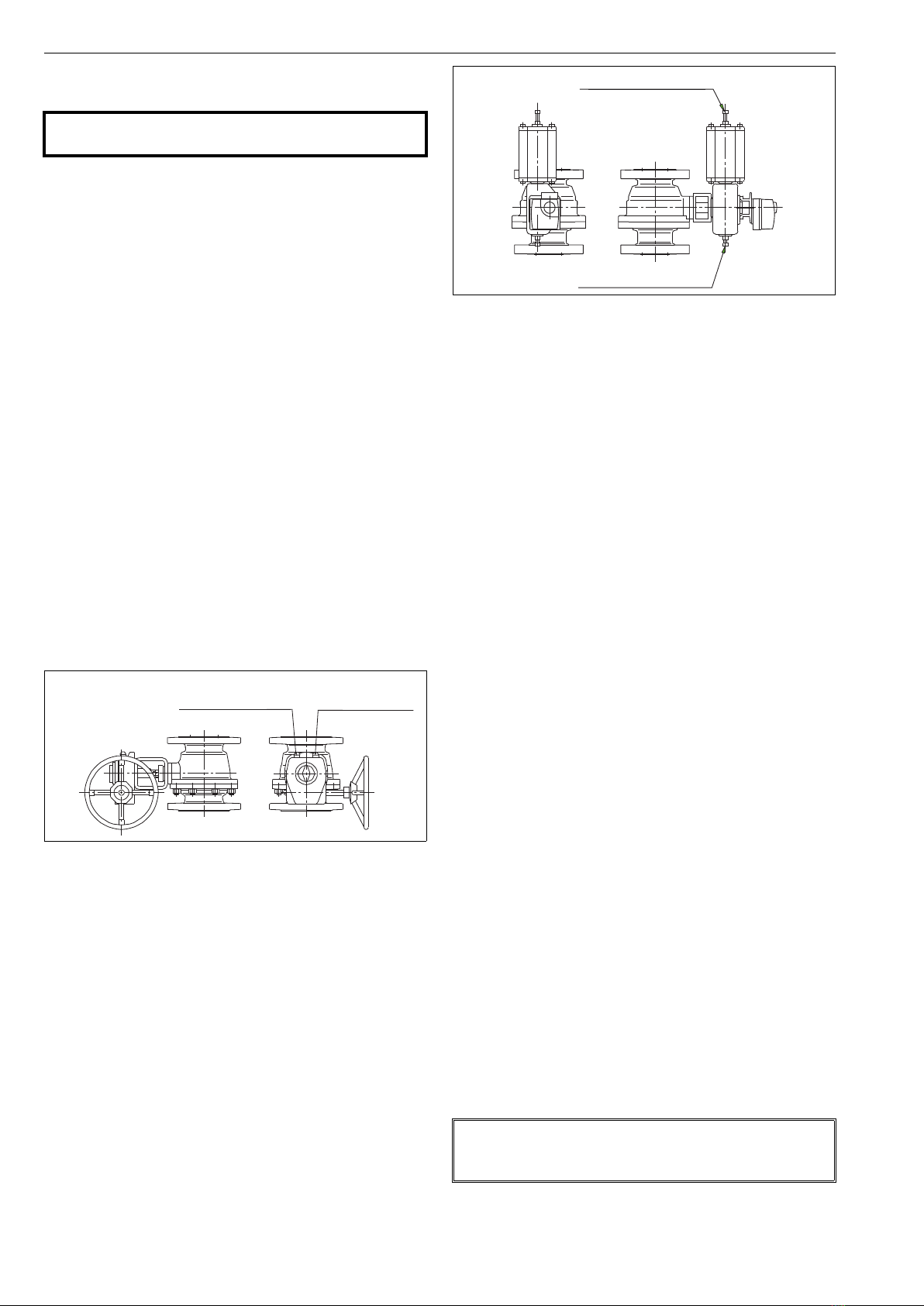
Adjust the ball open and closed positions with the
hexagon screws located at the side of the housing
(see Figure 16). The stop-screw for the open position
is nearest to the handwheel on the side of the hous-
ing and the screw for the closed position is at the
opposite end. The turning directions for the
handwheel are marked on the wheel.
Check the handwheel by turning the valve to the
extreme positions. The yellow arrow should indicate
the direction of the ball flow bore.
6.3 Installing the B1C-series actuator
Turn the valve to the closed position and drive actu-
ator piston to the extreme outward position.
File off any burrs and clean the shaft bore.
The line at the end of the shaft indicates the direction of
the ball flow bore.
Lubricate the actuator shaft bore. Fasten the bracket
loosely to the valve.
Slip the actuator carefully onto the valve shaft. Avoid
forcing it since this may damage the ball and seats.
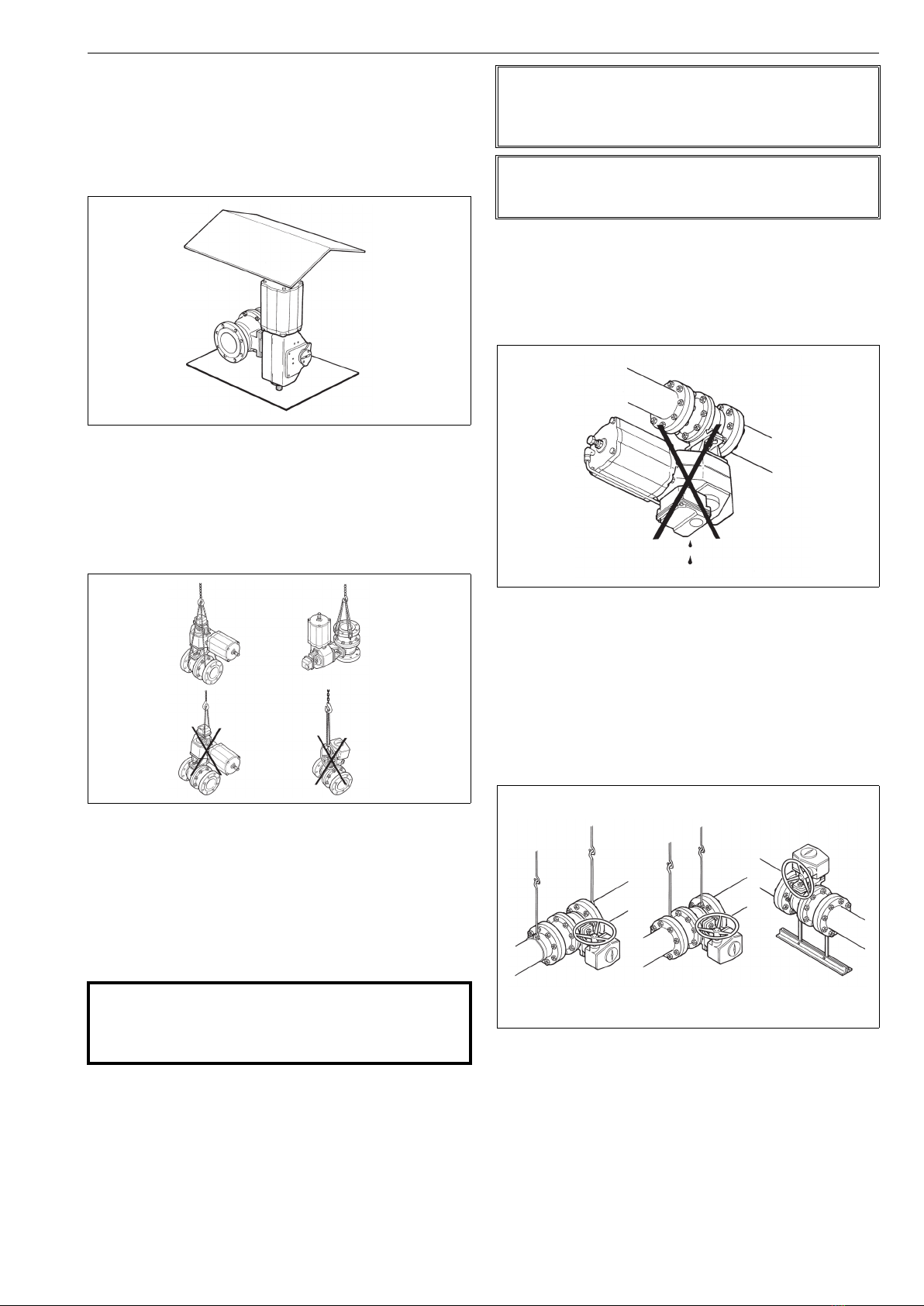
We recommend mounting the actuator so that the
cylinder is pointing upwards.
Position the actuator parallel or vertical to the pipe-
line as accurately as possible. Lubricate the actuator
mounting screws and then fasten all screws.
Adjust the ball open and closed positions by means of
the actuator stop screws located at both ends (see
Fig. 17). An accurate open position can be seen in the
body flow bore. Check that the yellow arrow on the
actuator indicates the ball flow opening position. Keep
fingers out of the flow bore!
There is no need for stop screw adjustment if the actuator is
re-installed in the same valve. Drive actuator piston to the
housing end (open position). Turn the actuator by hand
until the valve is in the open position. Fasten the actuator in
this position as explained above.
Check the stop screw thread tightness. An O-ring is
used for sealing.
Check that the actuator is functioning correctly. Drive
the actuator piston to both cylinder ends and check the
ball position and its movement with respect to the
actuator (close: clockwise; open: counterclockwise).
The valve should be closed when the piston is in the
extreme outward position.
If necessary, change the position of the actuator
pointing cover to correctly indicate the valve open/
closed position.
6.4 Installing the B1J-series actuator
Spring-return actuators are used in applications where
valve opening or closing movement is needed in case the air
supply is interrupted. The B1J type is used for spring-to-
close operation; the spring pushes the piston towards the
cylinder end, the extreme outward position. In turn, the
B1JA type is used for spring-to-open operation; the spring
pushes the piston towards the housing. Spring-return actu-
ators are installed in a manner similar to B1C-series actua-
tors, taking into account the following.
6.4.1 B1J type
Install the actuator so that the piston is in the
extreme outward position. The cylinder must not be
pressurized and air supply connections must be
open. The valve must be in the closed position.
6.4.2 B1JA type
Install the actuator so that the piston is in the cylinder
end position at housing side. The cylinder must not be
pressurized and air supply connections must be open.
The valve must be in the open position.
The rest of the installation procedure is the same as in Sec-
tion 6.3.
6.5 Installing other makes of actuators
Other actuators can be installed only if they have an
ISO 5211 actuator connection.
CAUTION:
Beware of ball cutting movement!
Fig. 14 Open and closed positions of the M actuator
stop-screw for stop-screw for
OPEN position
CLOSED position
Fig. 15 Open and closed positions of the B1C/B1J actuator
NOTE:
Metso accepts no responsibility for compatibility of actuators
not installed by Metso.
stop-screw for CLOSED position
stop-screw for OPEN position

1 XH 70 en 11
7 TROUBLE SHOOTING TABLE
The following Table 3 lists malfunctions that might occur
after prolonged use.
Table 3. Trouble shooting
8TOOLS
In addition to standard tools, the following special tools
might facilitate some phases of the work.
For removal of the actuator:
- extractor (ID-code table in actuator's IMO).
This tool can be ordered from the manufacturer. Always give
the valve type designation when ordering.
9ORDERINGSPAREPARTS
When ordering spare parts, always include the following
information:
type code, sales order number, serial number
number of the parts list, part number, name of the
part and quantity required
This information can be found from the identification plate
or documents.
Symptom Possible fault Recommended action
Leakage through a
closed valve
Wrong stop screw adjustment of the actuator Adjust the stop screw for closed position
Faulty zero setting of the positioner Adjust the positioner
Damaged seat Replace seat
Damaged closing member Replace the closing member
Closing member in a wrong position relative to the actuator Select the correct keyway in the actuator
Leakage through
body joint
Damaged gasket Replace the gasket
Loose body joint Tighten the nuts or screws
Irregular valve
movements
Actuator or positioner malfunction Check the operation of the actuator and
positioner
Process medium accumulated on the sealing surface Clean the sealing surfaces
Closing member or seat damaged Replace the closing member or seat
Crystallizing medium has entered the bearing spaces Flush the bearing spaces
Gland packing leaking Gland packing worn or damaged Replace the gland packing
Loose packing Tighten the packing nuts

12 1 XH 70 en
10 EXPLODED VIEW AND PARTS LIST
Spare part (Spare Part Set): Recommended soft parts, always needed for the repair. Delivered as a set.
Spare part category 2: Parts for replacing of the seat. Available also as a set.
Spare part category 3: Parts for replacing of the closing element.
Spares for the full overhaul: All parts from the categories 1, 2 and 3.
Item Qty Description Spare part category
1 1 Body
2 1 Bodycap
3 1 Ball 3
5 1 Shaft 3
7 1 or 2 Ball seat 2
8 1 Bonnet
9A 1 Gland
9B 1 Sleeve
10 1 Key 3
12 Stud
13 Stud
14 Stud
16 Hexagon nut
17 Hexagon nut
18 Hexagon nut
42 1 Retainer ring
62 1 or 2 Seat spring 2
63 1 or 2 O-ring (B,R) 1
1 or 2 Back seal (F) 1
64 1 or 2 Back-up ring (B,R) 1
65 1 Body gasket 1
66 1 Bonnet gasket 1
69 Packing ring 1
70 3 Thrust bearing 3
89 2 Trunnion plate
91 2 Thrust bearing 3
99 2 Trunnion bearing 3
129 1 or 2 Ring (B,R) 2
130 1 or 2 Backseal (B,R) 1
150 Disc spring set
150 18
130
129
16
62 2
65
64
3
89
91
99
63
12
1
13
70
10
5
66
8
17
69
42
9A
9B
14
70
62
129
130 64
7
91
89
99
7
63

1 XH 70 en 13
11 DIMENSIONS AND WEIGHTS
A1
A
P
øD
øB
øB1
N
M
øO
E
K
Key acc. to ANSI B17.1
Mounting face acc. to ISO 5211
NPS DN A A1 ØB ØB1 ØD E K M N O P Weight
[kg]
Weight
[kg] (with
bracket &
adapter)
"XHG
Class 900
Raised Face"
02 50 368 144 215 225 49 353 308 6.35 46 25 27,8 130 140
03 80 381 145 240 285 74 434 383 6,35 51 30 32,9 140 160
04 100 457 173 290 348 100 541 462 12,70 80 45 50,4 230 250
06 150 610 237 380 433 150 629 539 12,70 90 55 60,6 470 540
08 200 737 303 470 508 201 847 701 22,23 146 85 94,6 850 980
10 250 838 325 545 630 252 1045 866 25,40 180 105 116,1 1430 1640
12 300 965 389 610 728 303 1110 905 31,75 205 120 133,8 2150 2480
14 350 1029 416 640 804 322 1279 1054 31,75 225 135 149,0 2890 3340
16 400 1130 443 705 922 373 1401 1153 38,10 250 150 166,6 3950 4460
18 450 1219 504 785 1010 423 1474 1195 38,10 280 165 181,8 5020 5610
20 500 1321 549 855 1114 471 1508 1194 44,45 315 180 199,5 6530 7390
24 600 1549 643 1040 1300 570 1720 1350 50,80 370 220 242,4 11000 12000
"XHG
Class 900
Ring Type Joint"
02 50 371 145 215 225 49 353 308 6.35 46 25 27.8 130 140
03 80 384 146 240 285 74 434 383 6,35 51 30 32,9 140 160
04 100 460 175 290 348 100 541 462 12,70 80 45 50,4 230 250
06 150 613 239 380 433 150 629 539 12,70 90 55 60,6 470 540
08 200 740 304 470 508 201 847 701 22,23 146 85 94,6 850 980
10 250 841 327 545 630 252 1045 866 25,40 180 105 116,1 1430 1640
12 300 968 390 610 728 303 1110 905 31,75 205 120 133,8 2150 2480
14 350 1039 420 640 804 322 1279 1054 31,75 225 135 149,0 2890 3340
16 400 1140 448 705 922 373 1401 1153 38,10 250 150 166,6 3950 4460
18 450 1232 510 785 1010 423 1474 1195 38,10 280 165 181,8 5020 5610
20 500 1334 556 855 1114 471 1508 1194 44,45 315 180 199,5 6530 7390
24 600 1568 652 1040 1300 570 1720 1350 50,80 370 220 242,4 11000 12000

14 1 XH 70 en
12 TYPE CODE
*) Bolting material for stainless steel body
**) Bolting material for carbon and low alloy steel body
Note: Ball material coding specifies only the type of material not grade
(cast, wrought, bar, forged), which can change based on ball size or type.
E.g. "316SS" type may be A351 gr CF8M, A479 gr 316, A182 gr F316 or
equivalent.
Recommended type codings for oxygen service:
XH _ GW TZ S6 RR FR DD A
XH_ GW TZ N1 NR FE DD A
XH _ GW TZ VE LR FD DD A
Constructions are not covered in ISO 15848-1 certification.
Neles Trunnion Mounted, Ball Valve, Full Bore, Series XH
1. 2. 3. 4. 5. 6. 7. 8. 9. 10. 11. 12.
XH 06 G W TA AB RX R N B F A
1. VALVE SERIES & STYLE & FACE-TO-FACE
XH Full bore, trunnions, f-to-f ASME B 16.10, Table 4, long pattern,
ASME 900
2. SIZE / NPS
02 2"
03 3"
04 4"
06 6"
08 8"
10 10"
12 12"
14 14"
16 16"
3. PRESSURE CLASS
GASME Class 900
4. END CONNECTION STYLE
WRaised face, ASME B 16.5, (Ra 3.2-6.3), standard
ZRing joint, ASME B16.5
5. CONSTRUCTION & APPLICATION
TA Standard construction. Double seated. Live loaded packing.
TZ
BAM tested non-metallic materials, for oxygen service.
Double seated. Metal bearings.
Live loaded graphite packing.
Temperature range -50...+200C. Max pressure based on body
rating.
Oxygen cleaning acc. to Metso internal procedure T-2115
included.
Constructions are not covered in ISO 15848-1 certification
6. BODY MATERIAL
AB ASTM A350 LF2 (CS)
S6 ASTM A351 gr. CF8M (SS)
7. BALL / COATING & STEM MATERIAL
RX 316SS / Chrome carbide & XM-19 or 17-4PH
SL 316SS /NiBo & XM-19 or 17-4PH
8. SEAT TYPE
BMetal, solid proof
FMetal, bellows
RMetal, firesafe service
9. SEAT MATERIAL
NType 316 stainless steel
10. BEARING & SEAL MATERIAL
Trunnion
bearing Packings Body gaskets O-rings
BPTFE / SS net Graphite Graphite Viton GF
DCobalt based
alloy
Graphite Graphite Viton GF
11. BOLTING MATERIAL
Studs Nuts
D* B8M 8M
F** L7M 2HM
12. MODEL CODE
AXH design version A

1 XH 70 en 15

Metso Corporation
Töölönlahdenkatu 2, PO Box 1220, 00100 Helsinki, Finland
Tel. +358 20 484 100
http://contact.metso.com/
Neles Finland Inc.
Vanha Porvoontie 229, P.O. Box 304, FI-01301 Vantaa, Finland.
Tel. +358 20 483 150. Fax +358 20 483 151
www.metso.com/valves
16 1 XH 70 en
Table of contents
Other Mesto Control Unit manuals
Popular Control Unit manuals by other brands

Mitsubishi
Mitsubishi FX2N user manual

HP
HP HP 85091A reference guide

emaux
emaux FLEX Series Installation and operation manual

Bozzio
Bozzio Joysteer Generation 2.0 manual

ICI Caldaie
ICI Caldaie NEREIX Master INSTRUCTIONS FOR INSTALLATION AND ASSISTANCE

Metal Work
Metal Work Safe Air 70 series operating instructions

Honeywell Home
Honeywell Home V4043 installation instructions

Xytronix Research & Design
Xytronix Research & Design ControlByWeb X317 user manual

DAB
DAB ESY I/O Instruction for installation and maintenance

SMC Sierra Monitor
SMC Sierra Monitor Pure Humidifier ProtoAir FPA-W44 Startup guide

M-system
M-system TR3EX instruction manual

DOLD
DOLD SAFEMASTER BH 5928 Datasheet / Operating Instructions