Metagenics Fitness Smart Spin Bike User manual

Metagenics Fitness
Smart Spin Bike
!
!
!
!
!
!
Company Address:
4640 Caulfeild Drive, West Vancouver, British Columbia, V7W1E8 Canada
Company Name:
METAGENICS FITNESS INC.
www.metagenics.ca
Tel: 604-921-2098
Fax: 604-921-2386
Owner's!Manual!
!

Safe Use Instructions
WARNING: This manual contains important safety
information. Please read the safety instructions carefully before
using the machine.
uChildren and people with disabilities cannot access or use this device
when unsupervised.
uBefore training, please pay attention to the safety warnings and exercise
instructions on the equipment. If you feel unwell during exercise, please
stop training and consult a doctor immediately.
uIncorrect or over-training may damage your health.
uRegularly inspect and maintain the equipment, to ensure the integrity
and firmness of the various parts of the equipment.
uPay attention to the inspection and maintenance of vulnerable parts on
the device.
uIf the instrument parts are damaged or an abnormal sound occurs, stop
using it immediately until it is repaired.
uThe instrument should be installed in a stable place and leveled.
uBefore use, adjust the device according to your personal situation, such
as the size of the resistance, the position of the saddle, etc.
uMaximum user weight:350 lbs
uThe minimum space for this device: 3000x1200x2400mm (LxWxH)
uProduct parameters are as follows:
Model
Metagenics Fitness Smart Spin Bike
Connectable terminal
Smart phone, tablet
Software supported version
IOS、Android
Color
Black
Sensor system connection
Bluetooth
Resistance system
Magnetron resistance system
Drive Way
Belt drive
Power Voltage
Input:AC100-240V Output:DC 9V,1.5A
U
Rated maximum load
350 lbs
UL certified adapter

1、Plastic-absorbing tool plate!!!!!
!
Figure!1!
!
2、Bill of materials!
Seri
al
Numbe
r
Name
Quantit
y
A88
Semicircular head cross flower screw M5*12
4
A87
Pad Φ5
6
A14
Nylon mat S1151
2
A15
Spring Pad Φ5
2

A13
Semicircular head cross flower screw M5*16
2
A86
Cross flower self-tapping screws ST3.5*12
4
A1
Semicircular head inner hexagon screws M10*60
4
A2
Pad Φ10
4
A3
Spring Pad Φ10
4
A4
Self-locking nuts M10
4
B1
Inner hexagonal wrench(4mm)
1
B2
Inner hexagonal wrench(5mm)
1
B3
Inner hexagonal wrench(6mm)
1
B4
Inner hexagonal wrench(8mm)
1
B5
cross screwdriver
1
B6
10-13,15-17 open wrench
1
Assembly Steps
STEP1:
Please confirm the parts are complete first:
13!
!
!
!

NO.
Name
quantity
NO.
Name
quantity
1
frame
1
8
handle
adjustment
1
2
console
1
9
saddle
adjustment
1
3
bottle cage
1
10
pedal
2
4
saddle
1
11
console rear
cover support
1
5
front foot tube
1
12
Plastic-absorb
ing bag
2
6
rear foot tube
1
13
Adapter
1
7
handle
1
STEP2:
Use! semicircular head inner hexagon screws M10*60(A1)、pad Φ10(A2)、spring pad
Φ10(A3)、self-locking nuts M10 (A4) to fix front foot tube (5) and rear foot tube (6) on
the frame(1) ;!
!
!
!
STEP3:
Connect wire ends in handle adjustment tube(8) and frame(1), then insert handle
adjustment tube(8) into frame(1),and adjust to proper height ;

!!!!!!!!!!!! !
STEP4:
Connect exposed end of wire in STEP3 through console rear cover support (11) with
console(2), then use semicircular head cross flower screwM5*12(A88) and pad Φ5(A87)
to fix console(2) on the handle adjustment(8); and use flat countersunk head cross flower
self-taping screw ST3.5*12(A86) to fix console rear cover support (11) on the console(2),
and then use nylon mat S1151(A14), washerΦ5(A87), spring washerΦ5(A15),
semicircular head cross flower screw M5*16(A13) to fix bottle cage(3) on the handle
adjustment(8); and then adjust handle adjustment(8) to the following position, then use
flat countersunk head inner hexagon screw M8*16 (A10) (not in the plastic-absorbing
tool plate, already assembled with handle adjustment(8)) to fix handle(7)on the handle
adjustment(8); at last screw tightly pedal(10) on the crank.(please attention on left(L)
pedal and right(R) pedal and screw tightly both pedal screw clockwise)

!
!
STEP5:'
Insert saddle adjustment (9) into frame (1), and adjust to the proper height, and fix
saddle(4) on the saddle adjustment(9).
!!!!!!!!! !

Verification after Assembly
1) The joint parts are connected normally, and the adjustment handles are tightened
without looseness.
2) The handle assembly and the saddle assembly are securely fastened with no signs of
relative sloshing.
3)The pedals are fixed and there is no looseness.
4)The brakes are properly connected and used normally.
5)The movement is smooth without obvious abnormal sound during use.
Note: Please tighten the screw and nut before use to prevent loosening.

Instruction
1、Adjustment of the position of the handle and the saddle
Before exercise, adjust the position of the handle and the saddle as well as
display degree according to your height. Loosen the part when you turn the
adjustment handle counterclockwise and fix the part when you turn the
adjustment handle clockwise. The saddle and handle can be adjusted in the
direction shown in Figure 3.
!
!!!!!!!!!!!!!!!!!Figure!3!
1) Standing upright next to the bike, adjusting the bike saddle to the buttocks position. As
shown in Figure 4.
2) Adjust the height of the handle so that the lowest part of the handle is the same height
as the saddle. As shown in Figure 5.
3) Adjust the front and rear position of the saddle. When your foot is at the forefront,
your knee just exceeds your foot, as shown in Figure 6.
4) Adjust the handle, the distance between the saddle and the handle is equal to the
length of your forearm. As shown in Figure 7.
!!!!
Note: When adjusting the up and down position of the handle and
the seat, their highest position cannot exceed the horizontal
line "STOP" as shown in Figure 8.
2. Console angle adjustment methods
Figure!4!
Figure!5!
Figure!6!
Figure!7!
Figure8!
STOP

Use a 5mm wrench to loosen the two locking screws counterclockwise (turn
clockwise to lock, counterclockwise to loosen) as figure 9; adjust a proper console
angle and lock it down clockwise.
Figure 9
3、Tighten and loosen safe belt on pedal
1) Put your foot into the pedal and tighten the
safe belt upward to the right place as shown in
Figure 10.
2) When getting off the bike, firstly press the safety button, and then loosen safe belt
upwards as shown in Figure 11.
4、Precautions during training
To train in the right way. For example, when
riding a bicycle, it is forbidden to put your
hands in the air and at the same time stand upright for training as shown in figure 12.
'
'
'
'
'
'
'
'
Exploded'View'
Figure!10!
Figure!11!
Figure!12!

!!!!!!!!!
1
S300LSpinningBike
CompanyAddress:
YinheEconomicDevelopmentZone,NingjinCounty,ShandongProvince,China
CompanyName:
ShandongDahuziFittingEquipmentCo.,Ltd
Tel:(0086)534-5534588
(0086)534-5060988
Fax:(0086)534-5060988
Owner'sManual
Part'list'
'
Serial!No.!
Name!
Quantity!
Serial!No.!
Name!
Quantity!
A1!
Hexagon!socket!head!screws!
4!
A60!
magnet!
4!
A2!
Washer!
4!
A61!
Hexagon!socket!head!screws!
1!
A3!
Spring!washer!
4!
A62!
Non-slip!nut!
1!
A4!
Non-slip!nut!
4!
A63!
Hexagon!socket!head!screws!
4!
A5!
cushion!
4!
A65!
multi-ditch!belt!
1!
A6!
PU!wheel!
2!
A66!
spring!
1!
'
A7!
'
Ball!bearing!
'
4!
'
A67!
cylindrical!head!inner!
hexagonal!screw!
'
1!
A8!
washer!
2!
A68!
non-slip!nut!
1!

A9!
Non-slip!nut!
2!
A69!
sliding!reducer!
4!
'
A10!
Hexagon!socket!countersunk!head!
screws!
'
2!
'
A70!
'
pull-out!in!7!shape!
'
1!
'
A11!
Hexagon!socket!countersunk!head!
screws!
'
4!
'
A71!
'
pull-out!knob!
'
1!
A13!
Half-round!head!cross!screw!
2!
A72!
reducing!sleeve!
2!
A14!
nylon!ring!
2!
A76!
nozzle!a!
1!
A15!
spring!washer!
2!
A77!
nozzle!b!
1!
A16!
washer!
2!
A78!
saddle!lock!pad!
2!
'
A17!
'
Hexagon!socket!head!screws!
'
1!
'
A79!
semicircular!head!cross!
flower!screw!
'
4!
A18!
brake!shell!1!
1!
A80!
washer!
4!
A19!
brake!shell!1!
1!
A82!
speed!sensor!
1!
'
A20!
'
fastener!
'
1!
'
A85!
flat!countersunk!head!cross!
flower!self-tapping!screw!
'
4!
'
A21!
'
gear!parts!
'
1!
'
A86!
flat!countersunk!head!cross!
flower!self-tapping!screw!
'
4!
A22!
Handlebar!limit!
1!
A87!
washer!
4!
'
A23!
'
Handlebar!
'
1!
'
A88!
semicircular!head!cross!
flower!screw!
'
4!
'
A24!
'
spring!
'
2!
'
A89!
cylindrical!head!inner!
hexagon!screw!
'
1!
'
A25!
'
screw!
'
1!
'
A90!
semicircular!head!inner!
hexagonal!screw!
'
2!
A26!
Hexagon!socket!head!screws!
1!
A91!
non-slip!nut!
2!
'
A27!
'
left!shell!
'
1!
'
A92!
cylindrical!head!inner!
hexagonal!screw!
'
1!
'
A28!
'
right!shell!
'
1!
'
A93!
semicircular!head!inner!
hexagonal!screw!
'
1!
'
A29!
'
shell!dome!
'
2!
'
A94!
electronic!cables!motor!to!
monitor!
'
1!
A30!
Cross!head!tapping!screws!
7!
1!
frame!
1!
A31!
half-round!head!cross!screw!
2!
2!
console!
1!
'
A32!
hexagon!socket!screw!with!cylindrical!
head!
'
4!
'
3!
'
bottle!cage!
'
1!
A33!
pulley!
1!
4!
saddle!
1!
A34!
decorative!cover!1!
2!
5!
front!foot!set!
1!
A35!
decorative!cover!2!
2!
6!
rear!foot!set!
1!
A36!
decorative!cover!3!
2!
7!
handlebar!set!
1!
'
A37!
'
decorative!cover!4!
'
2!
'
8!
handlebar!adjustment!tube!
set!
'
1!
A38!
hexagon!socket!head!screw!
4!
9!
saddle!post!set!
1!

!
13!
A39!
pulley!
1!
10!
pedal!
1!
A40!
Hexagon!socket!head!screw!
8!
11!
console!base!
1!
A41!
spring!washer!
8!
13!
handlebar!slider!
1!
A45!
bearing!
2!
14!
U-shape!plate!
1!
A46!
wave!washer!
1!
15!
idler!tighten-up!set!
1!
A47!
C!ring!
1!
16!
short!sleeve!
1!
A48!
bearing!
2!
17!
crank!
2!
A49!
washer!
2!
18!
aluminium!decorative!shell!
2!
A50!
Non-slip!nut!
2!
19!
rear!axle!
1!
'
A51!
Hexagon!socket!countersunk!head!
screws!
'
4!
'
20!
'
saddle!plate!
'
1!
A52!
spring!washer!
2!
21!
flywheel!
1!
'
A53!
Hexagon!socket!countersunk!head!
screws!
'
2!
'
22!
'
magnet!fixing!plate!
'
2!
A54!
washer!
1!
23!
resistance!rotating!block!
1!
A55!
Non-slip!nut!
1!
24!
brake!lines!
2!
A56!
Non-slip!nut!
1!
25!
sliding!block!
2!
A57!
pulley!
1!
26!
main!wheel!axle!
1!
A58!
ball!bearing!
2!
27!
front!axle!
1!
A59!
Non-slip!nut!
1!
28!
knob!
2!
A95!
Motor!
1!
A96!
Adapter!
1!
!
Console operation instructions

!
14!
1.After the bike is powered the console will look like Figure 1. At this point to you can press START
to start pedaling and you can increase the magnetic resistance to challenge yourself. This is the quick
mode. When you want to stop, you have to press STOP first and then RESET for 5 seconds to erase
everything from the console so that the bike is ready to be used again.
Use the red emergency lever to stop the bike immediately if you need too.!
Figure 1
2. On the IDLE mode screen, press the MODE key to select sport mode, then press UP key to select
different programs The sequence of selection is P00 (manual mode)→P01~P10 (these are different
profiles of trails or programs to choose from→U1~U2( these are users you can
have)→H01~H03(these are heart rate programs to choose from→and WATTS (watts program to
choose).
3. If you select P00 MODE, press the MODE button to confirm the entry to the MANUAL function.
Press the START/STOP button to start ; or press the RESET button to return to IDLE MODE. If you
press MODE to confirm the setting, set AGE→WEIGHT→TIME→DIST→CAL in sequence, you
can cycle the setting. Press START button to start this manual program. The time, distance and calorie
parameters can be set at the same time. When the countdown is completed, the program ends. If the
TIME/DISE/CAL is not set, the data will be counted.
4. After pressing MODE, press UP to select P01 to P10 programs, when you find a program you like,
press MODE to confirm that PROGRAM function is the main function to enter. If you press MODE
to confirm the setting, set AGE→WEIGHT→TIME in sequence, which can be set cyclically. Press
START button to START the motion state after setting.
5. If you press UP and DOWN to select U1~U2 MODE, press MODE to confirm that the USER
function is the main function to enter. If no modification is made, the default value is the main
function. Press START/STOP to START directly. OR press RESET to return to IDLE MODE. If you
press MODE to confirm the setting, set AGE→WEIGHT→TIME→LEVEL in sequence, which can
be set cyclically. Press START button to START the motion state after setting.

!
15!
6. If you press UP and DOWN to select H01~H03, press MODE to confirm that HRC function is the
main function to enter. If no modification is made, the default value is the main function. Press
START/STOP to START directly. OR press RESET to return to IDLE MODE. If you press MODE to
confirm the setting, set AGE→WEIGHT→TIME→THR in sequence, which can be set cyclically.
After setting, press START button to START the motion state. No heartbeat signal can still start HRC
mode, DM flashing [ ?], if there is still no heartbeat signal input within 15 seconds, then drop
one LEVEL every 10 seconds until the LEVEL reaches the lowest and the program enters END
MODE. The start-up defaults to minimum LEVEL. When biking, press UP and DOWN keys to adjust
the target heartbeat.
7. If you press the UP and DOWN keys to select CONSTANT WATTS, press MODE to confirm the
entry to CONSTANT WATTS. If you do not modify the default value, press START/STOP to start;
or press RESET to return to IDLE MODE. If you press MODE to confirm the setting, set SEX →
AGE →WEIGHT →TIME →TARGET WATT in order, you can cycle the setting, press the
START button to set the motion state. This TARGET WATT function moves with a fixed WATT
value. The motion determines the load LEVEL based on the TARGET WATT value and the RPM.
8.RECOVER function
(1). After pressing the RECOVERY button during motion or pause/stop state/end of motion, first
enter the heartbeat detection for 10 seconds, the PULSE indicator lights up, the PULSE window
displays the user's current actual heartbeat, and the TIME window displays 0:10 countdown, 10
seconds. The heartbeat signal is not received within, the PULSE window displays 0, and BI returns to
the state before the RECOVERY mode.
(2). If there is a heartbeat within 10 seconds, execute the RECOVERY mode for one minute:
i. At this moment, only TIME and PULSE function work, other functions stop and cannot be
displayed.
ii. The TIME window displays "1:00" and starts counting down (if there is no button pressed
during the countdown period and the heartbeat is stable input), the PULSE window displays the actual
heartbeat value, and when the countdown reaches zero, it displays "FX" (X value is 1~6). After 10
seconds of display or pressing the RECOVERY button to return to the state before entering
RECOVERY mode with BIBI sound.
(3). RECOVERY has not received the heartbeat signal for 6 seconds in 1 minute, the PULSE window
displays 0, no result is displayed, and it returns directly to the state before entering RECOVERY
mode with BIBI sound.

!
16!
Connect'to'Zwift'
'
1. Where'to'get'Zwift'
Zwift has mobile and computer versions
0.1.Computer version
Windows:http://www.zwift.com/download/pc
MAC:http://www.zwift.com/download/mac
On PC and MAC, Zwift supports ANT+connection which our consoles does not support. Our console only
supports BLE connection to Zwift.
0.2.Mobile devices
Be noted: Our consoles only support BLE connection to Zwift. Please use Zwift mobile apps
on iOS or Andorid or 4K Apple TV.
GooglePlay:https://play.google.com/store/apps/details?id=com.zwift.zwiftgame
Appstore:https://itunes.apple.com/us/app/id1134655040?mt=8
AppleTV:http://izwift.com/2017/11/20/zwift-apple-tv-start/ OnlyAppleTVwith4Kversion
To use Zwift freely, you need to subscribe. The free trail is 25km per year.
2. Operation'Steps'-Mobile'Apps'
Before you start....
*You need to sign up at Zwift with your email. Zwift does not use FB nor Google sign up.
*Our console simulates as a outdoor bike accessory to connect to Zwift.
You need to follow our instructions do settings step by step.
If the console is computer controlled, the console will be viewed as bike trainer for Zwift. The
speed will accelerate per your resistance level. At the same pedal cadence, the higher
resistance level you are pedaling the equipment, the higher speed you are outputting.
3. Connect'to'Zwift'with'computer'controlled'consoles'
Power on the bike/console, and make sure the console BLE is advertising.
Launch Zwift app at your mobile device. Below images are using iPad as example.
Different mobile devices might have difference screens but the operation steps are identical.
Below image shows logged in at Zwift. Click the arrow to next step, connecting to our consoles.

!
17!
!
!
After picking up a user, Zwift will ask you to select devices to connect to. Please select POWER SOURCE as
circled in the below screen.
Zwift will show nearby compatible BLE devices.
To pair your phone or tablet via Bluetooth to Zwift select your bike-04668 and then press OK.

!
18!
!
!
Connection!successful!
Upon!connection,!you!shall!see!screen!like!below.!Power!source,!cadence!and!controllable.!
Make!sure!these!3!options!are!connected!in!green!check.!
!

!
19!
Click ride or training. If you click ride, the road you choose will select the resistance level. In training mode
you will be able to change the resistance on the console itself if you want too.
'
'
Start'Zwift'
'
'
Change'the'resistance'level'
Different from iConsole+app, the console will enable resistance level change at Zwift connection. You can
change resistance level by UP to increase or DOWN to decrease.
When connecting to Zwift, console’s LCD will display resistance levels. Once you change the resistance level,
the gear ratio changes, too. As a result, different resistance levels with the same cadence will output different
speeds.
Apple'TV'Connection'
Our console can also connect to 4K Apple TV. It is identical to mobile devices.

!
20!
Warranty card Metagenics Smart spin bike
Thank you for purchasing the intelligent Metagenics Fitness Smart Spin Bike. Thank you! We
will provide warranty service after seeing your proof of purchase according to the relevant
terms on the warranty card. Please keep this warranty card in good condition and show it at the
time of repair.
Part Ι: Warranty Description
Metagenics Fitness Smart Spin Bike
Frame: Lifetime.
Parts: 5 years.
Wearables: 2 years.
Electronics: 2 years.
Part II: Warranty does not apply;
No relevant purchase voucher or invoice
Malfunction or damage caused by improper use, misuse, abuse (Maximum user weight of 350
lbs), natural wear and improper maintenance, accident (fire, explosion) or natural disasters
(such as lightning, earthquakes, typhoons, etc.);
Repair; misassemble, misuse, collision, negligence, abuse, alteration by maintenance personnel
without authorization from our company;
Tear; alter labeling flow code and anti-counterfeiting logo;
Products or accessories are out of warranty period.
The sensor device and other accessories are faulty due to the customer's disassembly (or
assembled not by the company's certified after-sales personnel);
Product failure or damage caused by other non-product quality problems, such as product
damage caused by poor handling and transportation.
!
Product information
Product Model:
Product Name:
Color:
User profile
User name
Tel
Purchasing place
Living Address
Invoice number /online order
number
Purchasing date: Service order number
Maintenance Record
Maintenance Date
Table of contents
Other Metagenics Fitness Exercise Bike manuals
Popular Exercise Bike manuals by other brands
Sunny Health & Fitness
Sunny Health & Fitness PERFORMANCE INTERACTIVE Series user manual
MYXfitness
MYXfitness MYX II product manual
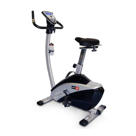
Bodyworx
Bodyworx A811 owner's manual

Sunny Health & Fitness
Sunny Health & Fitness SF-B020026 user manual

BH FITNESS
BH FITNESS YFAX90 Instructions for assembly and use

York Fitness
York Fitness espace owner's manual


