Damper shall be secured to sleeve and
to each other (when joined to make up
multiple damper assemblies) with #10
sheet metal screws 6" on center, 1/4"
diameter nuts and bolts, welding, 3/16"
steel pop rivets, or clinching (toggle)
See SECTION 2 and 3 for joint detail.
Angles shall be a minimum of 1-1/2" x 1-1/2" x 16 gauge. Fasten to sleeve with 1/4"
diameter nuts and bolts, welding 6" on center, #10 sheet metal screws 6" on center,
or 3/16" steel pop rivets. (See SECTION 4 for clearance and overlap).
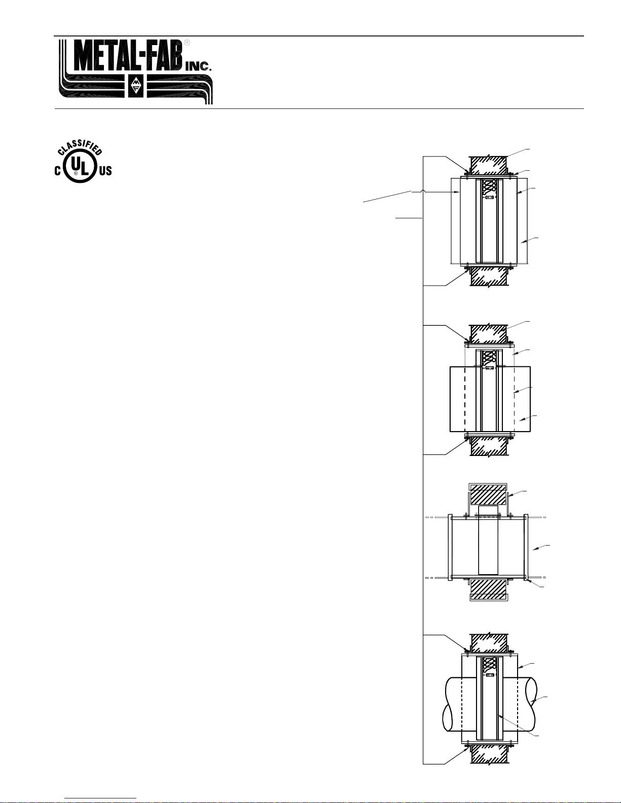
VERTICAL MOUNTINGS SHOWN - HORIZONTAL MOUNTING SIMILAR
1. SleevesshallbeoftheSAMEGAUGEorheavierastheducttowhichitisattached.
Gauges shall conform to SMACNA or ASHRAE duct standards. Sleeves shall
extend approximately 3" on either side of wall or oor to facilitate the joining of the sleeve
totheduct.Incaseswherethewidthoftheretainingangleissuchthatitwouldextend
approximately 2" beyond the edge of the angles see SECTION 3.
2A. The following duct-sleeve connections may be used on all systems:
• Inside slip • Angle slip
• Plain ‘S’ slip • Double ‘S’ slip
• Hemmed ‘S’ slip • Cup slip
• Bar slip • Drive slip
• Alternate bar slip (standing slip) • Pocket lock
• Reinforced bar slip (cleat)
Refer to separate “Breakaway Connection” sheet for further information.
2 B. Duct-sleeve connections may be of the rigid or xed type when re dampers are
installedinsleevesthatare16ga.upto36"Wx24"Hor14ga.forsizesexceeding36"
W x 24" H. For sleeves lighter than 16 GA. use breakaway connections.
3. Whentheductworkterminatesatthedamper,retaininganglesontheoppositesideof
theopening may bereversed providing thesize of theopening is increasedby an
amountequaltotwicethecombinedthicknessoftheangleandtheheightofthescrew
or bolthead to maintain expansion clearance (See SECTION 4). In this case the
sleeve at the open end may be made ush with the edge of the retaining angle.
4. Clearance between the sleeve and wall/oor opening shall be a minimum 1/8"
per foot on height and width of sleeve to a total maximum of 1-1/2" (e.g. damper
47-3/4" x 47-3/4", collar 48" x 48", opening 49-1/2" x 49-1/2"). Minimum clearance
shall be 1/4”. Perimeter angles shall overlap the wall/oor by a minimum of 1".
5. In cases where the openings are larger than the maximum multiple assembly
sizes specied in Note 5, a 12" wide brick or reinforced concrete mullion must be
provided between adjacent assemblies.
6. As with all joints, contractor must seal duct-collar connection, in eld, after
installation.
IMPORTANT
Do Not Cast Damper In Place.
Do Not Fasten Retaining Angles Or Damper Directly To Wall Or Floor.
Cycle Damper After Installation To Insure Free Movement
Do Not Install Damper Out Of Square Or Out Of Flat.
Install Damper In Plane Of Fire Separation.
*See separate instructions for re dampers in drywall.
*SPECIAL NOTE: When the damper or damper assemblies exceeds either 48" in
width or 60" in height, the retaining angles shall not be less than 1-1/2" x 1-1/2" x 1/8"
thick and shall be attached to the sleeve using 1/4-20 x 3/4" bolts at 8" on C. 1" long
welds or #14 x 3/4" sheet metal screws at the same spacing.
INSTALLATION INSTRUCTIONS FOR
MFD, MFD3, MDFD, MDFD3, MFDS, MFDS3, MFDUS, MFDUS3,
MDFDS AND MDFDS3
FIRE AND CEILING RADIATION DAMPERS
UL CLASSIFIED
(SEE COMPLETE
MARKING ON PRODUCT)
TYPE-A
VERTICAL MOUNTING WALL
SLEEVE
DUCT
BREAKAWAY
JOINT
DUCT
TYPE-B
VERTICAL MOUNTING WALL
SLEEVE
DUCT
BREAKAWAY
JOINT
DUCT
TYPE-C
VERTICAL MOUNTING
EXTENDED
MOUNTING
ANGLES
DUCT
DUCT
BREAKAWAY
JOINT
SLEEVE
DUCT
DUCT
BREAKAWAY
JOINT
ALTERNATE INSTALLATION
*SEE SPECIAL NOTE


