Metal-Fach Z562 User manual
1
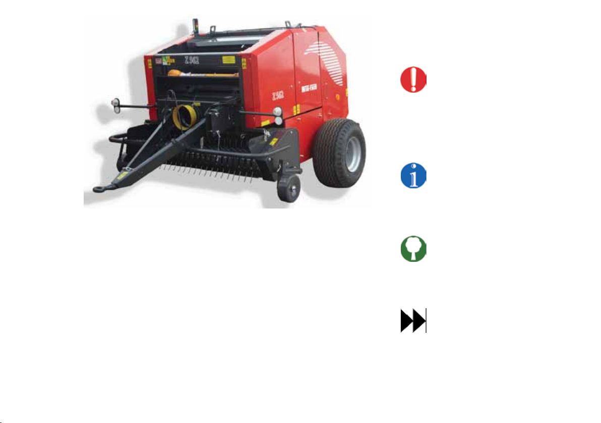
Thank you for choosing our Z562 baling press designed
for efficient operation.
The following manual will let you fully use the
advantages of our baling press and to optimise the bale
wrapping process.
The Manual contains a detailed table of contents
followed by descriptions which will allow to easily
identify the device and to make the best use of it.
The information regarding safety and comfort of
operation, description of coupling with a tractor,
technical service activities and storage conditions are
listed on the following pages of the manual.
A spare parts catalogue containing the list of the baling
press major components allowing for easy ordering
is attached to the Manual in a digital form on a CD.
A printed version of the catalogue can be purchased
at authorised service outlets or directly from the
manufacturer.
Both the manual and the spare parts catalogue contain
basic information on the product. The elements fitted to
the equipment may be slightly different than presented
in the manual.
The manufacturer reserves the right to introduce
changes without notice.
Legend
Warning:
This is a warning symbol and it indicates
that it is required to pay special attention
to the operator and bystanders'
safety requirements or safe operation
requirements.
Information:
This symbol indicates additional
information which allows to optimise
the device operation.
Environmental protection:
This symbol indicates the need to pay
special attention to environmental
considerations.
Cross-reference:
this symbol directs you to a page on
which detailed information on a given
subject is presented.

2
Table of contents
1 Baling press identification, general safety rules 3
1.1 Baling press identification 3
1.2 Z652 baling press construction 5
1.3 Z562 baling press characteristics 6
1.4 Z562 baling press dimensions 8
1.5 Location of symbols 9
1.6 Warning Symbols 12
1.7 General safety rules 13
2 Drive operation 15
2.1 Drive coupling 15
2.2 Disconnecting from the drive 17
3 Commissioning 17
4 Controls and ongoing adjustments 19
4.1 Location of the controls 19
4.2 Location of ongoing adjustment points 21
5 Baling press operation 29
5.1 Wrapping assembly 29
5.2 Hydraulic system 31
5.2.1 Standard hydraulic system 31
5.2.2 Optional hydraulic system 33
5.3 Electrical system 34
5.4 LP02 counter 35
5.4.1 LP02 counter system 35
5.4.2 Counter symbols 35
5.4.3 Connecting and commissioning of the counter 36
5.4.4 Counter operation 36
5.5 Wrapping 38
5.6 Finishing work 41
6 Periodical inspection 41
6.1 User inspection 41
6.2 Service checks 41
7 Authorised service 42
7.1 Warranty service 42
7.2 Ongoing maintenance 42
7.3 Ordering of spare parts 42
8 Press Transport 42
8.1 Transporting a load 42
8.2 Driving on public roads 43
9 Baling press storage 44
10 Hazards 45
10.1 Description of residual risks 45
10.2 Assessment of residual risks 45
11 Baling press disposal 46
12 Typical problems and troubleshooting 46
13 Accessories 47
14 Names and abbreviations 47
Warranty card 48
3
1 Baling press identication, general safety rules
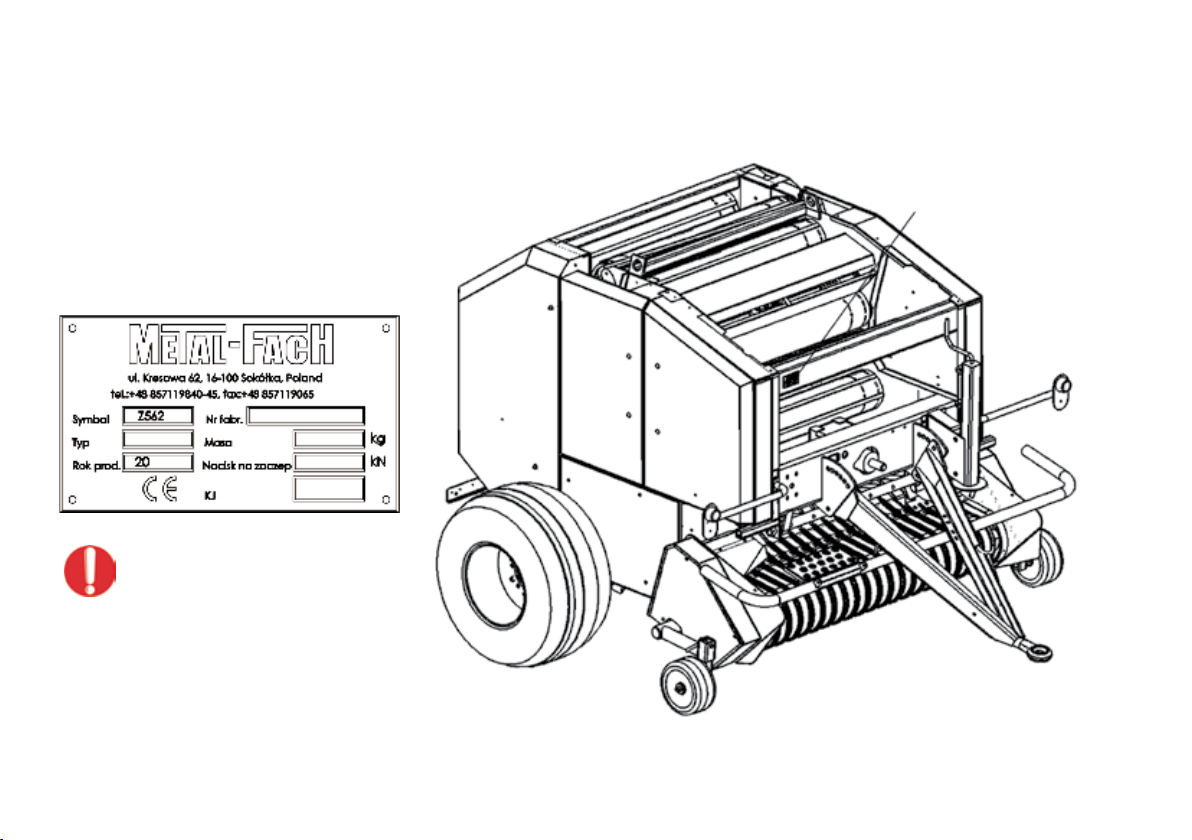
1.1 Baling press identication
The baling press is identified by its nameplate securely
fastened to the front guard of the machine.
The information presented on the nameplate is shown
on the diagram below.
Dziękujemy za wybór naszej owijarki bel Z237
zaprojektowanej do efektywnej pracy.
Niniejsza instrukcja obsługi pomoże Państwu
w pełni wykorzystać zalety owijarki i jednocześ-
nie zoptymalizować proces owijania bel.
Instrukcja zawiera szczegółowy spis treści a po
nim opisy ułatwiające identyfikację i poznanie
owijarki.
Informacje na temat bezpieczeństwa i komfortu
pracy, opis agregowania z ciągnikiem, pracy,
czynności serwisowych i warunków magazynowa-
nia znajdują się na kolejnych stronach instrukcji.
Katalog części zamiennych zawierający wykaz
podstawowych części owijarki ułatwiający ich
zamawianie dołączony jest do niniejszej instruk-
cji w formie elektronicznej na płycie CD.
Katalog w formie papierowej możecie Państwo
nabyć w autoryzowanych punktach sprzedaży,
lub bezpośrednio u producenta.
Zarówno instrukcja obsługi jak i katalog części
zamiennych zawierają podstawowe informacje
o wyrobie. Poziom wykończenia i kompletacji
wyrobu może nieznacznie odbiegać od przedsta-
wionego w opracowaniu.
Producent zastrzega sobie prawo wprowadzania
zmian konstrukcyjnych bez uprzedzenia.
Legenda
Ostrzeżenie:
symbol ten ostrzega i wskazuje
na konieczność bezwzględnego
przestrzegania wymogów
bezpieczeństwa operatora, osób
postronnych, lub bezpiecznej
pracy wyrobu.
Informacja:
symbol ten wskazuje dodatkowe
informacje pozwalające optyma-
lizować pracę wyrobu.
Ochrona środowiska:
symbol ten zwraca uwagę na
konieczność zachowania wymo-
gów ochrony środowiska.
Odsyłacz:
symbol ten odsyła Państwa do
strony, na której umieszczono
szczegółowe informacje na dany
temat.
1
It is forbidden to drive the baling press
on public roads without its nameplate or
with an illegible nameplate.
When purchasing the machine check the serial number indicated in the Manual and the warranty sheet against the
serial number stamped on the nameplate.
Data plate

4
The manual consist a part of the Z562
baling press's equipment.
If the machine is sold to another user, it must be
supplied with the operating manual. It is advised that
the supplier has a confirmation stating that the manual
was transferred together with the machine, signed by
the buyer and filed.
Carefully read the operating
manual.
If the rules stated in this manual are complied with,
it will help prevent hazards and operate the machine
efficiently; it will also allow to retain the warranty
throughout the period granted by the manufacturer.
Detailed information on the structure, operating
principles,technologyandotherdetailsmaybeobtained
from authorised outlets and the press manufacturer.
It is forbidden for persons who have not
read the manual to operate the baling
press.
The baling press shall be operated according to its
intended use by coupling it with a tractor with the
nominal power exceeding 30-70 kW and towing power
class of at least 0.9 - 1.4 (depending on the variant),
equipped with a PTO (with six keys) and allowing for the
external use of the hydraulic power system.
The Z562 baling press is designed for gathering of
material raked into embankments into bales: hay
(humidity up to 20%) and silage (humidity up to 60%)
and post harvest straw and unloading the rolled bales
on the ground.
During operation, the operator is not subject to noise
which may cause the loss of hearing, as the noise level of
the machine does not exceed 70 dB (A) and the operator
works inside the tractor cabin.
During the operation of the baling press, the operator
is not subject to harmful vibration as the vibration level
transferred to the upper limbs does not exceed 2.5 m/
s2, and the vibration level transferred to the body is
lower than 0.5 m/s2and the operator is positioned in the
tractor's cabin.
Continuous and systematic care for control
and adjustment elements and compliance
with the machine‘s maintenance schedule
will ensure optimum and long operating
life.
The manufacturer recommends to clean
the following daily: net/cord wrapping
assembly, rolling shafts and the drive
(chains, sprocket wheels, bearing
housings).
Any unauthorised changes to the baling
press structureabsolvethe manufacturer
from all responsibility for the threats and
damage it may cause.
Grass and other papilionaceous plants prepared for
souring and wrapping should be mowed in the early
phase of heading (best done in the afternoon). On
the next day, after a few hours of drying, the mowed
materialshouldbegathered usingthewrapping presses.
Maximum bale compression must be maintained.
5
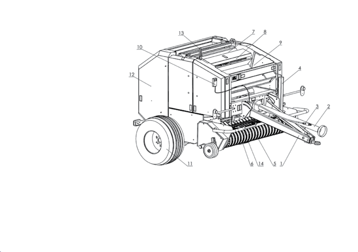
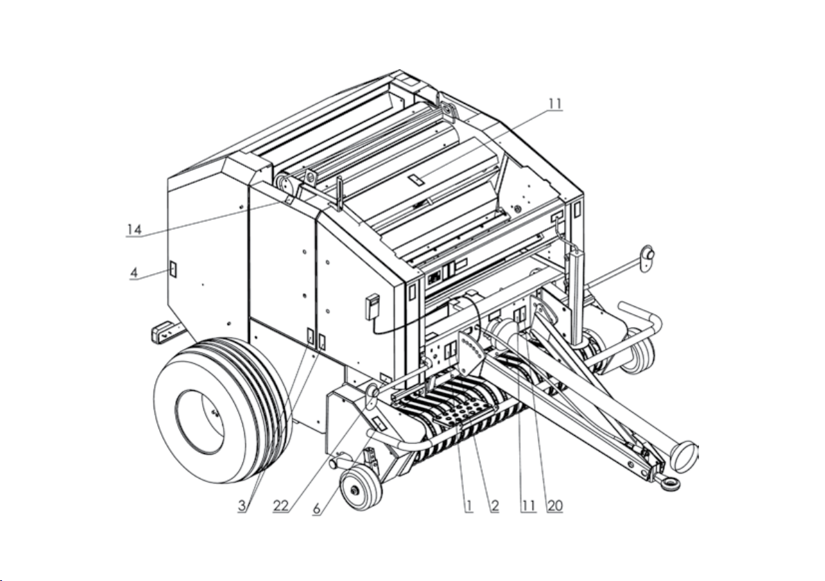
1.2 Z652 baling press construction
The Z562 baling press consists of the following units:
• Drawbar item 1
• PTO shaft item 2
• Hydraulic lines item 3
• Support foot item 4
• Pickup item 5
• Collector item 6
• Rolling shaft item 7
• Cord wrapper item 8
• Net wrapper item 9
• Control panel item 10
• Driving wheel item 11
• Cover item 12
• Indicator item 13
• Clamp item 14
In the front part of the press a pickup (5) is located, used to collect the swath formed into embankments. It works with a collector (6) directing the collected swath to the rolling
shafts (7) where it is pressed and rolled. The swath collection process and the bale unloading are presented on a diagram on the next page. When the desired compression
level is obtained it is indicated by the position of the indicator (13) in the red field and a sound signal located in the operator's cabin. When the programmed compression level
is obtained, the wrapper (8) wraps the bale with cord. When using a net, the wrapping is started manually from the control panel after the mentioned sound signal is heard.
The press is coupled to the tractor using the tow bar (1), the PTO shaft (2) and the hydraulic line (3). The support foot (4) is used to support the machine at rest and to couple and
uncouple the machine. The press is equipped with driving wheels (11) used for towing the machine behind the tractor.

6
1.3 Z562 baling press characteristics
No. Details Units Z562-0... Z562-1... Z562-2...
1. 2. 3. 4. 5. 6.
1. Press type –hitched
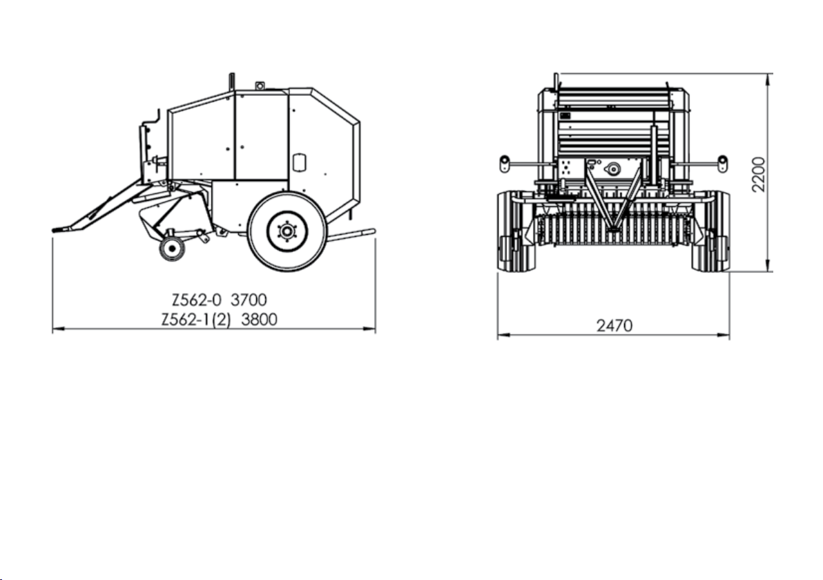
2. Overall dimensions: length/width/height mm 3730/2470/2050 3800/2470/2050 3800/2470/2050
3. Weight kg 2200 2300 2400
4. Operating/transport speed km/h up to 10 / up to 20
5. Minimum tractor power output kW 35 50 70
6. Required tractor hydraulic system pressure Atm./MPa 140/14
7. PIC power demand kW approx. 25 approx. 40 approx. 60
8. PTO rotational speed RPM 540
9. Hitch load kN 4.0
10. Operating personnel – 1 (tractor driver)
11. Rolled bale dimensions (diameter x width) mm 1200x1200
12. Bale weight kg 100-600
13. Production efficiency bales/h max. 20 max. 40 max. 40
14. Harvested bank width mm up to 1600
15. Undercarriage type –mono-axial
16. Tyres –400/60 - 15.5 14 PR
17. Tyre pressure kPa 350
18. Drawbar hitch-ring diameter mm 44
19. Coupling with a tractor - through – the lower hitch

7
No. Details Units Z562-0... Z562-1... Z562-2...
20. Pickup type – drum-pin, 4 beams
21. Pickup width mm 1800
22. No. of pickup pins pcs 44
23. Rolling assembly – chamber type –cylindrical, constant displacement
24. Rolling assembly – rolling mechanism – automatic wrapping with a single cord
optional – net wrapping
25. Rolling assembly – cord wrapping spacing adjustment –4 increments
26. Telescopic jointed shaft type/brand LFMR S.A. Lublin
27. Telescopic jointed shaft symbol C-60970, designated with
the KRUS Safety Mark
28. Telescopic jointed shaft product no. 6R-602-7-BA-K601
29. PTO drive-shaft – rated torque: 540 kN 540
30. PTO drive-shaft – nominal transmitted power kW 30
31. PTO – minimum shaft length mm 1010
32. PTO – operating speed RPM 540
33. PTO – coupling/clutch type –K601/1600 Nm w/shear pin
34. Electrical system voltage V12
35. Light system – acc. to the Traffic Code
8
1.4 Z562 baling press dimensions
The drawings show the dimensions of the baling press in the working position (in mm).
9
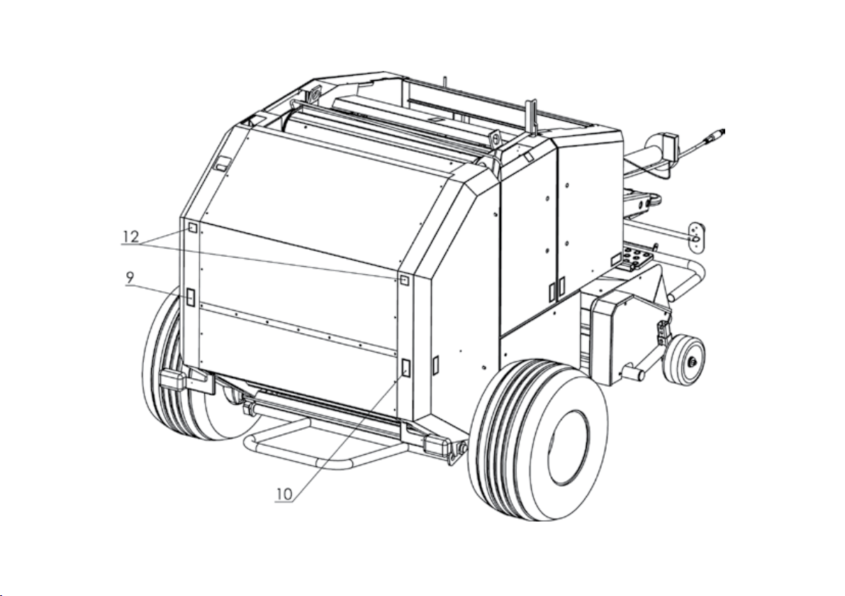
1.5 Location of symbols
Location of symbols - right
The meaning of symbols is explained in Section 1.6 of the Manual.

10
Location of symbols - le
The meaning of symbols is explained in Section 1.6 of the Manual.
11
Location of symbols - rear
The meaning of symbols is explained in Section 1.6 of the Manual.

12
1.6 Warning Symbols
Warningsymbolson themachine ( Section 1.5) inform
the operator about the hazards and dangers which may
occur during the machine operation. Keep the symbols
clean and legible.
Replace illegible symbols with new ones.
New symbols can be purchased from the
manufacturer.
Symbol 1
Refer to the operating manual before
performing this action.
Symbol 2
Turn off the engine and remove the
ignition key before servicing or repairs.
Symbol 3
Do not open or remove the safety
guards during machine operation.
Symbol 4
Keep a safe distance from the raising
guards during machine operation.
Symbol 5
Secure the lifting cylinder before
entering into the hazard zone.
Symbol 6
Do not reach into the pickup zone
while the tractor engine and PTO are
operating.
Symbol 7
Do not approach the working strands
during the baling press' operation.
Symbol 8
Do not approach movable, articulated
connections while the engine is
running.
Symbol 9
Do not stand below the raised cover
which is not protected against dropping
down.
Symbol 10
Crushing hazard - caused by the rolling
bale. Keep a safe distance from the
working machine.
Symbol 11
Do not open or remove the safety
guards during machine operation.
Symbol 12
Keep a safe distance from the
working machine.
Symbol 13
Main lubrication points of the
baling press.
Symbol 14
Lifting sling fixing point.

13
Symbol 15
Information symbol.
Symbol 16
Information symbol.
Symbol 17
Attention!
While turning around and while
negotiating sharp corners
disconnect the tractor's PTO drive.
Information symbol.
Symbol 18
Information symbol.
Symbol 19
Information symbol.
Symbol 20
Do not approach the rotating PIC shaft.
Symbol 21
Do not stand on ladders and platforms
while the tractor is moving.
Symbol 22
Information symbol.
1.7 General safety rules
1.7.1 During operation and repair of the Z562 baling
press the farming health and safety regulations
contained in the Regulation of the Minister of
Agriculture and Food Economy of 12 January 1998 must
be complied with.
1.7.2 Only an adult with a valid agricultural tractor
driver's licence and familiarised with the occupational
health and safety regulations regarding agricultural
equipment and this Manual may operate this machine.
1.7.3 The following manual must be read and adhered
to, paying special attention to directions regarding the
safe operation of the baling press.
1.7.4 The manual indicates the machine parts which
pose a potential threat. Hazardous areas are marked
with yellow stickers with warning symbols. Pay special
attention to the hazardous areas and strictly adhere to
the rules.
1.7.5 The operator must familiarise themselves with the
meaning of the symbols.
1.7.6 It is forbidden to operate the baling press without
the safety guards installed on moving components.
1.7.7 Every time before the the baling press is started,
check the condition and completeness of the machine
and positioning of its safety guards.
MAX 540 RPM
3.5 bar
NOTE!
THE MACHINE MAY ONLY BE STARTED
AFTER ALL COVERS ARE CLOSED

14
1.7.8 Before starting the baling press and entering
public roads, inspect the attachment of the machine
to the tractor, attachment of the wheels and proper
connection of the drawbar to the tractor.
1.7.9 All adjustment, repair and maintenance works
shall be conducted with the tractor engine turned off
and making sure that the machine is secured against
accidental start.
1.7.10 Before commencing swath collection and during
this process, make sure that there are no bystanders,
especially children, nearby.
1.7.11 During the operation of the baling press, allow
for free space near the rotating elements. During bale
rolling, no people or animals are allowed near the
rotating elements.
1.7.12 Exercise extreme caution when working on an
inclined land. Note that the bales may roll down slopes.
1.7.13 It is forbidden to operate the baling press with
any of the assemblies lifted.
1.7.14 Do not remain between the baling press and the
tractor when the tractor engine is running.
1.7.15 Exercise extreme caution when coupling/
decoupling the press with/from the tractor. The
machine should be coupled with the tractor equipped
with a lower hitch able to withstand the vertical load
larger than the vertical load exerted on the baling press
drawbar. Section 1.3.
1.7.16 During operation, use appropriate protective
clothing and shoes with anti-slip soles.
1.7.17 While loading the wrapping cord or net, the
tractor engine must be turned off and protected against
accidental activation (ignition key removed, parking
brake on).
1.7.18 It is forbidden to operate damaged hydraulic
lines. The damaged lines must be immediately replaced
with new ones. During the replacement of hydraulic
lines, use impermeable protective clothing.
1.7.19 The machine hydraulic system shall only be
operated from the tractor cabin.
1.7.20 Before driving the machine check the position of
the support foot. The support foot should be placed in a
transport position.
1.7.21 Follow the traffic code regulations and the
manufacturer's recommendations when travelling on
public roads. Section 8.2.
1.7.22 Before entering public roads, perform a visual
inspection of the transported machine.
1.7.23 It is forbidden to stand on the press during
machine operation or transport.
1.7.24 While travelling on public roads, it is forbidden
to transport swath or silage bales in the press chamber.
1.7.25 It is forbidden to operate the baling press while
under influence of alcohol.
1.7.26 It is forbidden to operate the baling press while
under influence of drugs or medicines with similar
effects.
1.7.27 It is forbidden to operate the machine while
under influence of medicines which affect the ability to
drive vehicles or reduce psychophysical fitness or cause
concentration disorders and increase reaction time.
1.7.28 It is forbidden to drive the baling press near
sources of open flame.
1.7.29 It is required to strictly adhere to the fire
protection regulations and immediately extinguish any
fire which may occur during the baling press use or at
its standstill.
1.7.30 Do not approach the working baling press with
open flame and do not smoke near the machine.
15
1.7.31 Every time before commencing work, check if the
tractor is equipped with a dry powder extinguisher. If
not, place a dry powder fire extinguisher on the tractor.
2 Drive operation
2.1 Drive coupling
The baling press should be coupled with agricultural tractors
of the rated power not lower than 35 - 70kW and towing
power class 0.9 - 1.4, equipped with two hydraulic system
connections, a rear PTO shaft with six keys and the nominal
of RPM 540.
The baling press shall be coupled to the lower hitch allowing
for the maximum vertical load of 4.0 kN.
Coupling the machine to the tractor's
lower hitch.
Make sure that there are no bystanders,
especially children, in the coupling area.
Before coupling the equipment, place
the tractor axis in the machine axis on
a hard, flat, level surface. Turn off the
tractor engine, remove the ignition key
and engage the tractor parking brake.
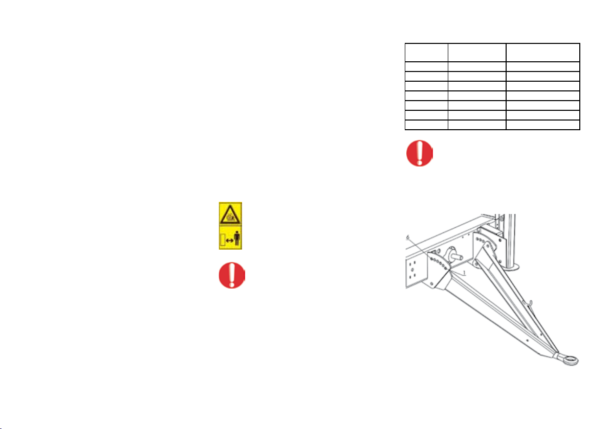
Set the appropriate hitch height by
selecting the proper adjustment lug as
shown on the diagram.
The height of the drawbar above the ground is given in the
table below.
Slot no. Units Height of the tow bar above
the ground
123
Slot no. 1 cm 15.50
Slot no. 2 cm 31.00
Slot no. 3 cm 46.50
Slot no. 4 cm 63.00
Slot no. 5 cm 78.50
Slot no. 6 cm 94.00
Couple the hitch-ring with the lower
hitch and check whether the machine is
properly connected and secured against
accidental disconnection.
16
Only couple the machine to tractors with
weight appropriate for the machine.
Make sure that the tractor hydraulic
system is tight.
Connect the electric power source. Check if the electric and
signalling systems work properly.
Connect the hydraulic power source. Check if the hydraulic
systems work properly, especially the baling press door
opening and closing mechanism.
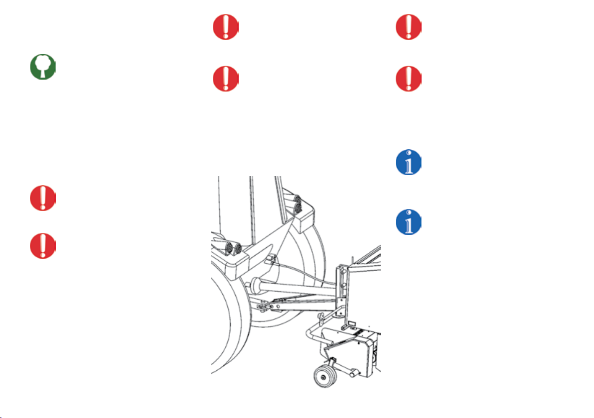
Coupling the press with the rear PTO
Before connecting the telescopic jointed
shaft check the direction and speed of
shaft revolutions.
Turn off the tractor engine, remove the
ignition key and engage the tractor
parking brake. Slide the outer socket of
the telescopic jointed shaft on the six
notch rear PTO. Place the second outer
socket on the press' PIC until the locks
snap in place. Install the shaft cover
chains on both sides of the shaft.
It is forbidden to use telescopic jointed
shafts with parameters other than
specified by the manufacturer.
It is strictly forbidden to use a telescopic
jointed shaft with its guards missing or
damaged and without the additional
cone guards at the tractor PTO and the
machine PIC sides.
Shortening or extending the telescopic
jointed shafts may only be performed at
specialist service stations.
Every time the telescopic jointed shaft
is coupled and every time the machine
is put into operation it is required to
make sure that the shaft condition is
undamaged and the protection pipe and
cone are properly attached.
If the safety bolts of the telescopic
jointed shaft overload clutch are
sheared, replace them with new bolts
with the same technical parameters.
The manufacturer suggest to use the
machine in straight line runs. It is
advised to turn off the drive while the
machine is negotiating sharp corners
and during transport.

17
2.2 Disconnecting from
the drive
Make sure that there are no bystanders,
especially children, in the baling press
storage area and its vicinity.
Place the baling press for storage on a hard, flat and
level ground. Turn off the tractor engine, remove the
ignition key and engage the tractor parking brake.
Disconnect the electric power supply.
Disconnect the hydraulic system.
Lower the main frame support. Disconnect the hitch-
ring from the tractor hitch. Make sure that the machine
will not move accidentally.
Disconnect and dismantle the telescopic
jointed shaft. Place the shaft on the
support designed for its storage. Protect
the PTO and telescopic jointed shaft
couplings with covers.
3 Commissioning
The commissioning of a newly purchased
baling press should be performed by
a dealer's service representative or a
manufacturer's representative in the
presence of the operator - owner of the
machine.
Before commissioning the baling
press, familiarise yourself with the this
manual, paying special attention to the
fragments regarding the safety of the
operator and bystanders.
If there are any doubts regarding
safety issues, please contact your sales
representative or the manufacturer.
Before each start up of the baling press, the LP02
counter shall be installed in the tractor operator's cabin.
Section 5.4.3.
Commissioning the baling press
Take extra caution during
commissioning.
The presence ofpersons undertraining in
the machine's operation zone increases
the safety hazard.
During the commissioning of a newly purchased
baling press a dealer's service representative or a
manufacturer's representative in the presence of the
operator - owner of the machine performs the following
actions:
3.1 Control of press operation and equipment:
3.1.1. Completeness and technical condition check,
3.1.2. Sound signal device and lighting equipment
functional test,
3.1.3. Functional test of the hydraulic system:
- lifting and lowering of the pickups,
- lifting and lowering of the rear chamber,
- lifting and lowering of the shredder blades
(optional equipment)
3.1.4. Rear chamber lock engagement and locking test,
3.1.5. Functional test of the pickup,
3.1.6. Functional test of the wrapping mechanism:
- test with cord,
- test with net (optional supply).
3.1.7. Functional test of the central lubrication system
(optional supply),
3.1.8. Functional test of the ensilage applicator (optional
supply).

18
3.2. User training in proper operation of the press:
3.2.1 Review of the pickup design and principles of
operation:
- adjustment of spring attack angle,
- overload clutch functions,
- clutch installation after the bolts are sheared,
- replacement of the complete overload clutch,
- lubrication of the roller raceways.
3.2.2 Review of the cord wrapping mechanism design
and principles of operation:
- review of the principle of operation,
- installation of the cord,
- adjustment of the wrap spacing and cord tension,
- adjustment of the bale compression ratio,
- cleaning the cord feeder.
3.2.3 Review of the net wrapping mechanism design
and principles of operation (optional supply):
- review of the principle of operation,
- installing the net,
- adjusting the wrap number,
- adjusting the spring tension for the blade
support bracket.
3.2.4 Review of the central lubrication system design
and principles of operation (optional supply):
- review of the principle of operation,
- adjustment of the (dosing) pump delivery.
3.2.5 Review of the ensilage applicator design and
principles of operation (optional supply):
- review of the principle of operation,
- start up and dosing adjustment.
3.2.6 Review of the rotor and the shredder design and
principles of operation (optional supply):
- review of the principle of operation of the rotor,
- review of the principle of operation of the
shredder,
- disassembly, blade sharpening and assembly.
3.2.7 Review of the LP02 counter design and principles
of operation
3.2.8 Review of the principles of operation of the
tractor-baling press unit during baling:
- tractor operation during swath collection along
a straight line,
- tractor operation during swath collection along
curves and sharp bends,
- explanation of hazards.
3.2.9 Performing the full bale wrapping with cord +
net by the user under supervision of the service
technician
3.2.10 Review and adjustment of the chain tension
3.2.11 Review of the lubrication procedures and ongoing
maintenance of the press
3.2.12 Review of user questions and remarks.
The commissioning is performed by the
service without any additional charges.
The service technicain's signature on the warranty
card confirms that the commissioning process was
performed as described in this section. The customer's
signature confirms that the commissioning of the baling
press was performed in the presence of the buyer/user.
19
4 Controls and ongoing adjustments
4.1 Location of the controls
Hydraulic system controls
The baling press hydraulic system is controlled using the tractor's control levers.
The control levers are used to adjust the pickup position and opening and closing of
the baling chamber. Section 5.2 Hydraulic system
Press control using the counter
For operation and control of press operation the manufacturer supplied the electronic
LP02 counter with baling press control functions and information functions.
Before starting the baling press, the LP02 counter shall be installed in
the tractor operator's cabin. Section 5.4.3.
Description of baling press control using the counter Section 5.4
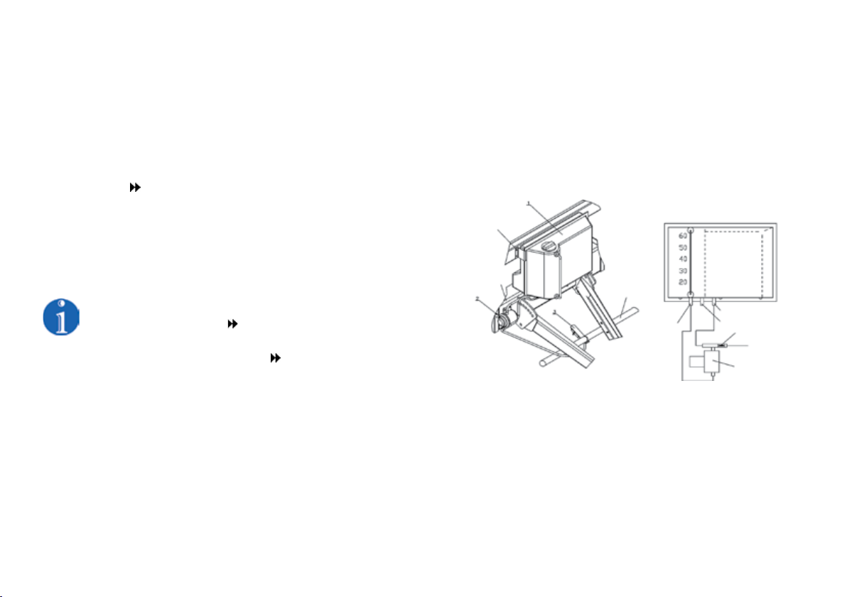
Ensilage application
The ensilage applicator is offered by the manufacturer as separately purchased
optional supply.
The applicator is used for precise dosing of liquid ensilage preparation facilitating the
silage forming process.
The applicator is located in a location indicated in the diagram below. If the applicator
is purchased separately at a later date the user may install it on his own (checking
if the purchased equipment is not missing any parts) or at an authorised reseller or
manufacturer.
The applicator consists of the following parts:
- 60 litre tank,
- filler with filtering insert,
- 2 connector pipes,
- drain valve;
- cut-off valve;
- spreading nozzles rated at:
350 ml/min,
600 ml/min,
1000 ml/min,
Metal brackets
Diagram for the installation of the
pump and spraying nozzles
Crossbeam
Pickup pipe
Return stub pipe
Drain valve
Cut-off valve
Pump
Spraying nozzle hose
Inlet stub pipe

20
- inlet hose Ø10 mm, length L=70 cm - 1 pc.
- return hose Ø10 mm, length L=70 cm - 1 pc.
- pressure conduit Ø12 mm, length L=110 cm - 1 pc.
- 12 V electric pump.
Begin the installation of the applicator by installing the pump (item 2) on the crossbar,
in a place indicated in the diagram. Then, using M8x30 blots and M8 nuts install the
60 litre tank (item 1). Install the spraying nozzles (item 3) on the pickup pipe. This
will allow the dosing of the preparation at the entire width of the harvested material
between the machine pickup and the rolling chamber. Connect the inlet hose, return
hose and pressure conduit as indicated on the diagram.
Using the plug connect the applicator's power supply to the press electric system.
The press is equipped with a socket dedicated for the applicator power supply. It is
located under the front cover on the right side of the press.
Turning the press on/off is performed by pressing the on/off button on the counter.
For preparing silage the manufacturer suggests using biological
preparations or preparations containing effective microorganisms.
Before starting the pump fill the tank with liquid. Prepare the liquid as specified by the
ensilage preparation manufacturer.
Pour the properly mixed preparation through the filtering insert in the tank inlet.
When the tank is full, fully open the stub pipe and switch on the pump using the ON
button on the counter. The pump will start sending liquid to the nozzles. The spraying
of the material with ensilage begins.
Depending on the collected swath use nozzles with appropriate flow rate:
- deflector nozzle in white body – output 1000 ml/min;
- deflector nozzle in red body – output 600 ml/min;
- deflector nozzle, w/o body – 350 ml/min.
Do not start the pump if the tank is empty. The pump may be destroyed
after a period of "dry running".
When the work is nished ush the applicator and ltering insert. Remove all remains
of the preparation and all mechanical remains. Remove all residues from the tank
through the drain valve.
Other manuals for Z562
2
Table of contents
Other Metal-Fach Farm Equipment manuals


Popular Farm Equipment manuals by other brands

Schaffert
Schaffert Rebounder Mounting instructions

Stocks AG
Stocks AG Fan Jet Pro Plus 65 Original Operating Manual and parts list

Cumberland
Cumberland Integra Feed-Link Installation and operation manual

BROWN
BROWN BDHP-1250 Owner's/operator's manual

Molon
Molon BCS operating instructions

Vaderstad
Vaderstad Rapid Series instructions


