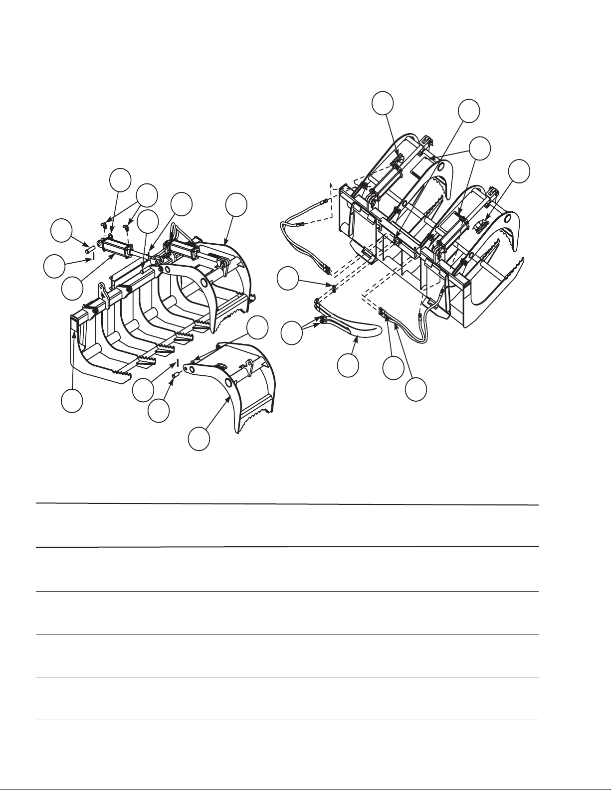
2-7741 2-7748
2-7742 2-7749
2-7743 2-7750
Page 4 of 6F-4315 1-20-10
ATTACHING BRUSH GRAPPLE TO
LOADER BOOM
No tools are needed to install quick attach
brush grapple. Loader must be equipped
with skid steer quick attach male coupler.
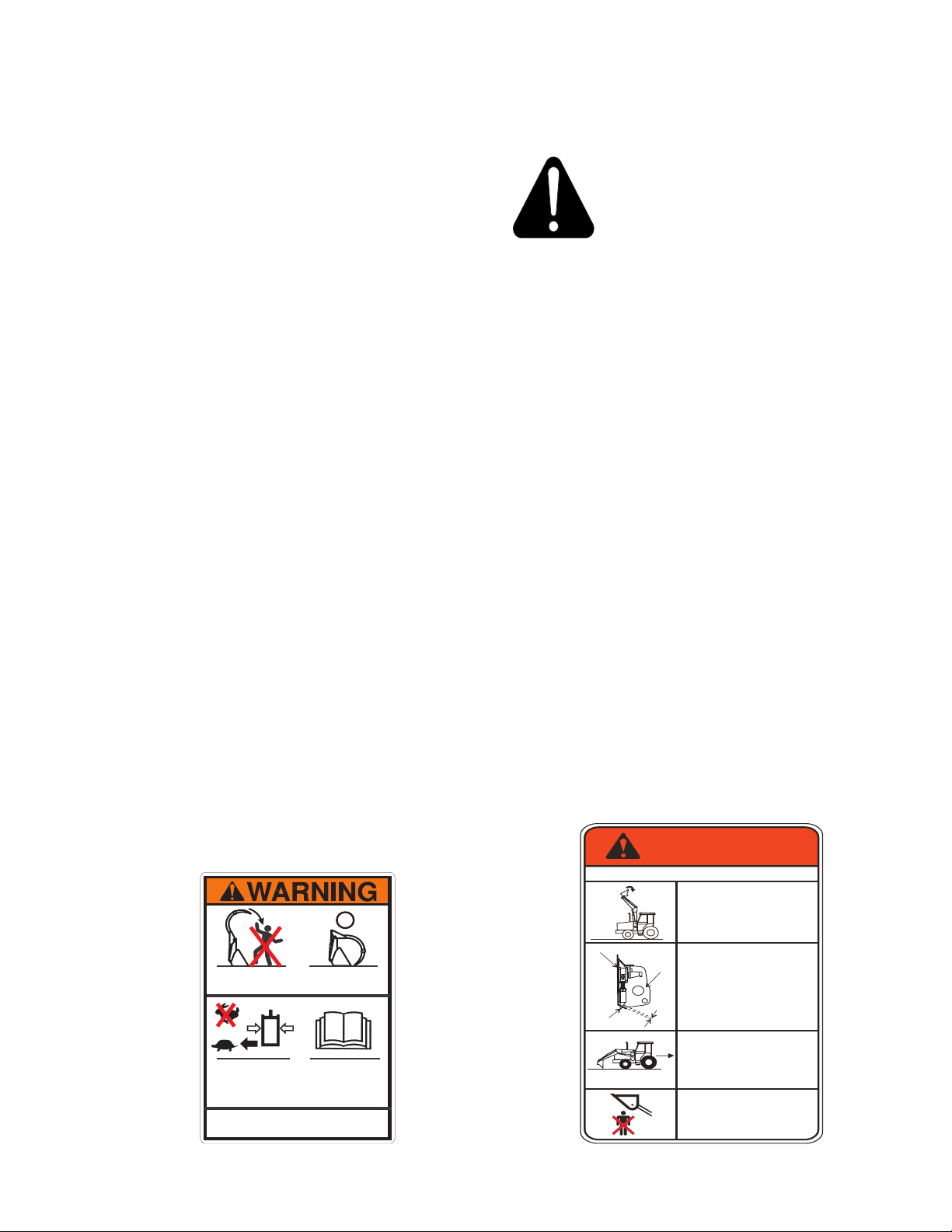
WARNING: To avoid injury during
attachment or detachment, do not
allow bystanders within 10 feet of
loader or attachment.
1. Remove attachment from loader and store
properly.
2. Locate tractor and brush grapple on level
ground. Lower boom to rest on ground.
Extend the bucket cylinders slightly, while
raising the boom to provide 3 to 5” of
ground clearance. Drive the tractor forward
slowly toward the brush grapple, aligning
the loader quick attach device.
3. While driving the tractor ahead slowly to
maintain contact with the brush grapple,
activate the lift cylinders to raise the loader
boom until the male quick attack engages
the female attachment lip.
4. Activate the bucket cylinders to retract,
continuing to roll the brush grapple back
completely.
5. Place tractor in neutral, set parking brake,
and shut off tractor. Rotate the quick
attach latch handles down in engage the
latch pins.
6. Start tractor and raise brush grapple 1
to 2 feet off ground and extend bucket
cylinders to tilt brush grapple at a slight
downward angle, so quick attach latch
pins are visible. Visually inspect the brush
grapple to verify the pins are engaged
through the latch plate on the back of the
brush grapple.
NOTE: If the brush grapple is not securely
attached, follow the instructions for
detaching it and repeat the above
procedure.
7. Lower loader boom to ground, place
tractor in neutral, set parking brake, and
shut off tractor. Move valve joystick to
relieve hydraulic pressure in all lines.
Connect brush grapple hydraulic hoses to
auxiliary hydraulic source (rear remotes,
3rd function kit) to operate the claws. Set
hydraulic speed control to “slow” for claw
operation.
8. Start tractor and cycle the grapple claws
a number of times to purge air from
cylinders. Check tractor hydraulic reservoir
and replenish with tractor manufactures
recommended hydraulic uid.
OPERATING BRUSH GRAPPLE
Operation of your tractor and loader with brush
grapple attachment requires additional consid-
erations from bucket operation. You now have
to operate the brush grapple while already op-
erating the tractor and loader. You need to also
take into account additional space require-
ments (added length and height) needed be-
cause of attached brush grapple.
GRASPING BRUSH
o Approach the pile with claw open and
bottom level. Use loader boom oat
position, if material is on the ground.
o Ease valve control lever for grapple claw
forward to close grapple claw around
material pile.