Metal Work FLUX 0 User manual

FLUX 0
DIGITAL FLOWMETER AND PRESSURE SENSOR
USER MANUAL

2

3
@2019 KITA Sensor Tech. Co., LTD. URL hiip://www.kita.com.tw
-1-
KFP01 Series Instruction Manual
Product Safety Instructions
■
This section indicate the levels of risks with the labels of Danger, Warning and Caution.
Danger indicates high level of risk, will lead to fatal or serious injuries if not
avoided.
Warning indicates medium level of risk, it might cause death or serious injuries.
Caution indicates low level of risk, it might result in minor injuries, such as scald,
electric shock, etc. and the product, equipment and machines might be damaged.
Danger
Warning
Warning
Caution
■
Precautions for use
Operated within the specified voltage.
Malfunction or damaged product, electric shock or fire may
be resulted by exceeding the specified voltage range.
Do not exceed the maximum load current.
It may damage the product.
Do not use any load that generates surges.
Surge protection is present but applying surge voltage
repeatedly will ultimately damage the product.
When using with inductive load (such as relay or solenoid),
please install a flyback diode across the load (polarity must
be observed).
Observed the internal voltage drop.
When used at a specified voltage, if the sensor is functional
but the load does not work, please check if the operating
voltage of the load meets the following formula.
Power Supply – Internal voltage > Minimum operating
voltage drop of sensor voltage of load
Do not operate the product outside the specifications.
The sensor will be damaged by exceeding the flow rate and
working pressure.
Do not use flammable fluids and/or permeable fluids.
They may cause fire, explosion or corrosion.
➀
➁
➂
➃
➄
➅
■Working fluid and working environment
Do not use in an explosive gas atmosphere.
The sensor does not have explosion-proof structure, fire,
explosion or corrosion can result.
Do not use near a surge voltage generated area.
Solenoid lifters, high frequency induction furnaces and
motors, etc. can generate high surge voltages, if using near
the sensor will cause the internal circuit components to
deteriorate and cause damages.
Sensors can not withstand lightning strikes.
The product is CE compliant, but can not resist surge
voltage of lightning strikes, take measures to avoid
lightening strikes in the system.
Do not use in an environment where sensors could
be splashed by water or oil.
Enclosure rating is IP40, please avoid water or oil splashed
environment to prevent adversely effects.
Do not use in an environment subject to large
temperature cycling.
Internal components of the sensor will be affected adversely
by large heating/cooling cycles other than ordinary changes
in temperature.
Do not mount the product in locations where it is
exposed to radiant heat.
This could result in damage and/or malfunction.
➀
➁
➂
➃
➄
➅

4
@2019 KITA Sensor Tech. Co., LTD. URL hiip://www.kita.com.tw
-2-
KFP01 Series Instruction Manual
■Installation Precautions
Ensure the flow direction of the fluid.
Please follow the flow direction indicator for installation and
piping.
Flush out all dirt and dust by air blow before connect
the piping to the sensor.
Do not drop or hit.
When installation, do not drop, hit or apply excessive shock
(100m/s2). Internal damage can cause malfunction even if
the housing appears to be undamaged.
Do not install multiple products in close proximity.
The heat generated from each product could cause the
temperature to rise and change the characteristics of
product or deterioration of the plastic parts. Please set the
products 10mm apart from each other.
Hold the sensor body when installing.
The tensile strength of the cable is 24.5 N and apply
excessive pulling force can cause damage to the sensor.
➀
➁
➂
➃
➄
■Other Precautions
After power is supplied, the output will remain off until
the display is turned on. Please operate the sensor
after the value is shown.
Stop the control systems before perform setting
changes.
During the initial flow and pressure setting, the product will
switch the output according to the existing settings until the
changes are complete.
➀
➁
■Installation Precautions
Please follow the specified tightening torque.
Over tighten will damage the product.
Do not mount the sensor in a place that will be used
as a foothold.
The product may damage if sit or step on it accidentally.
When mounting without a bracket, please use P type
self-tapping screw- M3 x L 6mm.
Do not remove the fixed pin for the One-Touch Fitting.
To avoid losing the internal parts and cause malfunction.
➀
➁
➂
➃
■Maintenance Precautions
The accuracy could change by 2 to 3% when the
piping is removed or replaced.
Do not insert a stick or wire into the piping ports.
Do not touch the terminals or connectors when power
is on.
➀
➁
➂
■Wiring Precautions
Check wire color and terminal number when wiring.
Incorrect wiring can cause permanent damages to the
sensor, check wire color and terminal number against the
manual before wiring.
Avoid repeatedly bending or stretching the lead wire.
It can cause damage to the sheath, or breakage of the
wire.
Confirm wiring insulation
Please avoid poor insulations (and interference from
another circuit, poor insulation between terminals, etc.) it
can lead to over current being applied to the product,
causing damage.
Do not route wires and cables together with power or
high voltage cables.
The product may malfunction due to interference or noise
and surge voltage from power and high voltage cables.
Do not short-circuit the load.
When the load is short-circuited, an error will be displayed.
But excess current may cause damage to the sensor.
Do not connect wire when the power is on.
It may cause damages to the sensors/equipment/machines.
➀
➁
➂
➃
➄
➅
Warning
Caution

5
KFP01 Series Instruction Manual
@2019 KITA Sensor Tech. Co., LTD. URL hiip://www.kita.com.tw
-3-
■
Fluid
Disclaimer
Check the regulator and flow adjustment valve before
introducing the fluid.
If the pressure or flow rate exceeded the specified range,
the sensing element may be damaged.
Recommended Equipments and Installation
Recommended Equipments and Installation Example
Our warranty applies solely to our product, not to any other damages and injuries which occur by earthquakes,
fires, the acts by third party, other matters, acts intentionally, acts accidentally, misuse, or other abnormal conditions
that are not the responsible of KITA.
Our warranty applies solely to our product, not to any other additional damages (the loses of business profits,
business interruption, etc.) incurred due to using or misusing the product.
Our warranty excludes any injuries and damages happened by using the product beyond the specified range of
catalog or/and not following the instruction manual.
➀
The sensing element cannot measure properly if
foreign matter adheres to it.
On the inlet side, be sure to install an air filter below
the filtration level of 10um.
➁
➂
➃
➀
➂
➁
➄
KFP01 Series
Pressure Sensor
Flow Sensor
Or
Flow Sensor
KFP01 Series
Pressure Sensor
Or
Air Source
Filter
Regulator
Micro Mist Separator
(Oil Mist Filiter)
Air Dryer
KFP01 Series
Flow Sensor
Pressure Sensor
※NOTE:
When measuring the pressure of the inlet side, install a throttle valve or solenoid valve on the outlet side.
When measuring the pressure of the outlet side, install a throttle valve or solenoid valve on the inlet side.
Inlet
Outlet
Air Source
Filter
Regulator
Micro Mist Separator
(Oil Mist Filiter)
Air Dryer
Inlet
Outlet
Throttle Valve
※NOTE:When measuring the pressure of the inlet side, install a throttle valve or solenoid valve on the outlet side.
※NOTE:When measuring the pressure of the outlet side, install a throttle valve or solenoid valve on the inlet side.
Air Source
Filter
Regulator
Micro Mist Separator
(Oil Mist Filiter)
Air Dryer
Throttle
Valve
Inlet
Outlet
Warning

6

7
INDEX
1. INSTALLATION PAGE 8
1.1 PIPING PAGE 8
1.2 MOUNTING BRACKET / OPTIONAL PARTS PAGE 9
1.3 WIRING DIAGRAMS PAGE 10
1.3.1 PNP Output, analog output and external input PAGE 10
2. HOW TO USE PAGE 11
2.1 NAMES AND FUNCTIONSOF INDIVIDUAL PARTS PAGE 11
2.2 FUNCTION INSTRUCTION PAGE 12
2.3 OPERATION INSTRUCTIONS PAGE 13
2.3.1 [F-01] OUT1 Setting selection PAGE 14
2.3.2 [F-02] OUT2 Setting selection PAGE 19
2.3.3 [F-03] LCD Display color selection PAGE 20
2.3.4 [F-04] Response time selection PAGE 21
2.3.5 [F-05] Display refresh time selection PAGE 23
2.3.6 [F-06] Unit selection PAGE 25
2.3.7 [F-07] Flow reference standard selection PAGE 26
2.3.8 [F-08] Analog output selection PAGE 27
2.3.9 [F-09] Accumulated value hold selection PAGE 28
2.3.10 [F-10] Flow sensor display mode selection PAGE 29
2.3.11 [F-91] Power-save mode selection PAGE 30
2.3.12 [F-92] External input selection PAGE 31
2.3.13 [F-94] Fine adjustment setting PAGE 32
2.3.14 [F-95] Forced output function PAGE 34
2.3.15 [F-99] Reset to the default setting PAGE 35
2.3.16 Pressure zero adjustment function PAGE 36
2.3.17 Instantaneous flow zero adjustment function PAGE 37
2.3.18 Reset accumulated flow function PAGE 38
2.3.19 Peak value display PAGE 39
2.3.20 Bottom value display PAGE 40
2.3.21 Key lock / unlock mode PAGE 41
3. ERROR CODE INSTRUCTION PAGE 42
4. TECHNICAL DATA PAGE 43
5. THERMAL MASS FLOW SENSOR PRINCIPLES PAGE 44
6. DIMENSIONS PAGE 45
7. CONSTRUCTION PAGE 45
8
1. INSTALLATION
@2019 KITA Sensor Tech. Co., LTD. URL hiip://www.kita.com.tw
-5-
Installation
KFP01 Series Instruction Manual
1Installation
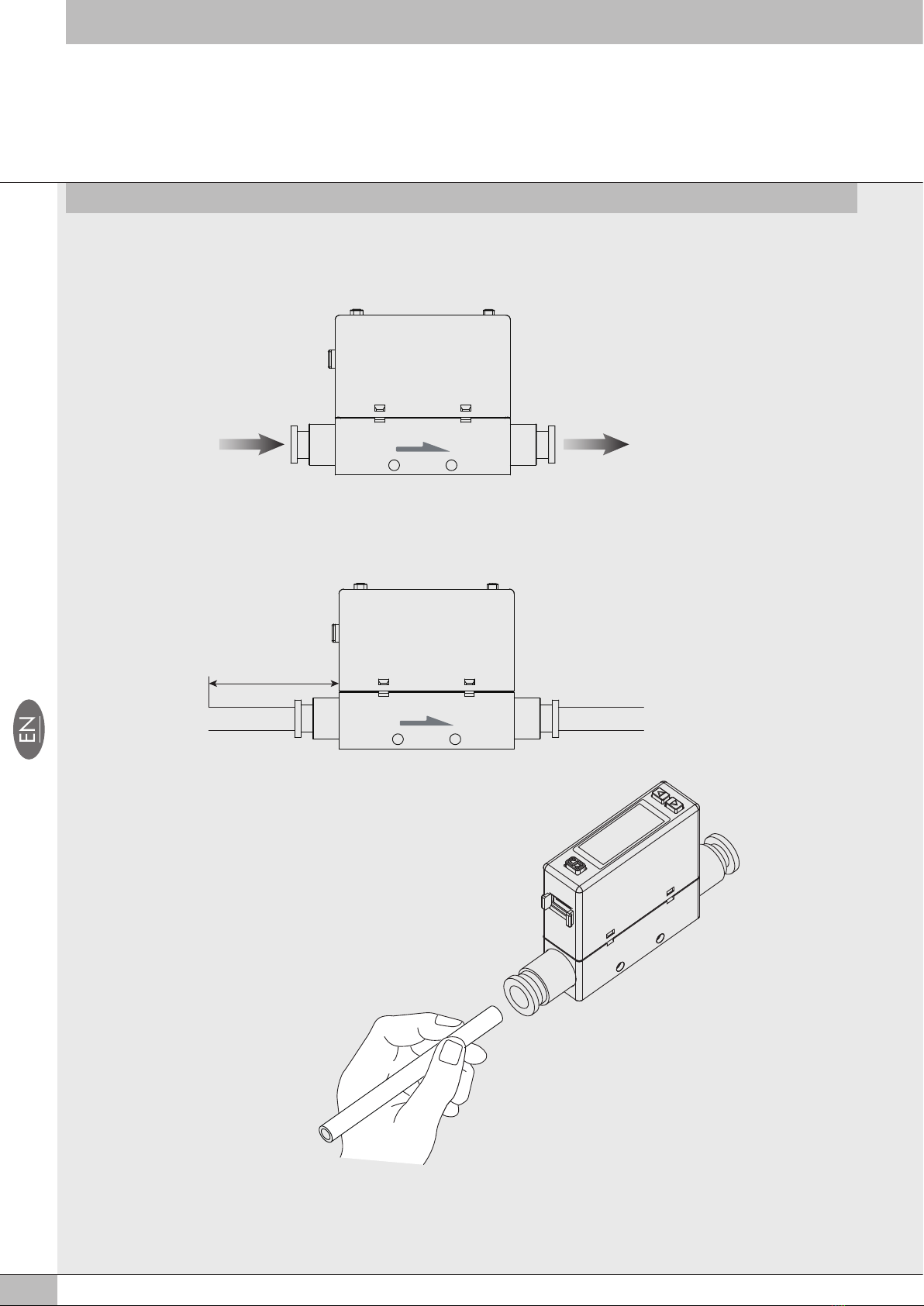
1.1 Piping
Install the pipe by following the arrow indication that shows the air flow
direction on the product.
Blow the air to flush out the foreign matters,
dust and etc. before installing the pipe.
Uncleaned air may cause malfunction or
damage to the product.
Piping for the One-Touch Fitting, insert the
tube firmly into the fitting and make sure it
cannot be pulled out.
Also using the proper tube cutter is
recommended to ensure square
edge tube.
Flow direction
Use straight piping 8cm or longer to connect the Piping Port (Inlet side).
If straight piping is not installed, the accuracy may vary by ± 2% F.S..
※Straight Piping: The pipe is without bending and the cross sectional areas of the
pipe keeps the same.
Piping Port
(Inlet side)
straight piping 8cm
or longer
Piping Port
(Outlet side)
9
@2019 KITA Sensor Tech. Co., LTD. URL hiip://www.kita.com.tw
-6-
KFP01 Series Instruction Manual
Installation
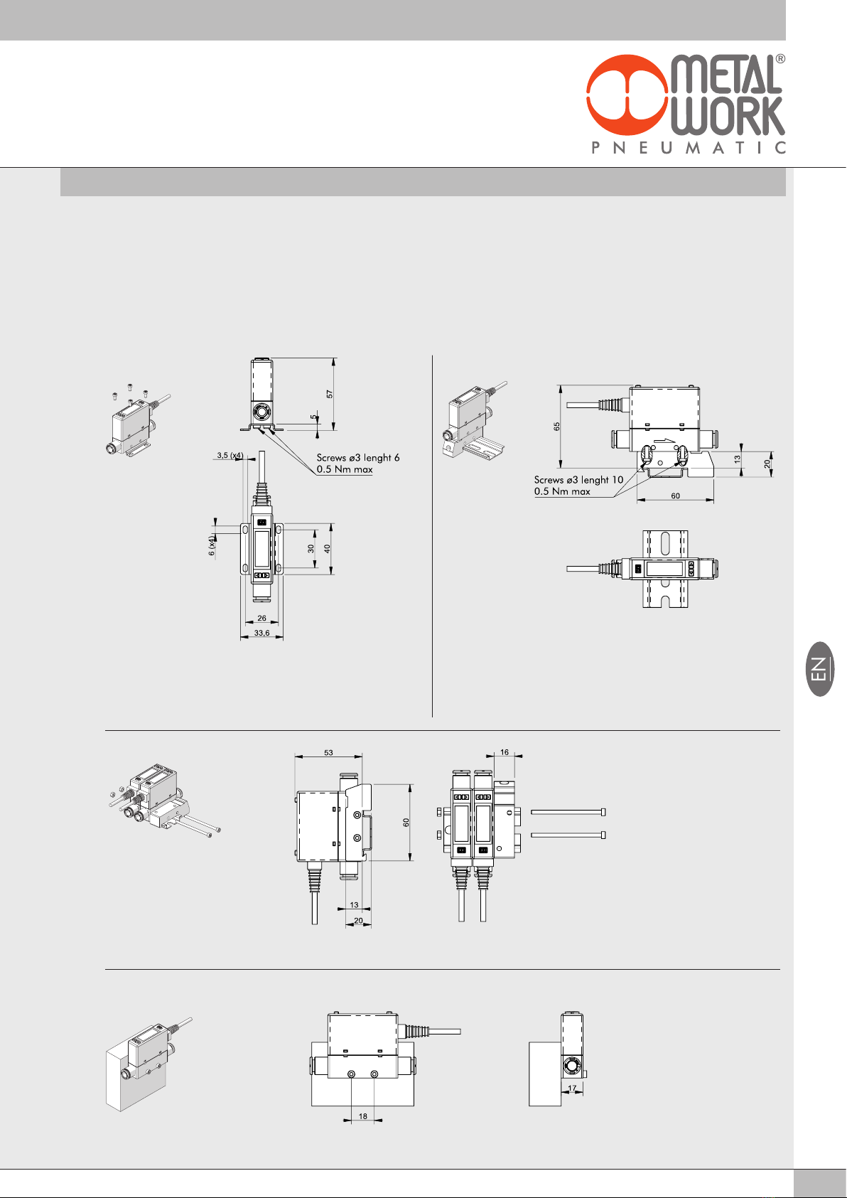
Mounting
screw
Mounting screw Mounting screw
P Type
Size : 3.0
Length : 6mm
※The tightening torque for bracket mounting screws
should be under 0.5 ± 0.1 N.m.
1.2 Mounting Bracket / Optional Parts
The LCD display may be difficult to see at certain angles.
The sensor can be installed horizontally or vertically, but the flow rates
may change because of the installation way of the product or piping.
The tightening torque for screws should be under 0.5 ±0.1 N.m.
1.Horizontal mounting
(by Through-Hole)
2.Bracket mounting
AB
D
C
Fixing with bracket code 90009A001 using the included Ø3
self-tapping screws and M3 screws Single fixing on DIN bar with code bracket 90009A002 using the
included Ø3 self-tapping screws
Multiple fixing on DIN bar with code bracket 90009A002 using the lateral holes Ø3.4 with M3 screws and nuts
Side fixing using M3 screws, minimum length 23 mm

10
@2019 KITA Sensor Tech. Co., LTD. URL hiip://www.kita.com.tw
-8-
Installation Instructions
KFP01 Series Instruction Manual
●PNP Output / Analog Voltage Output / External Input
●PNP Output / Analog Current Output / External Input
1
2
3
4
5
6
Brown (Power supply +)
Brown (Power supply +)
Blue (Power supply –)
Blue (Power supply –)
Black (Output 1)
White (Output 2)
Black (Output 1)
White (Output 2)
Yellow (External input)
Yellow
(External input)
Orange
(Analog output)
Orange
(Analog output)
1
2
3
4
5
6
1kΩ
1.3 Wiring Diagrams
1.3.
1PNP Output, Analog Output and External Input
Brown
Orange
Yellow
Black
White
Blue
Pin No. Line color Content
1 Brown Power supply (DC 12 to 24V DC)
4 Black Output 1 (Max. load current:125mA)
5 White Output 2 (Max. load current:125mA)
3 Yellow External input
2 Orange Analog voltage output:1 -5V
Analog current output:4 -20mA
6 Blue 0V (GND)
1
2
3
4
5
6
Main CircuitMain Circuit
Load
Load
Load
Load
Load

11
2.1 Names and Functions of Individual Parts
Setting Button
Use for selection each mode
and set value confirmation.
▼Button
▲Button
Use for mode selection,
ON/OFF switching and
set value adjustment.
Use for mode selection,
ON/OFF switching and
set value adjustment.
Lead Wire
Connector
Piping Port (Inlet side)
Output 1 Indicator
3 Color LCD Display Flow Symbol
Flow Display
Button
Button
Analog Signal Indicator
Output 2 Indicator
Output 1 Indicator
Output 2 Indicator
Analog Signal Indicator
Pressure Symbol
Pressure Display
Setting Button
Pressure Unit
Display Section
Flow Unit
Display Section
Piping Port (Outlet side)
LCD Display
Through-Hole
Use to mount the product
on a plate directly.
Body
Connector
Ag OUT1OUT2 Ag OUT1OUT2
kgf/cm2bar psi kPa Pulse ft3/min mL3/min
2. HOW TO USE

12
2.2 Function Instruction
●Function Setting Mode
●Measurement Mode
Item Explanation
[F-01]
[F-02]
[F-03]
[F-04]
[F-05]
[F-06]
[F-08]
[F-09]
[F-10]
[F-91]
[F-92]
[F-94]
[F-95]
[F-99]
[oUt1 ] OUT 1 setting
[oUt2 ] OUT 2 setting
[CLor ] LCD Display color selection
[rESP] Response time selection
[UPdA ]
Display refresh time selection
[Unit ] Unit selection
[rEFE] Flow reference standard
selection
[ AnG ] Analog output selection
[EEPr] Accumulated value hold
selection
[ diS ] Flow sensor display mode
selection
[ ECo ]
Power-Save mode selection
[ inP ] External input selection
[FinE ] Fine adjustment Setting
[FoUt ] Forced output function
[rESt ] Reset to the default setting
Select Output 1 corresponding to flow sensor or
pressure sensor. Set the flow rate or pressure
value to switch ON/OFF.
Select Output 2 corresponding to flow sensor or
pressure sensor. Set the flow rate or pressure
value to switch ON/OFF.
Select back light color and display mode.
Select the response time for analog output.
Pressure sensor: 2.5ms ~ 1500ms.
Flow sensor: 50ms ~ 1500ms.
Display refresh cycle can be set in 200ms, 500ms
or 1000ms.
Select the UNIT of pressure / flow sensor.
Select the flow value is shown under standard (ANR)
or normal condition (NOR).
Select the analog corresponding to pressure or flow
sensor.
To save the last accumulated flow value every 2 or
5 minutes.
Select to display Instantaneous Flow or Accumulated
Flow Mode.
Select if turn on power-save mode to reduce power
consumption
Select for Accumulated flow rate zero clear,
Auto-Shift or Auto-Shift zero.
The displayed value can be adjusted slightly.
To turn the analog ON/OFF forcibly.
Return to the factory default setting.
[F-07]
Function
Code
Item Explanation
Pressure display
Flow display
Accumulated flow rate display
Pressure zero setting
Instantaneous Flow rate zero setting
Accumulated flow rate zero clear
Peak value display
Bottom value display
Key lock/unlock mode
Display pressure value.
Display instantaneous flow rate.
Display accumulated flow rate.
The displayed pressure value can be adjusted to "0".
The displayed instantaneous flow rate value can be adjusted to "0".
The accumulated flow rate can be set to "0".
The maximum pressure or instantaneous flow can be detected when
the power is supplied for a period.
The minimum pressure or instantaneous flow can be detected when
the power is supplied for a period.
To prevent errors occurring due to unintentional changes of the set values.

13
@2019 KITA Sensor Tech. Co., LTD. URL hiip://www.kita.com.tw
-12-
KFP01 Series Instruction Manual
How to Use
At Measurement Mode, press button for more than 3 sec. to display
[F-01]. Press or button to select other setting functions.
Press for 3 sec. at Function Setting Mode to return to Measurement
Mode.
2.3 Operation Instructions
Function Selection Mode
Ag
kPa L /min
Ag
kPa L /min
Ag
kPa L /min
Measurement Mode
Function Selection Mode
Press button for
more than 3 sec.
Enter in each function setting
Ag
kPa L /min
Press button

14
@2019 KITA Sensor Tech. Co., LTD. URL hiip://www.kita.com.tw
-13-
KFP01 Series Instruction Manual
How to Use
2.3.1 [F-01] OUT1 Setting Selection
Setting corresponding sensor and operating mode of OUT1.
●1. Flow sensor setting
Press or button at Function Setting Mode to display
[F-01] [oUt1].
Ag
kPa L /min
Sensor Selection
Press or button to select
flow sensor of OUT1.
Flow sensor
Ag
kPa L /min
Selected
Output
Sensor
Pressure sensor
Press button
(to be continued)
Ag
kPa L /min
Output Mode Setting
Select output mode:
Press or button to select output
mode of OUT1.
4 output modes included.
Hysteresis Mode
※NOTE:The Accumulated Pulse Output Mode can only be set in OUT1, and OUT2 does not have this setting.
Ag
kPa L /min
Selected
Mode
Selected
Sensor
Window Comparator Mode Accumulated Output Mode
Ag
kPa L /min
Ag
kPa L /min
Ag
kPa L /min
Accumulated Pulse
Output Mode
Ag
kPa Pulse L /min
Press button
Press button
15
@2019 KITA Sensor Tech. Co., LTD. URL hiip://www.kita.com.tw
-14-
KFP01 Series Instruction Manual
How to Use
Fixed Hysteresis
Mode
NO mode NC mode
Ag
kPa L /min
Selected
Output
Selected
Mode
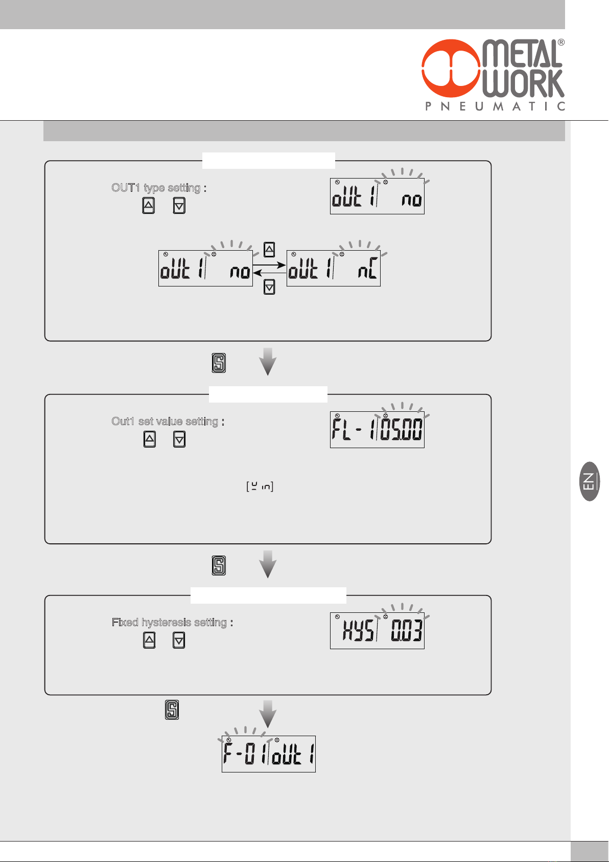
Output Type Setting
OUT1 type setting :
Press or button to select OUT1
type.
Ag
kPa L /min
Ag
kPa L /min
※NOTE:Type setting will not display when Accumulated Pulse Output Mode is set.
Ag
kPa L /min
Set ValueSelected
Mode
Set Value Setting
Out1 set value setting :
Press or button to adjust the set
value.
Hysteresis Mode [HYS]:[FL-1],[FH-1]
Window Comparator Mode :[FL-1],[FH-1]
Accumlated Output Mode [ADD]:[AddL],[AddH]
※NOTE:Set value setting will not display when Accumulated Pulse Output is set.
Ag
kPa L /min
Set Value
Fixed Hysteresis Setting
Fixed hysteresis setting :
Press or button to adjust fixed
hysteresis value.
※NOTE:Fixed hysteresis setting will not display when Hysteresis Mode, Accumulated Output Mode and
Accumulated Pulse Output Mode is set.
Ag
kPa L /min
Press button
Press button
Press button to return to
Function Selection Mode

16
@2019 KITA Sensor Tech. Co., LTD. URL hiip://www.kita.com.tw
-15-
KFP01 Series Instruction Manual
How to Use
●2. Pressure sensor setting
Press or button at Function Selection Mode to display
[F-01] [oUt1].
Output Mode Setting
Select output mode:
Press or button to select output
mode of OUT1.
Hysteresis Mode
Ag
kPa L /min
Window Comparator Mode
One Point Set Mode
Ag
kPa L /min
Ag
kPa L /min
Ag
kPa L /min
Press button
Ag
kPa L /min
Sensor Selection
Press or button to select
pressure sensor of OUT1.
Flow sensor
Ag
kPa L /min
Pressure sensor
Ag
kPa L /min
Press button
(to be continued)
Press button
Selected
Output
Sensor
Selected
Mode
Sensor
17
@2019 KITA Sensor Tech. Co., LTD. URL hiip://www.kita.com.tw
-16-
KFP01 Series Instruction Manual
How to Use
NO Mode NC Mode
Ag
kPa L /min
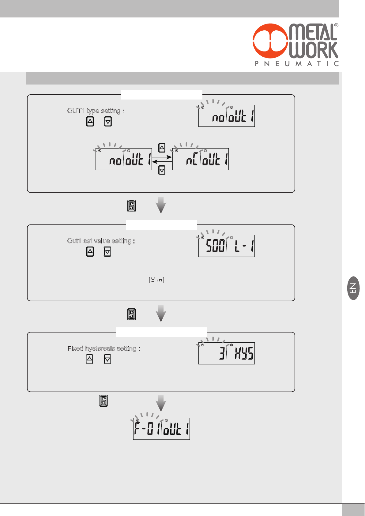
Output Type Setting
OUT1 type setting :
Press or button to select OUT1
type.
Ag
kPa L /min
Set Value Setting
Out1 set value setting :
Press or button to adjust the set
value.
Hysteresis Mode [HYS]:[L-1],[H-1]
Window Comparator Mode :[L-1],[H-1]
One Point Set Mode [oPS]:[P-1]
Ag
kPa L /min
Fixed Hysteresis Setting
Fixed hysteresis setting :
Press or button to adjust fixed
hysteresis value.
NOTE:Fixed hysteresis setting will not display when Hysteresis Mode is set.
Ag
kPa L /min
Ag
kPa L /min
Ag
kPa L /min
Press button
Press button
Fixed Hysteresis
Mode
Set Value
Selected
Mode
Output
Selected
Set Value
Mode
Press button to return to
Function Selection Mode

18
OFF
ON
OFF
ON
Flow / Pressure
Hysteresis Mode
Hysteresis Mode
FL-1(FL-2)
L-1(L-2)
FH-1(FH-2)
H-1(H-2)
OFF
ON
OFF
ON
FL-1(FL-2)
L-1(L-2)
FH-1(FH-2)
H-1(H-2)
OFF
ON
0 L
OFF
ON
0 L
Time
AdH1 AdL1
AdH2 AdL2
OFF
ON
Time
50ms
Flow Range 500mL
5mL
1000mL 5L 10L 50L 100L 200L
10mL 0.05L 0.1L 1L 2L0.5L
Pulse Output Rate
Normal Open Mode
Normal Close Mode
FL-1(FL-2)
L-1(L-2)
FH-1(FH-2)
H-1(H-2)
OFF
ON
OFF
ON
P-1(P-2)
FL-1(FL-2)
L-1(L-2)
FH-1(FH-2)
H-1(H-2)
P-1(P-2)
Time
AdH1 AdL1
AdH2 AdL2
Pressure
Flow
【NOTE:】
*1. In case hysteresis is set at less than or equal to 2 digits, switch output may chatter if input pressure fluctuates near the set point.
*2. When using window comparator mode, the difference between two set points must be greater than the fixed hysteresis, otherwise
will cause the switch output to malfunction.
Window Comparator Mode
One Point Set Mode
Accumulated Output Mode
Accumulated Pulse Output Mode
Flow / Pressure
Accumulated Output Mode
Flow
One Point Set Mode
Pressure
Window Comparator Mode
Flow / Pressure
Flow / Pressure

19
@2019 KITA Sensor Tech. Co., LTD. URL hiip://www.kita.com.tw
-18-
KFP01 Series Instruction Manual
How to Use
2.3.2 [F-02] OUT2 Setting Selection
Setting corresponding sensor and operating mode of OUT2.
1. Press or button at function setting mode to start "OUT 2
Setting" [F-02] [oUt2].
2. Check the [F-01]for the same follow setting.
NOTE:The OUT2 Setting dose not have Accumulated Pulse Output Mode.

20
@2019 KITA Sensor Tech. Co., LTD. URL hiip://www.kita.com.tw
-19-
KFP01 Series Instruction Manual
How to Use
2.3.3 [
F-03
] LCD Display Color Selection
4 LCD Display Color Modes of output value selection.
< Operation >
Press or button at Function Selection Mode to display
[F-03] [CLor].
Output Selection
Press the or button to select color
display for OUT1 or OUT2.
Display color of OUT1
Ag
kPa L /min
Display color of OUT2
Display Color Mode Selection
Press the or button to select
Display Color Mode.
ON : Green
OFF : Red
ON : Red
OFF : Green
ON : Green
OFF : Green
ON : Red
OFF : Red
Ag
kPa L /min
Display Color
Mode
Selected
Mode
Ag
kPa L /min
Ag
kPa L /min
Ag
kPa L /min
Ag
kPa L /min
Ag
kPa L /min
Ag
kPa L /min
Ag
kPa L /min
Press button
Press button
Selected
Output
Color
Display
Press button to return to
Function Selection Mode
Table of contents
Other Metal Work Measuring Instrument manuals

Popular Measuring Instrument manuals by other brands


Seetru
Seetru G23 Installation, operating, & maintenance instructions

Bedfont
Bedfont G210 operating manual

Precaster
Precaster TIO30 Operation manuals

SIGLENT
SIGLENT SHA800A quick guide

Alcohol Monitoring Systems
Alcohol Monitoring Systems SCRAM Agent reference guide

Ryobi
Ryobi Phone Works ES3001 Important safety instructions


