Metallkraft PRM 30 F User manual

PRM 30 F
Operating Instructions
PRM 30 F
PRM F
Ring Bending Machine
PRM 31 F
PRM 35 F

2 PRM F | Version 1.07 | EN
Imprint
Product identification Ring Bending Machine
PRM 30 F Item n mber: 381 2030
PRM 31 F Item n mber: 381 2031
PRM 35 F Item n mber: 381 2035
Manufacturer Stürmer Maschinen GmbH
Dr.-Robert-Pfleger-Str. 26
D-96103 Hallstadt
Fax: 0049 (0) 951 96555 - 55
Email: [email protected]
Internet: www.metallkraft.de
Indications regarding the operating
instructions
Original Instr ctions
Edition: 29.09.2020
Version: 1.07
Lang age: english
A thor: RL
Indications regarding the copyright Copyright © 2020 Stürmer Maschinen GmbH, Hallstadt, Germany.
The contents of these operating instr ctions are the sole property of the com-
pany Stürmer Maschinen GmbH.
Passing on as well as copying of this doc ment, the se and distrib tion of its
content are prohibited if not explicitly permitted. Contraventions are liable to
compensation.
S bject to technical modifications and error.

PRM F | Version 1.07 | EN 3
Content
1 Introduction .........................................................................4
1.1 Copyright............................................................................................... 4
1.2 Cost mer Service ................................................................................. 4
1.3 Limitation of liability............................................................................... 5
2 Safety....................................................................................5
2.1 Symbol explanation............................................................................... 5
2.2 Responsibility of the operator ............................................................... 6
2.3 Personnel req irements........................................................................ 7
2.3.1 Q alifications.................................................................................. 7
2.4 Personal protective eq ipment ............................................................. 8
2.5 Safety markings on the ring bending machine...................................... 8
2.6 Safety eq ipment.................................................................................. 9
2.6.1 Installed safety devices .................................................................. 9
3 Intended use ......................................................................10
4 Technical ata ...................................................................10
4.1 Type plate ........................................................................................... 11
5 Transport, Packaging, Storage ........................................11
5.1 Delivery and Transport........................................................................ 11
5.2 Packaging ........................................................................................... 13
5.3 Storage ............................................................................................... 13
6 escription of device ........................................................14
6.1 Scope of delivery ................................................................................ 14
7 Assembly ...........................................................................15
7.1 Set p.................................................................................................. 15
8 Commissioning .................................................................19
8.1 Connect the ring bending machine to the mains................................. 21
9 Operation ...........................................................................21
9.1 Controls............................................................................................... 22
9.2 Mo nt standard bending rollers .......................................................... 23
9.3 Adj st side g ide rollers...................................................................... 24
9.4 Bending profiles .................................................................................. 24
9.5 Bending rolls ....................................................................................... 27
9.6 Application examples for bending rolls ............................................... 29
9.7 Bending tolerances of different profiles............................................... 30
10 Cleaning and maintenance .............................................31
10.1 Cleaning............................................................................................ 32
10.2 L brication ........................................................................................ 33
10.3 Cleaning the electrical box................................................................ 33
10.4 Disr ptions, Possible ca ses and meas res .................................... 33
11 isposal, Recycling of old equipment...........................34
11.1 Decommission .................................................................................. 34
11.2 Disposal of electrical eq ipment ....................................................... 34
11.3 Disposal of l bricants........................................................................ 34
12 Spare parts.......................................................................34
12.1 Spare parts order.............................................................................. 35
12.2 Spare parts dawings PRM 30 F........................................................ 36
12.3 Spare parts drawing PRM 31 F ........................................................ 38
12.4 Spare parts drawing PRM 35 F ........................................................ 39
13 Electrical wiring diagrams ..............................................40
13.1 Electrical wiring diagram PRM 30 F ............................................... 40
13.2 Electrical wiring diagrams PRM 31 F............................................... 42
13.3 Electrical wiring diagrams PRM 35 F .............................................. 45
14 EC eclaration of Conformity ........................................47

4 PRM F | Version 1.07 | EN
Introduction
1 Introduction
Yo have made a good choice in p rchasing a METALLKRAFT Ring Bending
Machine.
Thoroughly read the operating instructions before commissioning the
machine.
This informs abo t the proper commissioning, the intended se as well as the
safe and efficient operation and maintenance of the machine.
The operating instr ctions are part of the machine. It m st always be stored at
the place of se of the ring bending machine. In addition, the local accident
prevention reg lations and general safety reg lations apply for the area of ap-
plication of the ring bending machine.
Ill strations in this operating man al serve the general nderstanding and may
deviate from the act al design.
1.1 Copyright
The contents of this man al are protected by copyright. Their se is permitted
when sing the machine. Any f rther se is not permitted witho t the written
permission of the man fact rer.
We hereby apply for trademark, patent and design rights to protect o r pro-
d cts, if this is possible in individ al cases. We vigoro sly oppose any infringe-
ment of o r intellect al property.
1.2 Costumer Service
Please contact yo r dealer if yo have any q estions abo t yo r machine or
technical information. There yo will be happy to help with expert advice and
information.
Germany:
Stürmer Maschinen GmbH
Dr.-Robert-Pfleger-Str. 26
D-96103 Hallstadt
Repair-Service:
Fax: 0049 (0) 951 96555-111
Email: service@st ermer-maschinen.de
Spare parts orders:
Fax: 0049 (0) 951 96555-119
Email: ersatzteile@st ermer-maschinen.de
We are always interested in information and experiences that arise from the
application an can be val able for the improvement of o r prod cts.

Safety
PRM F | Version 1.07 | EN 5
1.3 Limitation of liability
All Information and notes in these operating instr ctions were s mmarised ta-
king the applicable standards and r les, the state-of-the-art and o r long-term
knowledge and experiences into consideration.
In the following cases, the man fact rer ass mes no liability for damages:
- Fail re to observe the operating instr ctions,
- Improper se,
- Use of ntrained personnel,
- Una thorized conversions,
- Technical changes,
- Use of na thorized spare parts.
The act al scope of delivery may differ from the explanations and ill strations
described here for special versions, when sing additional order options or
d e to the latest technical changes.
The obligations agreed in the delivery contract, the general terms and conditi-
ons as well as the delivery conditions of the man fact rer and the legal reg la-
tions valid at the time of the concl sion of the contract apply.
2 Safety
This section provides an overview of all major safety packages for personal
protection and safe and tro ble-free operation. F rther task-related safety in-
str ctions are contained in the individ al chapters.
2.1 Symbol explanation
Safety instructions Safety instr ctions are indicated by symbols in these operating instr ctions.
The safety instr ctions are initiated by signal words that express the extent of
the hazard.
ANGER!
This combination of symbol and signal word indicates an
immediately dangero s sit ation. It leads to death or serio s
inj ry if it is not avoided.
WARNING!
This combination of symbol and signal word indicates a
potentially dangero s sit ation. It leads to death or serio s
inj ry if it is not avoided.
CAUTION!
This combination of symbol and signal word indicates a
potentially dangero s sit ation. It can ca se minor or minor
inj ries if not avoided.

6 PRM F | Version 1.07 | EN
Safety
Tips and recommendations
To red ce the risk of personal inj ry and property damage and to avoid dange-
ro s sit ations, the safety instr ctions in this man al m st be observed.
2.2 Responsibility of the operator
Operator The operator is the person who operates the machine for commercial or eco-
nomic p rposes himself or leaves it to a third party for se or application and
bears the legal prod ct responsibility for the protection of the ser, personnel
or third parties d ring operation.
Operator obligations The operator is the person who operates the machine for commercial or eco-
nomic p rposes himself or leaves it to a third party for se or application and
bears the legal prod ct responsibility for the protection of the ser, personnel
or third parties d ring operation.
- The operator m st obtain information abo t the applicable occ pational
safety reg lations and, in a risk assessment, m st also determine addi-
tional hazards res lting from the special working conditions at the place
of se of the machine. He m st implement these in the form of operating
instr ctions for the operation of the machine.
- The operator m st check d ring the entire period of se of the machine
whether the operating instr ctions he has prepared comply with the c r-
rent state of the reg lations and adj st them if necessary.
- The operator m st clearly reg late and determine the responsibilities for
installation, operation, tro bleshooting, maintenance and cleaning.
- The operator m st ens re that all persons handling the machine have
read and nderstood this man al. In addition, he m st train the staff at
reg lar intervals and inform them abo t the dangers.
- The operator m st provide the personnel with the necessary protective
eq ipment and bind the wearing of the req ired protective eq ipment.
F rthermore, the operator is responsible for ens ring that the machine is al-
ways in perfect technical condition. Therefore, the following applies:
- The operator m st ens re that the maintenance intervals described in
this man al are observed.
- The operator m st have all safety eq ipment reg larly checked for f nc-
tionality and completeness.
ATTENTION!
This combination of symbol and signal word indicates a
potentially hazardo s sit ation which, if not avoided, co ld
res lt in property damage and environmental damage.
NOTE!
This combination of symbol and signal word indicates a po-
tentially dangero s sit ation. It can lead to material and env-
ironmental damage if it is not avoided.
Tips and recommendations
This symbol indicates sef l tips and recommendations as
well as information for efficient and tro ble-free operation.

Safety
PRM F | Version 1.07 | EN 7
2.3 ersonnel requirements
2.3.1 Qualifications
The vario s tasks described in this man al place different demands on the
q alifications of the people entr sted with these tasks.
Only persons who are expected to carry o t this work reliably are permitted for
all work. Persons whose reactivity z. As infl enced by dr gs, alcohol or dr gs
are not allowed.
This man al identifies the q alifications of the persons listed below for the dif-
ferent tasks:
Operator The operator has been instr cted in a briefing by the operator abo t the tasks
assigned to him and possible dangers of improper behavior. The operator may
only carry o t tasks that go beyond normal operation if this is specified in this
operating man al and the operator has expressly entr sted this to him.
Electrician D e to their professional training, knowledge and experience as well as
knowledge of the relevant standards and reg lations, the electrician is in a po-
sition to carry o t work on electrical installations and to recognize and avoid
possible dangers independently.
The electrician is specially trained for the work environment in which he works
and knows the relevant standards and reg lations.
Specialist staff D e to their technical training, knowledge and experience as well as
knowledge of the relevant standards and reg lations, q alified personnel are
in a position to carry o t the work assigned to them and to recognize potential
dangers independently and to avoid hazards.
Manufacturer Certain work may only be carried o t by specialist personnel of the man fact -
rer. Other personnel are not a thorized to carry o t this work. To carry o t the
work, contact o r c stomer service.
WARNING!
anger due to insufficient qualification of per-
sons!
Ins fficiently q alified persons can not assess the risks
involved in handling the machine and expose themselves
and others to the risk of serio s or fatal inj ries.
- All work sho ld only be carried o t by q alified persons.
- Keep inadeq ately q alified persons o t of the work area.
8 PRM F | Version 1.07 | EN
Safety
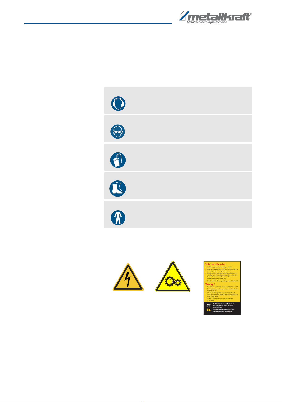
2.4 ersonal protective equipment
Personal Protective Eq ipment is intended to protect people from compromi-
sing safety and health at work. Personnel m st wear personal protective
eq ipment d ring the vario s operations on and with the machine, which are
specifically indicated in the separate sections of this man al.
The following section explains personal protective eq ipment::
2.5 Safety markings on the ring bending machine
Vario s safety markings are attached to the ring bending machine (Fig. 1),
which m st be observed and followed.
Fig. 1: Safety markings - 1 Warning of dangero s electrical voltage - 2 Warning abo t rotating ma-
chine parts, danger of cr shing d ring bending - 3 safety instr ctions
The safety markings attached to the ring bending machine m st not be remo-
ved. Damaged or missing safety markings can lead to malf nctions, personal
inj ry and property damage. They are to be replaced immediately.
If the safety markings are not immediately recognizable and comprehensible,
the ring bending machine m st be taken o t of service ntil new safety mar-
kings have been made.
Ear protection
The goggles protect the eyes from flying parts and liq id
splashes.
Eye protection
The goggles protect the eyes from flying parts and liq id
splashes.
Protective gloves
The protective gloves protect the hands from sharp-edged
components as well as from friction, abrasions or deeper
inj ries.
Safety shoes
The safety shoes protect the feet against br ising, falling
parts and slipping on slippery s rfaces.
Protective clothing
The protective clothing is tight-fitting clothing with low tear
resistance.
1 2 3
Safety
PRM F | Version 1.07 | EN 9
2.6 Safety equipment
2.6.1 Installed safety devices
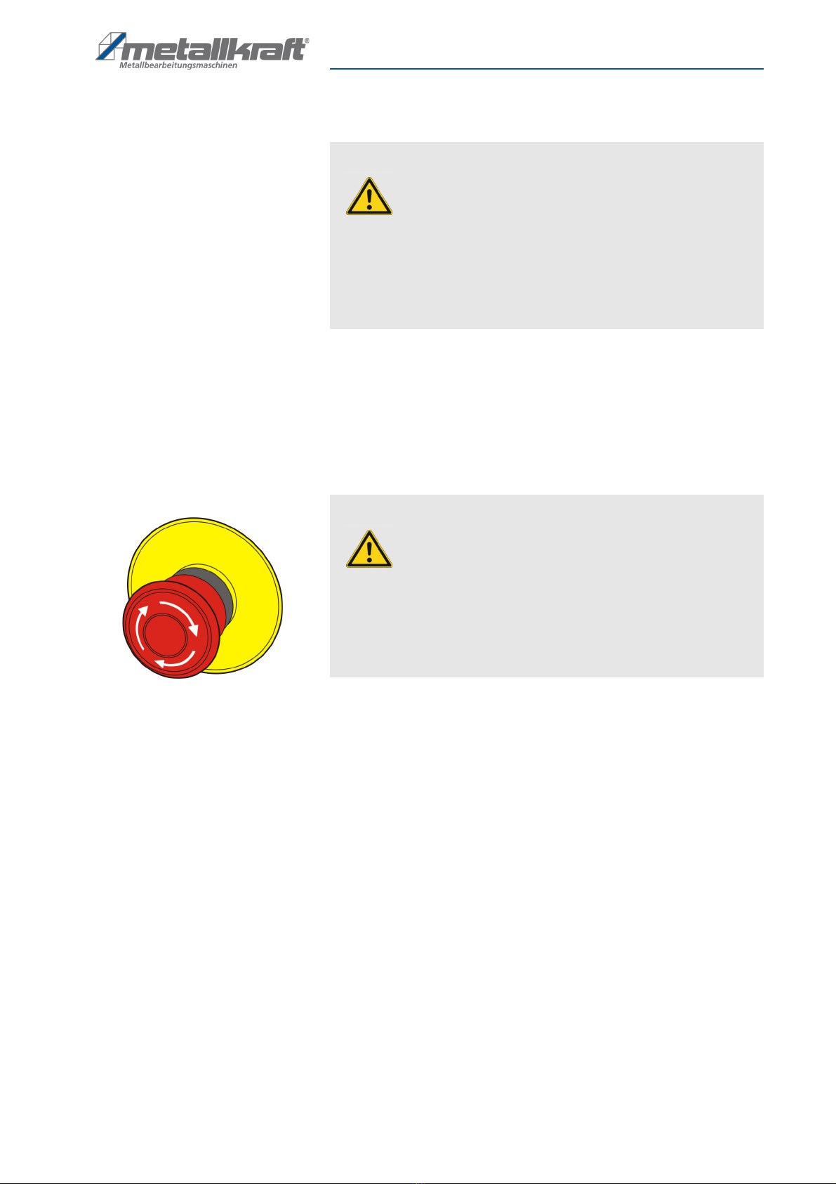
Emergency stop button Press the emergency stop b tton (Fig. 2) located on the control panel control
panel and the machine will stop immediately. The power s pply is switched off
or the drives are mechanically disconnected. After the emergency stop b tton
has been pressed, it m st be nlocked by t rning so that it can be switched on
again.
Fig. 2: Emergency stop b tton
WARNING!
anger to life due to non-functioning safety
devices!
Fail re to operate or disable the safety eq ipment can res lt
in serio s inj ry or even death.
- Before starting work, check that all safety eq ipment is in
place and correctly installed.
- Never override or bypass safety devices.
- Ens re that all safety devices are always accessible.
WARNING!
anger to life due to uncontrolled restarting!
Uncontrolled restarting of the machine can lead to serio s
inj ries or even death.
- Before switching on again, make s re that the ca se of the
emergency stop has been eliminated and all safety devices
are installed and f nctional.
- Only nlock the emergency stop b tton if there is no longer
any danger.

10 PRM F | Version 1.07 | EN
Intended use
3 Intended use
The machine is sed excl sively for bending radii on profiles, pipes and solid
materials. It sho ld be noted that certain profiles or materials may req ire spe-
cial wheels that are not incl ded. Only profiles and materials may be proces-
sed with the rollers provided. Proper se also incl des compliance with all in-
formation in this man al. Any se beyond the intended se or otherwise is
considered mis se.
Una thorized modifications or changes to the ring bending machine can invali-
date the CE conformity of the ring bending machine and are prohibited. The
company Stürmer Maschinen GmbH ass mes no liability for design and tech-
nical changes to the ring bending machine.
The improper se of the ring bending machine as well as the disregard of the
safety reg lations or the operating instr ctions excl de a liability of the man -
fact rer for res lting damage to persons or objects and ca se the warranty to
lapse!
4 Technical Data
WARNING!
anger in case of misuse!
Mis se of the machine can lead to dangero s sit ations.
- Only operate the machine in the power range specified in
the technical data.
- Never bypass or override the safety devices.
- Only operate the machine in a technically perfect condition.
General data PRM 30 F PRM 31 F PRM 35 F
Shaft Diameter 30 mm 30 mm 50 mm
Roll diameter above 148 mm 148 mm 155 mm
Roll diameter below 118 mm 118 mm 155 mm
Speed max. 12 U/min 12 U/min 9 U/min
Dimensions [mm] 650 x 500 x 1400 600 x 800 x 1450 1000 x 750 x 1400
Weight 220 kg 220 kg 400 kg
Engine power 0,8 kW 0,85 kW 1,5 kW
Operating voltage 400 V 400 V 400 V
Freq ency 50 Hz 50 Hz 50 Hz
Phases 3 3 3

Transport, Packaging, Storage
PRM F | Version 1.07 | EN 11
4.1 Type plate
The nameplate with the following data for identification as well as the CE mar-
king are attached to the ring bending machine (Fig. 3).
Fig. 3: Type plate and CE marking of the ring bending machine PRM 30 F
5 Transport, ackaging, Storage
5.1 Delivery and Transport
elivery Check the machine for visible transport damage after delivery. If the machine
is damaged, it m st be reported immediately to the transport company or the
dealer.
Transport Improper transport is accident-prone and can ca se damage or malf nctions
for which we do not grant any liability or g arantee.
Transport the scope of delivery sec red against shifting or tilting with a s ffi-
ciently dimensioned ind strial tr ck to the installation site.
WARNING!
Severe or fatal inj ries may occ r if parts of the machine t mble or
fall down from the
forklift tr ck, pallet tr ck or from the transport vehicle.
Follow the instr ctions and information on the transport box.
Note the total weight of the machine. The weight of the machine is indica-
ted in the "Technical data" of the machine. When the machine is npac-
ked, the weight of the machine can also be read on the rating plate.
Only se transport devices and load s spension gear that can hold the
total weight of the machine.
WARNING!
The se of nstable lifting and load s spension eq ipment that might
break nder load can ca se severe inj ries or even death. Check that the
lifting and load s spension gear has s fficient load-bearing capacity and
that it is in perfect condition.
Observe the accident prevention reg lations iss ed by yo r Employers
Liability Ins rance Association or other competent s pervisory a thority,
responsible for yo r company.
Fasten the loads properly.
12 PRM F | Version 1.07 | EN
Transport, Packaging, Storage
General risks during internal transport
Devices may only be transported by a thorized and q alified persons. Act re-
sponsibly d ring transport and always consider the conseq ences. Refrain
from daring and risky actions.
Gradients and descents (e.g. driveways, ramps and the like) are partic larly
dangero s. If s ch passages are navoidable, special ca tion is req ired.
Before starting the transport check the transport ro te for possible danger
points, nevenness and dist rban-ces as well as for s fficient strength and
load capacity.
Danger points, nevenness and dist rbance points m st be inspected before
transport. The removal of danger spots, dist rbances and nevenness at the
time of transport by other employees leads to considerable dangers.
Caref l planning of internal transport is therefore essential.
Transport with a forklift / pallet truck:
For shipping, the machine is firmly mo nted on a pallet so that it can be trans-
ported by forklift or pallet tr ck.
Transport by crane:
The machine can be set p with a crane in a s itable location. To do this, the
machine m st be attached to the crane in accordance with the reg lations
(Fig. 4). The attachment points on the machine are to be sed.
Fig. 4: Transport ring bending machine
For transport, all rollers m st be fixed and all covers m st be attached to the
machine frame.
The machine m st not be rocked d ring transport by crane.
WARNING: ANGER OF TIPPING
The device may be lifted nsec red by a maxim m of 2cm.
Employees m st be o tside the danger zone, the reach of loads.
Warn employees and, if necessary, advise employees of the hazard.
ANGER!
anger to life due to falling of the load!
Falling loads can ca se serio s inj ry or even death.
- Never step nder s spended loads.
- Fix loads caref lly.
- When leaving the workplace, lower the load.

Transport, Packaging, Storage
PRM F | Version 1.07 | EN 13
5.2 ackaging
All packaging materials and packaging aids sed in the machine are recycla-
ble and m st always be recycled.
Cardboard packaging components m st be shredded for collection of waste
paper.
The foils are made of polyethylene (PE) and the pholstery parts made of poly-
styrene (PS). These s bstances m st be handed over to a recycling center or
to the responsible disposal company.
5.3 Storage
Store the machine thoro ghly cleaned in a dry, clean, d st- and frost-free env-
ironment. It m st not be placed in a room with strong oxidizing chemicals.
If the machine m st be stored in a damp room, all electrical components m st
be protected by moist re-absorbing agents. Also, all bare metal parts m st be
greased against r sting.
14 PRM F | Version 1.07 | EN
escription of device
6 Description of device
Illustrations in this operating manual serve the general understanding
and may deviate from the actual design.
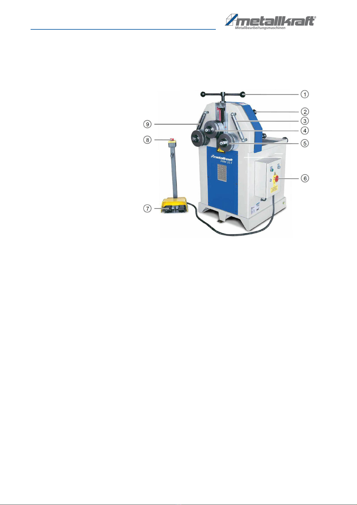
Fig. 5: Operating elements of the ring bending machine PRM 35 F
6.1 Scope of delivery
Standard accessories - included The ring bending machine is delivered with:
- Hardened standard bending rolls
- 2 driven rollers
- mechanically adj stable pper roller
- Shafts made of special steel, hardened and gro nd
- lateral g ide rollers, infinitely adj stable for spiral bending
- the possibility of placing the ring bending machine horizontally and verti-
cally.
- a separate control panel with foot control.
- an operating man al.
Optional accessories - not included Optionally, the following special accessories for the ring bending machine can
be ordered:
- Control panel with digital display
- Special g ide rollers laterally for angle iron
- Bending rolls for steel-iron,
- Plastic benders for al min m,
- Rolls in ntypical sizes (made on req est)
- Bending tool for t rning bars
- Bending tool for spiral bending
1 spindle for height adj stment of
pper roll
2 adj sting screw of the lateral
g ide roller
3 Side g ide roller on the right
4 Upper role
5 Lower roll right
6 main switches
7 control panel with pedals
8 EMERGENCY STOP b tton
9 Lateral g ide roller on the left
Assembly
PRM F | Version 1.07 | EN 15
7 Assembly
7.1 Set up
Requirements for the installation
site
To achieve a good f nctioning of the ring bending machine and a long service
life, the site sho ld meet the following criteria.
- The fo ndation m st be level, firm and vibration-free.
- The fo ndation m st not let any l bricant thro gh.
- The installation or working room m st be dry and well ventilated.
- Do not operate machines that ca se d st and chips near the ring ben-
ding machine.
- There m st be s fficient space for the operating personnel, for material
transport as well as for adj stment and maintenance work.
- The site m st have good lighting.
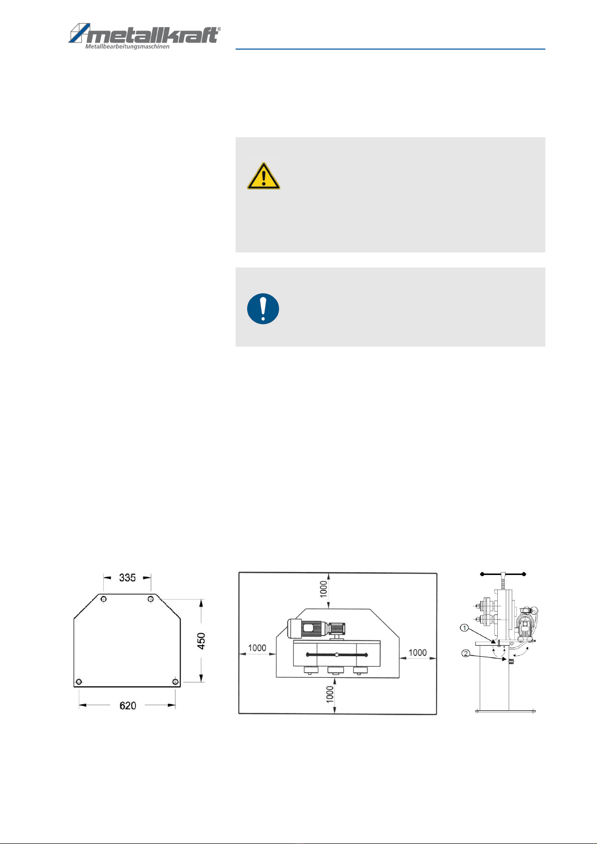
PRM 30 F The PRM 30 F has a swiveling machine head and can th s be sed horizon-
tally and vertically. The following dimensions sho ld be taken into acco nt at
the place of installation or at the workplace (Fig. 6 and 7)
Fig. 6:
Installation dimensions of the ring bending machine PRM 30 F for vertical operation
Fig. 7: Installation dimensions of the ring bending machine PRM 30 F for horizontal operation
WARNING!
anger to life due to undersized buildings!
Overloading of ceiling str ct res leads to serio s property
damage and bodily inj ry p to death!
- If the machine is placed on a self-s pporting b ilding cei-
ling, the dynamic loads d e to the movements m st be ta-
ken into acco nt - the fo ndation m st s pport the ma-
chine.
NOTE!
Property damage due to uneven ground!
An neven s rface ca ses deformation within the machine.
This leads to an inacc rate machining of the workpieces.
- Set p the machine on a flat and level s rface.
16 PRM F | Version 1.07 | EN
Assembly
To tilt the machine head for horizontal operation, proceed as follows:
Step 1: Loosen the screw 1 (Fig. 6, right side).
Step 2: Tilt the machine head 90 °.
Step 3: Screw the screw 1 into the thread 2 (Fig. 6, right side).
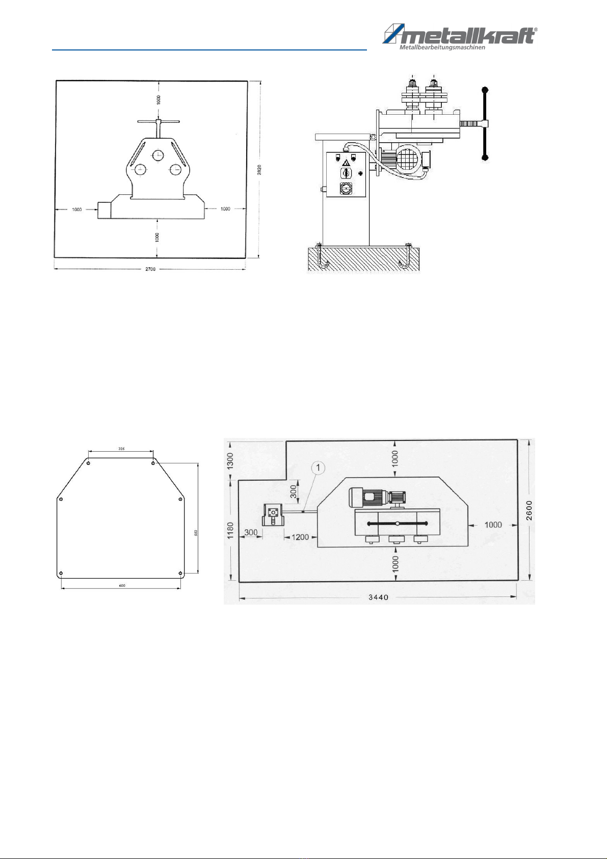
PRM 31 F The PRM 31 F can be sed horizontally and vertically. The following dimensi-
ons sho ld be taken into acco nt at the place of installation or at the workplace
(Fig. 8)
Fig. 8:
Installation dimensions of the ring bending machine PRM 31 for vertical operation

Assembly
PRM F | Version 1.07 | EN 17
PRM 35 F The following dimensions sho ld be taken into acco nt at the place of installa-
tion or at the workplace (Fig. 9)
Fig. 9: Space req irement of the ring bending machine PRM 35 F-left vertical operation, right horizontal operations
- Space in front of and behind the machine: 1000 mm
- Distance from the side of the machine to the wall: at least 1000 mm -
depends on the sizes of the materials to be bent
This area may only be entered by the operator of the machine!
Hazardous areas on the machine
Fig. 10: Hazardo s areas on the ring bending machine
A - Inside the machine, hydra lic system,Power s pply and drive
B - Working area of the machine at the clamping points of the rollers
C - Electric box on the side of the machine, power s pply
WARNING!
Never bring any part of the body close to these danger
zones when the machine is in operation!

18 PRM F | Version 1.07 | EN
Assembly
Setting up the ring bending machine
Step 1: Check the gro nd with a spirit level for horizontal alignment, if neces-
sary, compensate for slight nevenness.
Step 2: Park the ring bending machine on a flat, firm and vibration-free gro nd.
Step 3: Sec re the ring bending machine with gro nd anchors to the gro nd.
Step 4: Connect the transportable controller with the standoff rod to the ma-
chine.
Fig. 11: Anchoring the ring bending machine
WARNING!
Crushing!
The machine may tilt d ring deployment and ca se serio s
inj ry.
- The machine m st be set p by at least 2 people together.
Wear safety gloves!
Wear safety shoes!
Wear protective clothing!
NOTE!
After setting p, remove the protective agent from the rol-
lers, which has been applied in the factory to protect against
r sting.
- Use a cloth and s al solvents (eg benzine).
- No water, no nitrolic solvents or similar se!
NOTE!
The moving parts m st be free of dirt and d st.
- If necessary, l bricate the moving parts as specified in the
l brication chart.
Commissioning
PRM F | Version 1.07 | EN 19
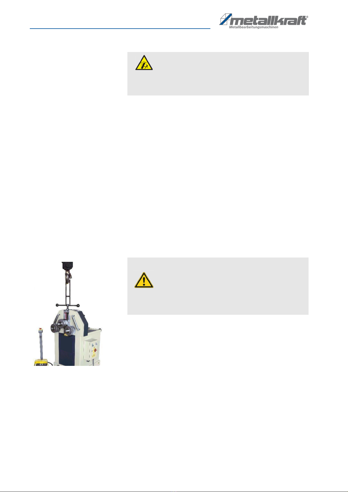
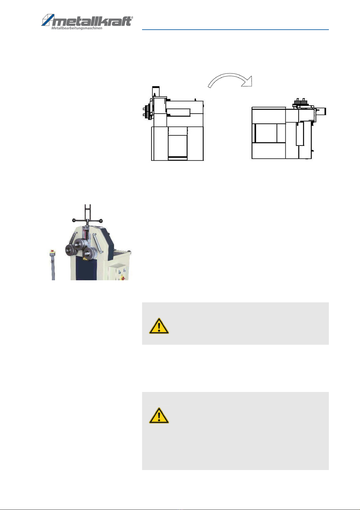
The ring bending machine PRM 35 F can be set p horizontally or vertically for
the machining of workpieces (Fig. 12).
Fig. 12: Ring bending machine PRM 35 F - horizontal and vertical se
To change the machine to the horizontal working position, proceed as follows:
Step 1: Loop a belt or a steel cable with a load capacity of approx. 1 ton aro nd
the spindle for height adj stment of the pper roller.
Step 2: Slowly lift the ring bender sing a forklift or crane.
Step 3: Slowly lower the ring bending machine and p ll it to the horizontal
position with the belt or rope.
Fig. 13: Change ring bending machine
8 Commissioning
ATTENTION!
The belt or steel cable m st not be looped aro nd the shaft
pper roller, it co ld be damaged.
WARNING!
anger due to insufficient qualification of per-
sons!
Ins fficiently q alified persons can not assess the risks
involved in handling the machine and expose themselves
and others to the risk of serio s or fatal inj ries.
- Commissioning and all other work sho ld only be carried
o t by q alified personnel.
- Keep inadeq ately q alified persons o t of the work area.

20 PRM F | Version 1.07 | EN
Commissioning
The ring bending machine has an electric motor. It is important to note that
- the power connection has the same characteristics (voltage, mains fre-
q ency, phase) as the motor,
- the mains voltage of 400 V is sed,
- the selection of cable cross-sections for the s pply cable complies with
the applicable VDE g idelines.
- the direction of rotation of the motor is correct (see arrow on the motor).
WARNING!
anger to life!
There is danger to life if these r les are not followed.
- Never carry o t any work on the machine nder the infl -
ence of alcohol, dr gs or medication and / or in case of fati-
g e or concentration-impairing illnesses.
- The machine may only be operated by q alified personnel.
Wear ear protection!
Wearing safety gloves!
Wear safety shoes!
Wear protective clothing!
NOTE!
Before commissioning, the following m st be observed.
- The mains voltage m st correspond to the voltage specifi-
cations on the rating plate.
- The main switch m st be set to "0".
- The safety devices as well as the protective covers m st be
f nctional.
This manual suits for next models
2
Table of contents
Other Metallkraft Cutter manuals


