Metallkraft UB 10 User manual

UB 10
Instruction Manual
UB 10
Universal bending machine
UB 10

2 UB 10 | Version 2.01
Imprint
Product identification
Universal bending machine Item number
UB 10 3776010
Manufacturer
St rmer Maschinen GmbH
Dr.-Robert-Pfleger-Str. 26
D-96103 Hallstadt/Bamberg
Fax: 0049 (0) 951 96555 - 55
E-Mail: [email protected]
Internet: www.metallkraft.de
Indications regarding the operating instructions
Original instructions
Edition: 28.01.2019
Version: 2.01
Language: English
Author: FL
Indications regarding the copyright
Copyright © 2019 St rmer Maschinen GmbH, Hallstadt,
Germany.
The contents of these operating instructions are the sole
property of the company St rmer.
Passing on as well as copying of this document, the use
and distribution of its content are prohibited if not explic-
itly permitted. Contraventions are liable to compensa-
tion.
Subject to technical modifications and error.
Contents
1 Introduction ............................................. 3
1.1 Coypright ............................................................ 3
1.2 Customer service................................................ 3
1.3 Limitation of liability............................................. 3
2 Safety ....................................................... 3
2.1 Symbol explanation ............................................ 3
2.2 Requirements to staff.......................................... 4
2.3 Personal protective equipment ........................... 4
2.4 General safety instructions ................................. 5
3 Intended Use............................................ 5
3.1 Misuse ................................................................ 6
3.2 Residual risks ..................................................... 6
3.3 Technical condition............................................. 6
4 Technical Data.........................................
5 Transport, packaging, storage............... 7
5.1 Delivery and Transport ....................................... 7
5.2 Packaging........................................................... 7
5.3 Storage ............................................................... 7
Description of the device ....................... 7
7 Assembly ................................................. 7
7.1 Set up ................................................................. 8
8 Work and operation ................................ 8
8.1 Application of the eccentric counter-holder......... 8
8.2 The production of U-shaped tabs ..................... 10
8.3 Production of handles....................................... 11
8.4 The production of pipe supports ....................... 12
8.5
The production of U-shaped tabs and mounting
brackets............................................................. 14
9 Special accessories .............................. 15
9.1 Bending segment for spirals ............................. 15
9.2 Heating pipe bending roll set ............................ 16
9.3 Clamp ............................................................... 16
9.4 Adjustable stop 10-200..................................... 16
10 Care, maintenance and repair............ 1
10.1 Maintenance ................................................... 17
10.2 Repair ............................................................ 17
11
Disposal, recycling of used devices
.... 17
11.1 Decommissioning ........................................... 17
11.2 Disposal of new equipment packaging ........... 17
12 Spare parts .......................................... 18
12.1 Ordering spare parts....................................... 18
13 Spare parts drawing............................ 19
14 Declaration........................................... 20
15 Notes .................................................... 21

Introduction
UB 10 | Version 2.01 3
1 Introduction
You have made a good choice by purchasing the ME-
TALLKRAFT Bending machine.
Read the operating manual thoroughly before com-
missioning the machine.
It gives you information about the proper commissioning,
intended use and safe and efficient operation and main-
tenance of your bending machine.
The operating manual is part of the bending machine
package. Always keep this operating manual in the loca-
tion where your bending machine is being operated. All
local accident prevention regulations and general safety
instructions for the operating range of your bending ma-
chine must also be complied with.
1.1 Coypright
The contents of these instructions are copyright. They
may be used in conjunction with the operation of the de-
vice. Any application beyond those described is not per-
mitted without the written approval of St rmer GmbH.
For the protection of our products, we shall register tra-
demark, patent and design rights, as this is possible in
individual cases. We strongly oppose any infringement
of our intellectual property.
1.2 Customer service
Please contact your dealer if you have questions con-
cerning your Bead bending machine or if you need tech-
nical advice. They will help you with specialist informa-
tion and expert advice.
Germany:
St rmer Maschinen GmbH
Dr.-Robert-Pfleger-Str. 26
D-96103 Hallstadt
Repair service:
Fax: 0049 (0) 951 96555-111
E-Mail: [email protected]
Internet: www.metallkraft.de
Spare part orders:
Fax: 0049 (0) 951 96555-119
E-Mail: [email protected]
We are always interested in valuable experience and
knowledge gained from using the application-which then
could be shared and be valuable to develop our products
even further.
1.3 Limitation of liability
All information and notes in these operating instructions
were summarised while taking applicable standards and
rules, the state-of-the-art technology and our long-term
knowledge and experiences into consideration.
In the following cases the manufacturer is not liable for
damages:
- Non-observance of the operating instructions,
- Inappropriate use
- Use of untrained staff,
- Unauthorised modifications
- Technical changes,
- Use of not allowed spare parts.
The actual scope of delivery may deviate from the expla-
nations and presentations described here in case of spe-
cial models, when using additional ordering options or
due to latest technical modifications.
The obligations agreed in the delivery contract, the gen-
eral terms and conditions as well as the delivery condi-ti-
ons of the manufacturer and the legal regulations at the
time of the conclusion of the contract are applicable.
2 Safety
This section provides an overview of all major safety
pac-kages for personal protection and safe and trouble-
free operation. Further task-related safety instructions
are contained in the individual chapters.The term "ma-
chine" below replaces the usual trade name of the object
to which these operating instructions refer (see cover
sheet).
2.1 Symbol explanation
Safety instructions
The safety notes in these operating instructions are high-
lighted by symbols. The safety notes are introduced by
signal words which express the concern of the risk.
DANGER!
This combination of symbol and signal words indi-
cates an imminently dangerous situation which may
lead to death or severe injury if not avoided.
WARNING!
This combination of symbol and signal words indi-
cates a potentially dangerous situation which may
lead to death or severe injury if not avoided.

4 UB 10 | Version 2.01
Safety
Tips and recommendations
It is necessary to observe the safety notes written in
these operating instructions in order to reduce the risk of
personal injuries and damages to property.
2.2 Requirements to staff
The different tasks described in this manual represent
different requirements to the qualification of the persons
entrusted with these tasks.
Only persons reliable working procedures can be ex-
pected from, are allowed to perform all works. Persons
the responsiveness of which is affected by e. g. drugs,
alcohol or medication, are not allowed to work with the
machine.
The qualifications of the personnel for the different tasks
are mentioned below:
Operator
The operator is instructed by the operating company
about the assigned tasks and possible risks in case of
improper behaviour. Any tasks which need to be per-for-
med beyond the operation in the standard mode must
only be performed by the operator if it is indicated in
these instructions and if the operating company expres-
sively commissioned the operator.
Qualified personnel
Due to their professional training, knowledge and experi-
ence as well as their knowledge of relevant regulations
the specialist staff is able to perform the assigned tasks
and to recognise and avoid any possible dangers them-
selves.
Manufacturer
Certain works may only be performed by specialist per-
sonnel of the manufacturer. Other personnel is not au-
thorized to perform these works. Please contact our cus-
tomer service for the execution of all arising work.
2.3 Personal protective equipment
The personal protective equipment serves to protect per-
sons against impairments of safety and health while wor-
king. The staff member has to wear personal protec-tive
equipment while performing different tasks on and with
the machine which are indicated in the individual para-
graphs of these instructions.
The personal protective equipment is explained in the
following paragraph:
CAUTION!
This combination of symbol and signal words indi-
cates a potentially dangerous situation which may
lead to slight or minor injury if not avoided.
NOTE!
This combination of symbol and signal words indi-
cates a potentially dangerous situation which may
lead to material or environmental damage if not avoi-
ded.
Tips and recommendations
This symbol highlights useful tips and recommenda-
tions as well as information for an efficient and trou-
ble-free operation.
WARNING!
Danger in case of insufficient quali-
fication of the staff!!
Insufficiently qualified persons cannot estimate the
risks while using the vacuum cleaner and expose
themselves and others to the danger of severe or let-
hal injuries.
- Have all works only performed by qualified persons.
- Keep insufficiently qualified persons out of the work-
ing area.
Eye protection
The goggles protect the eyes from flying parts and
liquid splashes.
Protective gloves
The protective gloves serve to protect the hands
against sharp components as well as against fric-
tion, abrasions or deep injuries.
Safety boots
Safety boots protect the feet from being crushed, fall-
ing parts and slipping over on slippery ground.
Protective clothes
Protective clothes are made of a tightly fitted fabric
without the protruding parts of low tear strength.

Intended Use
UB 10 | Version 2.01 5
2.4 General safety instructions
Please note the following:
- Use the guards and secure them securely. Never work
without guards and get them working.
- Always keep the machine and its working environment
clean. Ensure adequate lighting.
- The universal bending machine must not be modified in
design and should not be used for purposes other than
those foreseen by the manufacturer.
- Never work under the influence of concentration-distur-
bing illnesses, fatigue, drugs, alcohol or medicines.
- Keep children and persons not familiar with the Univer-
sal Bending Machine away from their work environ-
ment.
- Eliminate disturbances that affect safety immediately.
- Protect the universal bending machine from moisture.
- Before each use of the Universal Bending Machine,
make sure that no parts are damaged. Damaged parts
must be replaced immediately to avoid any danger.
- Do not overload the universal bending machine! You
work better and safer in the specified performance
range. Use the right tool! Make sure the tools are not
dull or damaged
- Only use original spare parts and accessories to avoid
possible dangers and accident risks.
- To avoid injury from crushing, pay attention to the shea-
ring edges during transport, cleaning and when using
the machine.
- Always make sure that you never get any body parts
into the bending area when using the machine.
- Avoid unnatural posture and maintain balance at all
times. Wear work shoes to increase their stability.
- If you pass on this bending machine, you must hand
over all the tools and documents supplied with the ben-
ding machine.
- Due to the forces occurring during the forming process,
the machine must be firmly connected to the ground to
absorb the reaction forces.
- Before and during work, check the work area so that
there are no unauthorized persons in it. Do not allow
the bending machine to be touched by other persons,
especially children.
- Maintain the machine with care. Keep the bending ma-
chine clean in order to be able to work well and safely in
the long term. Follow the instructions for maintenance.
- Remove oil and grease residues from the handle and
keep it dry.
- Observe the maximum dimensions of the workpieces
given in the technical data
- Before starting the bending machine work, find out
about the type of material to be processed.
- Do not overload the bending machine. It works better
and safer in the specified field of application.
- Check the stability of the machine and, if necessary,
the secure screw connection with the foundation.
- Please note that the use of other tools and other acces-
sories may result in injury to you.
- Always work on only one workpiece.
- Damaged machine parts must be replaced or repaired
as intended by a recognized specialist workshop.
- Make sure that only original spare parts are used du-
ring repairs. Otherwise, the operator is at risk of acci-
dents.
3 Intended Use
The universal bending machine is suitable for bending
flat, rectangular and round sections and for heating pi-
pes. A rational way to bend usual shapes and curves.
The machine is light enough and can be carried to diffe-
rent workplaces.
The compact dimensions of the Universal Bending Ma-
chine UB 10 ensure easy handling. It is suitable for both
private and commercial use.
Proper use also includes compliance with all information
in this manual. Any use beyond the intended use or
otherwise is considered misuse.
WARNING!
The improper use of this device as well as the disre-
gard of the safety instructions or operating instructi-
ons in the operating instructions exclude any liability
of the manufacturer for resulting damage to persons
or objects.
WARNING!
Danger in case of misuse!!
Misuse of the universal bending machine can lead to
dangerous situations.
- Only operate the Universal Bending Machine in the
performance range specified in the technical data.
- Never bypass or override the safety devices.
- Only operate the Universal Bending Machine in a
technically perfect condition.

6 UB 10 | Version 2.01
Technical Data
3.1 Misuse
If the intended use is observed, no reasonably foresee-
able misuse is possible, which could lead to dangerous
situations with personal injury.
3.2 Residual risks
Even if all safety regulations are observed and the ma-
chine is used correctly, there are still residual risks listed
below:
- There is a risk of injury to the upper limbs (e.g., hands, fin-
gers).
- Danger from falling workpieces
- Danger of pulling in clothes and objects.
- During set-up and set-up work, it may be necessary to dis-
mantle on-site protective equipment. This creates various
residual risks and potential dangers that every operator
must be aware of.
3.3 Technical condition
The Universal Bending Machine UB 10 complies with the
current state of the art in design and execution and is
built according to the recognized safety rules.
Please note the following:
- Before each use, the machine should be checked
for externally visible damage.
- During each use, the operating behavior is obser-
ved.
- In the event of safety-relevant deviations from the
delivery condition, the machine must be inspected by
an authorized specialist and, if necessary, repaired.
- From the point in time when the machine no longer
meets the normal operating conditions, the bending
machine must be taken out of service until repaired.
3.3.1 Machine operation
The bending machine can be dangerous if it is not used
in accordance with the chess and intended purpose.
In addition to the health and safety instructions in this
operating manual, the generally applicable safety and
accident prevention regulations for protection against the
risk of injury must be observed and adhered to.The work
instructions in the individual chapters of the operating in-
structions must be followed. The safety instructions must
be observed under all circumstances. Despite observing
all working instructions, safety and accident prevention
regulations, there remains a residual risk when handling
the machine. Through concentrated and forward-looking
work and action, you can reduce the residual risk.
4 Technical Data
Scope of delivery:
- Bending rollers: 2 x Ø 24/30/37/43/49/62/75 mm
Optional accessories:
- Heating pipe bending roller set
Item number: 3790001
- Bending roller set 10-180
Item number: 3790002
- Adjustable stop 10-200
Item number: 3790003
- Clamping plate
Item number: 3790004
- Conversion kit for UB 10 to RB 30
Item number:3790006
- Helical bending element UB 11
Item number:3790011
-
Separate holding handle for helical bending element UB 11
Item number: 3790280
DANGER!
The machine may only be operated in a technically
perfect condition. Any faults must be eliminated im-
mediately.
DANGER!
Unauthorized modifications or changes, especially
those that affect the safety of the machine operator,
are generally prohibited. Technical changes, conver-
sions and extensions made by the user on the ma-
chine may void the machine's operating license and
are the responsibility of the operator.
ATTENTION!
In the interest of further technical development or
changing regulations, the manufacturer reserves the
right to make changes to the characteristics of the
product at any time without prior notice.
Technical Data UB 10
Pipes G 3/4 "
Weight 32 kg
Flat steel: plate rolling 10 x 50 mm
Flat steel: acute bending 6 x 50 mm
Round materials Steel/Aluminium/Copper
16 mm
Round materials stainless steel
14 mm
Square materials Steel/Aluminium/Copper
16 x 16 mm
Square materials stainless steel 14 x 14 mm

Transport, packaging, storage
UB 10 | Version 2.01 7
5 Transport, packaging, storage
5.1 Delivery and Transport
Delivery
Check the Machine on delivery for any visi-ble transpor-
tation damage. If you notice any damage to the device
please report this immediately to the carrier or dealer.
Transport
Remove the factory-prepared antirust agent with thinner
or paint remover before installing the device. Then lubri-
cate with machine oil. Make sure that the device is not
set up or put into operation in a damp or wet environ-
ment. The humidity should not exceed 60% and the
measured room temperature should be between max. 0
° C and 40 ° C amount. .
5.2 Packaging
All used packaging materials and packaging aids are re-
cyclable and should be taken to a materials recycling de-
pot to be disposed of.
The delivery packaging is made of cardboard, so please
dispose carefully by having it chopped up and given to
the recycling collection
The film is made of polyethylene (PE) and the cushioned
parts of polystyrene (PS). Deliver these substances to a
collection point for recyclable materials or to the waste
disposal company which looks after your region.
5.3 Storage
Thoroughly clean the Universal Bending Machine in a
dry, clean and frost-free environment.
The universal bending machine must not be parked in a
room with chemicals.
If the machine is stored for a long time, all bare metal
parts must be greased against rusting.
6 Description of the device
Illustrations in this operating manual serve the gene-
ral understanding and may deviate from the actual
design.
Fig. 1: Description of the device
7 Assembly
Please note the following:
- Make sure that all bolts are inserted correctly and
in the proper place.
Fig. 2: Assembly
NOTE!
For a safe stand, it is recommended to attach the de-
vice to a stable and stable surface using the holes pro-
vided on the bottom of the device.
Adjusting pin
Bending
arm
Eccentric counterholder
Bending
unit
bending
rollers for
round
material
Frame
Bending rollers for flat
material

8 UB 10 | Version 2.01
Work and operation
1 screw
2 screw
3 Nut
4 spacer tube
5 spacer ring
7.1 Set up
Mount the machine firmly on the ground at a suitable
location.
Note the following:
• Make sure you have enough space around the ma-
chine (see Fig. 3).
• Make sure that the bending machine is firmly screwed
to the floor.
Fig. 3: Set up example
8 Work and operation
Information about the use of the machine
• Do not bend other steels than standard structural steel.
(8 x 50 mm and round steel up to Ø16 mm, rectangular
steel up to a size of 14 x 14 mm and heating pipes up to
a size of G3 / 4˝!
• Do not bend materials thicker than 6 mm around the
center pin. Always use the Ø24 mm rollers to prevent the
bolt from bending.
• Do not use additional lever extension.
• Do not use the right-angle bending accessory to bend
wooden blocks.
• When using the right angle bend accessory, bend only
standard steel up to 6 x 50 mm or 7 x 30 mm.
• Keep the work area around the machine clean to avoid
unnecessary accidents.
• Preventing the bending roller from dropping suddenly
could cause serious injury.
• When shearing, edging and bending, you can mount a
rip fence. To do this, screw the guide pins of the rip fence
to the frame.
8.1 Application of the eccentric counter-holder
This counterholder in the bending arm ensures that the
material is firmly clamped during the bending process.
Fig. 4: Counter-holder
The eccentric anvil offers four positions. Always use the
proper position to bring the anvil as close as possible to
the center pin or roller, but make sure that a small gap is
left for the material.
To reach two of the four positions, the anvil must rotate
from side to side. If the hole is to the left of the center, the
backstop will slip and thus the material will. If you are
using a large bending roller, insert the counterholder and
stop into the corresponding hole so that the material is
firmly attached. Place the anvil as close to the central
bolt or to the bending roller as possible and turn the anvil
into one of the four positions. You can adjust the stop on
the support plate by one hole forward or backward to
achieve the required clearance.
Too large a distance between the central bolt or the ben-
ding roller and the stop causes the slipping of the mate-
rial and thus an inaccurate bending radius.
If a very accurate bend radius is desired, it is prudent to
secure the material with a retainer clip against the anvil
to prevent the material from slipping.
Wall

Work and operation
UB 10 | Version 2.01 9
Fig. 5: Centering the counter-holder
In most cases it is not necessary to use a retaining clip
when using an anvil. However, you can use a holder
clamp, if you want to make special curvatures.
Fig. 6: Right Position of the counterholder
Examples of the eccentric counterhold for each "correct"
position:
Position 1
Bender for flat material or round material of mm: Ø
37 m
Fig. 7: Example Position 1
Position 2
Bender for flat material or round material of mm: Ø
75 mm
Fig. 8: Example Position 2
Position 3
Flat or round material of mm: use central bolt
Fig. 9: Example Position 3

10 UB 10 | Version 2.01
Work and operation
Position 4
Rectangular or round steel of 1 mm: Use Ø 30 mm
bending roller
Fig. 10: Example Position 4
Application of right-angle bending accessory
Fig. 11: Application of the bending accessory
If you want to bend a right angle, mark the location of the
sheet with chalk. When inserting the material into the
bending machine, make sure that the marked area is still
partially visible. The bending edge of the right-angle ben-
ding accessory covers the other side of the marked loca-
tion.
If two right angles are to be bent on the same flat mate-
rial (eg 5 x 25 mm), the marked points must be separa-
ted by 3 mm more than the required inner dimension. If
the material thickness is different, the corresponding
bending allowances must be taken into account
If very precise work is needed, first bend a specimen be-
fore bending a large amount. So you can find out if you
need to move the spot or if you need to lengthen or shor-
ten the material.
This instruction manual specifies the bending measure,
but if you are unsure about the dimensions, it is better to
use a narrower material than the required thick material,
which would be more expensive. If you are sure about
the bending and bending degree, make a note of it for
further use.
Fig. 12: Application of the bending accessory
The adjustable stop is used for equal curvatures. Make
sure that the screw is tight and that the stopper is tight.
Fig. 13: Chalk mark
This image shows the exact position of the chalk mark against
the bending edge of the right-angle bending accessory.
8.2 The production of U-shaped tabs
Preparing the material - The length of the material for U-
shaped tabs must be cut according to the size of the
bending element.
The holes in the carrier plate
The number of the hole in which the ex-centric counter-
holder is placed.
Fig. 14: Holes of the carrier plate

Work and operation
UB 10 | Version 2.01 11
The position of the eccentric counter-holder
The correct position of the counter-holder, according to
the thickness of the material to form U-shaped tabs.
Fig. 15: Position of the counter-holder
The distance to the eccentric counterholder
Before bending the material, measure the distance from
the eccentric anvil.
Fig. 16: Distance to the anvil
Bending roller
It is used in the bending fork.
The holes in the bending arm
The various holes in the bend of the bend arm show
where the bolt is placed to hold the bend roll.
Fig. 17: Holes in the bending arm
8.3 Production of handles
Round material
With the bending machine you can produce handles with
different shapes and sizes. Each of the three illustrated
handles has been bent by Ø 15 mm and a length of 230
mm steel. After bending the bends, drill a Ø 15 mm hole
in the tab. Then insert the handle into the tab and weld it
tight. Sand the rest off the tab to get a flat surface.
The correct position of the eccentric counter-holder is gi-
ven by the diameter of the material (see picture on the
right). After you have made the first bend, you must turn
the material 90 ° and bend the other end 90 °.
Fig. 18: Production of handles
Flat material
Chalk the workpiece as shown in the picture. The mar-
kings on the ends must be on one side of the material,
the inside on the other side.
The dimensions in the illustration can be replaced by
others. Depending on the user's idea of the universal
bending machine.
Fig. 19: Production of handles with flat material
1. Curvature
Insert a flat material up to the mark (1) and bend it by 90
°. Check the angle before proceeding. Attach the eccent-
ric counterhold so that the respective angles are 90 °.
Distance
NOTE!
When using a different diameter material for the hand-
le, the diameter of the hole in the tab must be identical
to the diameter of the handle.

12 UB 10 | Version 2.01
Work and operation
Fig. 20: Curvature 1
2. Curvature
Turn the material and insert it to the mark 2. Again, turn a
90 ° angle here.
Fig. 21: Curvature 2
3. Curvature
Turn over the half-finished product and place it in the de-
vice up to mark 3. Bend another 90 ° angle.
Fig. 22: Curvature 3
4. Curvature
Turn the half finished product over and repeat step 3.
Fig. 23: Curvature 4
8.4 The production of pipe supports
Fig. 24: Manufacturing pipe clamp
1.Curvature
Put the eccentric anvil in position Then insert the mate-
rial into the bending machine as in the picture. Use the
manual lever to bend the material until the bender roller
reaches the material end.
Fig. 25: Curvature 1
Pipe clamp

Work and operation
UB 10 | Version 2.01 13
2. Curvature
Insert the right angle accessory. Insert the product so
that the curvature lies on the bolt. Insert the stop into
hole 6 (clockwise). Now bend the material with the lever,
so that the lever is about 3 mm from the bolt.
Fig. 26: Curvature 2
Attach the retaining clip to the end of the stopper to pre-
vent the material from slipping.
You can also make many other types of clamps. Write
down the work steps for the different types of clamps.
This will help you later if you want to make it again.
Fig. 27: Production double pipe clamp
1. Curvature
Insert the material into the bender as shown in the
picture. Use the lever to bend it until the bender roller re-
aches the end of the material.
Fig. 28: Curvature 1
2. Curvature
Turn over the half-finished product and place it in the
bending device. (See image). Now take the lever and
bend the material until the bending roller reaches the end
of the material.
Fig. 29: Curvature 2
3. Curvature
Attach the right angle attachment. Now insert the mate-
rial as far as possible into the bending device, so that it
leans against the central bolt. (You must take out the
central bolt). Insert the stop in hole 6 clockwise. Move
the bending lever so far that it is approx. 3 mm away
from the stop.
Fig. 30: Curvature 3
4. Curvature
Turn the half-finished product over to the other end. Now
insert the material as far as possible into the bending de-
vice, so that it leans against the central bolt. (You must
take out the central bolt again). Now bend the material.
The lever must be 3 mm away from the stop.
Fig. 31: Curvature 4
Pipe clamp
14 UB 10 | Version 2.01
Work and operation
8.5 The production of U-shaped tabs and
mounting brackets
Before you start making U-shaped tabs, try bending a
pattern first. Check all sizes and make the necessary
changes.
Fig. 32: Finishing U-shaped tabs
Always move the eccentric anvil so that it is as close to
the bolt or bender as possible to prevent the material
from slipping.
If you want to extend the U-shaped tab, you will first find
out how much material you need for it. Now you have to
add twice the amount.
Example: If you want to extend the tab by 25 mm, you
must add 50 mm over the total length. The distance from
the eccentric anvil to the material end will only increase
by 25 mm. The other 25 mm are for the other end. The
bending machine has bending rolls of different sizes.
This allows you to bend different U-shaped tabs. Always
use rollers on the center bolt when working with a mate-
rial thicker than 9 mm. Otherwise you could accidentally
bend the bolt. The material is stretched during the ben-
ding process. This stretch is different for each material.
For this reason, we recommend that you test the stretch
even if you use this manual.
Make a note of the diameters of the bending rolls and the
dimensional deviation of the elongation. So you can save
time in a repeated production.
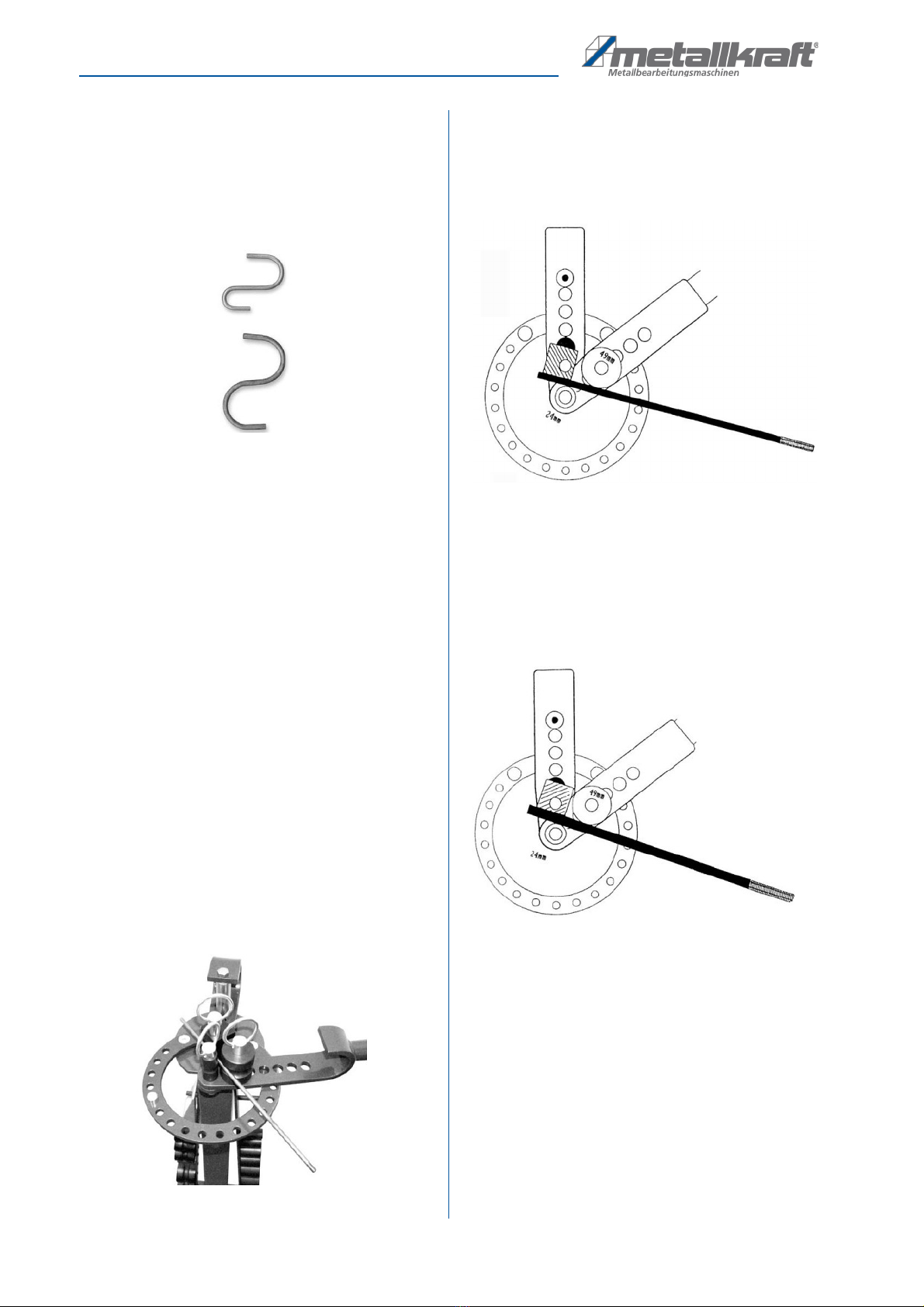
Fig. 33: Correct arrangement
Example 1
For a 9 mm screw with a length of 310 mm, the distance
from the eccentric anvil to the stop is 2.15 mm.
Fig. 34: Example 1
Example 2
For a screw with a length of 310 mm and a thickness of
12 mm, the distance from the eccentric counter-holder to
the stop is 1.15 mm.
Fig. 35: Example 2

Special accessories
UB 10 | Version 2.01 15
Example 3
For screws with a length of 315 mm and a thickness of
15 mm, the distance from the eccentric anvil is 6 mm.
Fig. 36: Example 3
The sizes given here are suitable for making 250 mm
long screws. However, you can always vary the length
by simply shortening or lengthening the length. You can
also change the length of the material after curvature by
reducing or extending the length of the eccentric anvil.
Make sure that a sufficient length of material leans
against the counterholder.
9 Special accessories
9.1 Bending segment for spirals
The bending segment is supplied as a separate acces-
sory and can bend a hot rolled material of 5 x 25 mm.
The edge of the segment bends the material in a spiral. If
you want to make several spirals of the same shape,
mark the top of the bend segment where the first spiral
stops. If you bend the other spirals up to this mark, the si-
zes of the spirals will all be the same.
Fig. 37: Bending segments for spirals
By bending large and small spirals, you must first insert
the fence and the bend segment into hole 2.
Fig. 38: Insert stop
If you would like to produce a large spiral after the first
phase of bending, remove the stop of the bending seg-
ment from hole 2 and insert them into hole 5 (at the very
end).
Fig. 39: Making a big spiral
Do not bend a large spiral when the fence and bend seg-
ment are in hole 5. You need to start with it when in hole
2, otherwise the spiral will not be formed properly.
Fig. 40: Produce a big spiral

16 UB 10 | Version 2.01
Care, maintenance and repair
Turn the spiral around as long as the bending segment
allows it. Take out the stop and the segment and place
them in the hole for the second bend and finish the spiral.
9.2 Heating pipe bending roll set
For cold bending of heating pipes of size G3 / 8 ", G1 /
2", G3 / 4 ". For a curvature of a heating pipe, a heating
pipe bending roll set is required (larger and smaller rolls).
The large roll is used as the middle and the material is
bent with it. The procedure is similar to the normal ben-
ding rollers.
Fig. 41: Heating tube bending rolls set
9.3 Clamp
It is used for mounting the dismantled bending unit of the
UB 10. For this you need three screws. The clamping
plate must be firmly mounted to an anchored workbench.
Fig. 42: Clamp
9.4 Adjustable stop 10-200
It is a universal, adjustable stop to produce material of the
same length for a series of bends. Use a screw and a nut
to secure the fence in the second or third hole.
Then turn the stopper so that the curved material is per-
pendicular to the outer side of the stopper. Fix the stopper
so that the material is parallel to the underside of the stop-
per. The adjustable stop can be fixed from both sides.
Fig. 43: Adjustable stop
10 Care, maintenance and repair
NOTE!
The pipe must not be bent more than 180 °, other-
wise it will jam in the bending roller.
Tips and recommendations
To ensure that the bending machine is always in
good operating condition, regular care and main-
tenance work must be carried out.
DANGER!
Danger due to insufficient qualifica-
tion of persons!!
Insufficiently qualified persons can not assess the
risks involved in maintenance work on the machine
and expose themselves and others to the risk of
serious injury.
- All maintenance work should only be carried out by
qualified persons.
NOTE!
Before servicing and maintenance the Universal
Bending Machine, the maintenance instructions must
be carefully read. The handling of the Universal Ben-
ding Machine is only permitted to persons who are
familiar with the Universal Bending Machine.
DANGER!
After servicing, maintenance and repair, check that all
panels and guards are properly installed on the machine
and that there is no more tool inside or in the working
area of the universal bending machine. Damaged safety
devices and equipment must be repaired or replaced by
the customer service.

Disposal, recycling of used devices
UB 10 | Version 2.01 17
10.1 Maintenance
General informations:
- Check the universal bending machine for damage
before and after each use.
- All moving parts must be lubricated at regular inter-
vals. Use only acid-free lubricants.
- Do not clean the universal bending machine with
aggressive chemicals, but only with a dry cloth.
- Do not store the universal bending machine outs-
ide and protect it from high humidity, cold or heat.
- The machine clean and the warehouse seats and
work surfaces of the work.
10.2 Repair
If the bending machine does not work properly, contact a
dealer or our customer service. The contact details can
be found in chapter 1.2 Customer Service.
11 Disposal, recycling of used devices
Please take care in your own interest and in the interest
of the environment that all component parts of the ma-
chine are only disposed of in the intended and permitted
way.
11.1 Decommissioning
Disused equipment must be taken out of service immedi-
ately in order to avoid later misuse and endangering the
environment or people.
- Dispose of all environmentally hazardous fluids from
the old device.
- If necessary, disassemble the machine into manage-
able and usable assemblies and components.
- Supply the machine components and operating materi-
als to the appropriate disposal channels.
11.2 Disposal of new equipment packaging
All packaging materials and packaging aids used in the
machine are recyclable and must always be recycled.
The packaging wood can be sent for disposal or recy-
cling.
Packaging components made of cardboard can be crus-
hed for waste paper collection.
The films are made of polyethylene (PE) or upholstery
parts made of polystyrene (PS). These substances can
be reused after reprocessing if they are forwarded to a
recycling center or to the disposal company responsible
for them.
Only pass on the packaging material sorted, so that it
can be directly recycled.
ATTENTION!
To avoid injuries caused by crushing, pay attention
by shearing edges during transport, cleaning and
when using the device.
NOTE!
Oil and grease cleaning agents are hazardous to the
environment and must not be disposed of in waste-
water or normal household waste. Dispose of these
funds in an environmentally friendly way. The
cleaning cloths soaked in oil, grease or detergent are
easily combustible. Collect them in a suitable, closed
container and dispose of them in an environmentally
friendly way - Do not throw in the trash!
DANGER!
Repair work may only be carried out by qualified per-
sonnel.

18 UB 10 | Version 2.01
Spare parts
12 Spare parts
12.1 Ordering spare parts
The spare parts can be obtained from the dealer or directly
from the manufacturer. The contact details are in chapter
1.2 Customer Service. Specify the following key data when
inquiring or ordering spare parts:
- Type of device
- Item No.
- Position No.
- Year of construction:
- Quantity
- Required mode of dispatch (mail, freight, sea, air,
express)
- Address of dispatch
Spare part orders which do not include the above indica-
tions may not be taken into consideration. If the indica-ti-
ons regarding the mode of dispatch are missing, the pro-
duct is dispatched at the discretion of the supplier.
You will find information regarding the device type, item
No. and year of manufacture on the type plate fixed to
the Machine.
Example
The bending additive for the universal bending machine
UB 10 has to be ordered. This is indicated in the spare
parts drawing with the item number 010-070.
- Type of device: Universal bending machine
- Item number: 377 010
- Position number: 010-070
Your order number is: 0-377 010-010-070
The order number consists of the item number, the posi-
tion number and one digit in front of the item number (0).
- Place the digit 0 in front of the item No.
- Also place the digit 0 in front of the position No. 1
trough 9.
DANGER!
Risk of injury due to incorrect spare
parts!
The use of incorrect or faulty replacement parts may
cause danger to the operator and cause damage and
malfunction.
- Only original spare parts from the manufacturer or re-
placement parts approved by the manufacturer must be
used.
- In case of doubt, always contact the manufacturer.
NOTE!
Using non-approved spare parts voids the manu-
facturer's warranty

Spare parts drawing
UB 10 | Version 2.01 19
13 Spare parts drawing
In case of service, the following drawing shall help to identify the necessary spare parts. If necessary, send a copy of the
parts drawing with the marked components to your authorised dealer.
Fig. 44: Spare parts drawing UB 10

20 UB 10 | Version 2.01
Declaration
Manufacturer / distributor: St rmer Maschinen GmbH
Dr.-Robert-Pfleger-Str. 26
D-96103 Hallstadt
The universal bending machine is a hand-operated machine and is not subject to harmonized standards in
the sense of the regulations for CE certification. Therefore, the creation of a CE declaration and a
corresponding marking are not necessary.
Product group: Metallkraft® Metal working machines
Designation of the machine: UB 10
Machine type: Universal bending machine
Item number: 3776010
Serial number: ___________________
Year of manufacture: 20____
The designated product complies with the following regulations:
Applied national standards and technical specifications:
the regulations valid until now in Germany directory index machines October 92 to the GSG
e.g. VDI 2854, VBG 1, VBG 5
Responsible for documentation: Kilian St rmer, Dr.-Robert-Pfleger-Str. 26, D-96103 Hallstadt
Hallstadt, 06.05.2007
______________________
Kilian St rmer
General Manager
14 Declaration
Table of contents
Other Metallkraft Cutter manuals


Popular Cutter manuals by other brands


METALpro
METALpro MP9500 Operation manual

Cricut Expression
Cricut Expression 24" Personal Electronic Cutter user manual

REMA
REMA KS 100 INSTRUCTIONS MANUAL AND SERVICE INSTRUCTIONS

Globe
Globe GFP500 instruction manual

Jula
Jula Meec tools B-850 operating instructions

practyl
practyl 450ETC1-18031.1 instruction manual


