Metasys CH Series User manual

Fire Initiating Devices and Notification Appliances Technical Manual 408
Notification Appliances Section
Technical Bulletin
Issue Date 1095
© 1995 Johnson Controls, Inc. 1
Code No. LIT-408175
Introduction Page 3
●
General Description 3
Installation Procedures 11
●
Mounting 12
●
Wiring Installation Guidelines 17
●
Limitations 24
CH Series Chimes and Strobe Chimes

2 Notification Appliances—CH Series Chimes and Strobe Chimes

Notification Appliances—CH Series Chimes and Strobe Chimes 3
Introduction
The CH series electronic chimes and strobe chimes are
UL Listed under Standard 1971 for signaling devices for the hearing impaired and UL
Standard 464 for private mode signal appliances. The CH series chimes and strobe
chimes are manufactured by Wheelock for use with Johnson Controls systems. All inputs
are compatible with standard reverse polarity supervision of circuit wiring by a Fire
Alarm Control Panel (FACP).
CH series strobe chimes incorporate a xenon flashtube with solid-state circuitry enclosed
in a rugged LEXAN®lens to provide maximum reliability for effective visible signaling.
The strobe chimes are available with a choice of four UL 1971 Listed strobe options:
series LS, LSM, MS, and IS. All models are UL Listed for indoor use. The LS, MS, and
IS models are listed for ceiling or wall mount. The LSM models are listed for wall mount
only, using the backboxes specified in this document. (See the Mounting section of this
document.)
All models offer a choice of single-stroke or vibrating operation, have an adjustable
sound level to 83 dBA (anechoic) at ten feet, and have a chime tone adjustable from 800
to 1200 Hz.
CD-C
ch_1
2-7/16 in.
13/32 in.
3-3/8 in. s
q
.
FIRE
7-3/8 dia.
CH-D
3-3/8 in. s
q
.
5-3/8 in. s
q
.
F
I
R
E
2-7/16 in. 3/8 in. 3 in.
3 in.
Figure 1: CH Series Dimensions
Note: In order to ensure proper operation, this product should be applied as specified
in the applicable National Fire Protection Association (NFPA) codes and in
compliance with its UL listing.
!
WARNING: Personal injury hazard. Failure to follow these directions
may result in the failure of the device to report an alarm or
trouble condition.
Johnson Controls is not responsible for devices that have been improperly installed,
tested, or maintained by others.
General
Description

4 Notification Appliances—CH Series Chimes and Strobe Chimes
All models are UL Listed for indoor use with a temperature range of
32 to 120°F (0 to 49°C) with a maximum relative humidity of 85%.
The chimes and strobe chimes are designed for use with either filtered (regulated) or
unfiltered (unregulated) Full-Wave Rectified (FWR) input voltage. Performance ratings
are based on nominal input voltages
12 VDC (10 to 15.6 VDC) or 24 VDC (20 to 31 VDC).
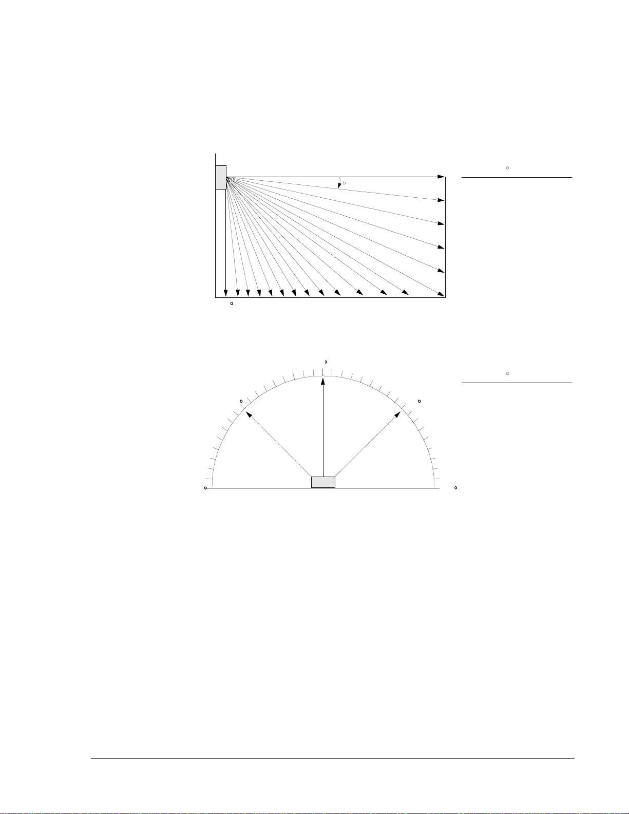
All strobe models are designed to flash as specified with continuous nominal applied
voltage. The flash rate for the strobe is approximately one flash per second at nominal
voltage. Strobes are not designed to be used on coded systems in which the applied
voltage is cycled on and off.
All candela (cd) ratings represent effective intensity based on UL 1971.
This equipment has been tested and complies with the limits for a Class B digital device,
pursuant to Part 15 of the FCC rules. These limits are designed to provide reasonable
protection against harmful interference in installations. This equipment generates, uses,
and radiates radio frequency energy. If not installed and used in accordance with the
instructions, this equipment may cause harmful interference to radio communications.
However, there is no guarantee that interference will not occur in a particular installation.
If this equipment does cause harmful interference to radio or television reception, which
can be determined by turning the strobe and/or audible equipment off and on, the user is
encouraged to try to correct the interference by one or more of the following measures:
1. Reorient or relocate the receiving antenna.
2. Increase the separation between the equipment and receiver.
3. Consult the dealer or an experienced radio/TV technician for help.
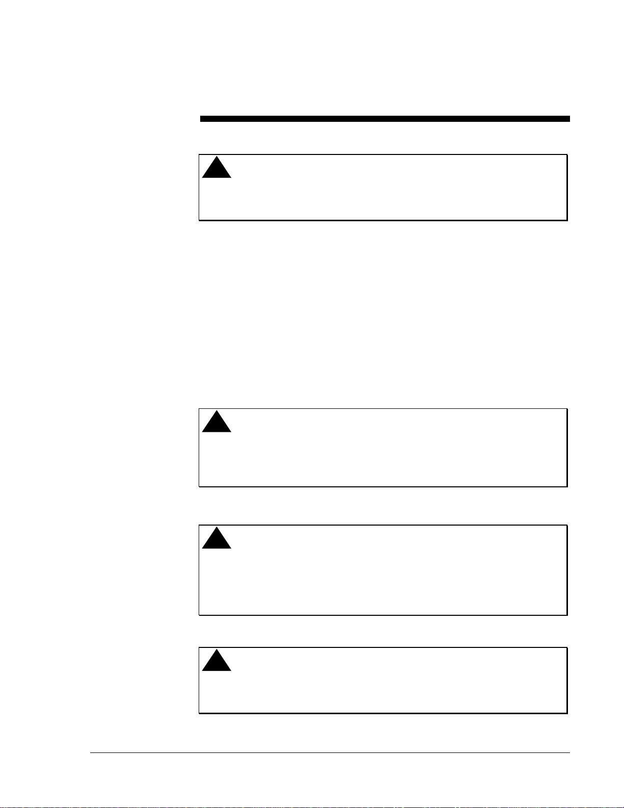
!
CAUTION: Equipment damage hazard. Although UL testing has
verified these products function at 80% of their minimum
rating and 110% of their maximum rating, Johnson Controls
recommends that the voltage applied to these products be
within their rated input voltage range. The application of
improper voltage may result in degraded operation or damage
to these products.
To verify that the signaling device is operating at rated voltages, determine the voltage
drop caused by the resistance of the Notification Appliance Circuit (NAC) wiring. Then,
subtract this voltage from both the maximum and minimum power supply and battery
voltages.
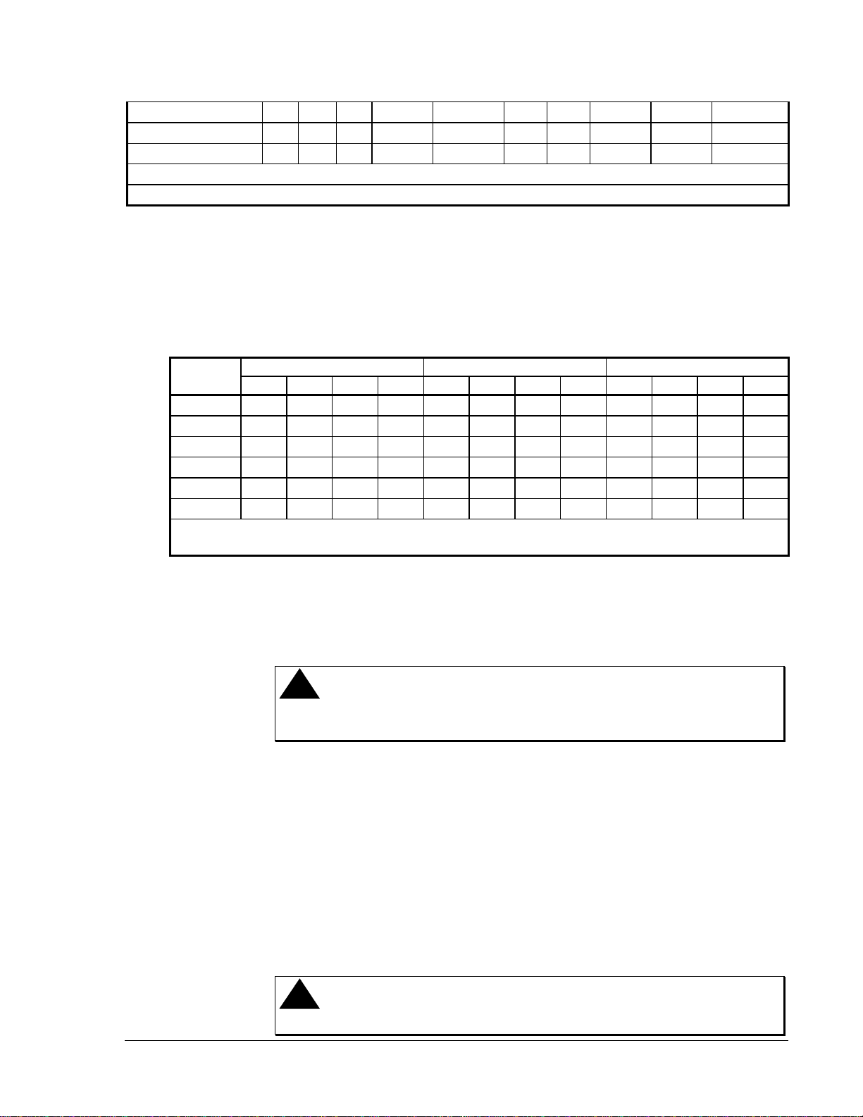
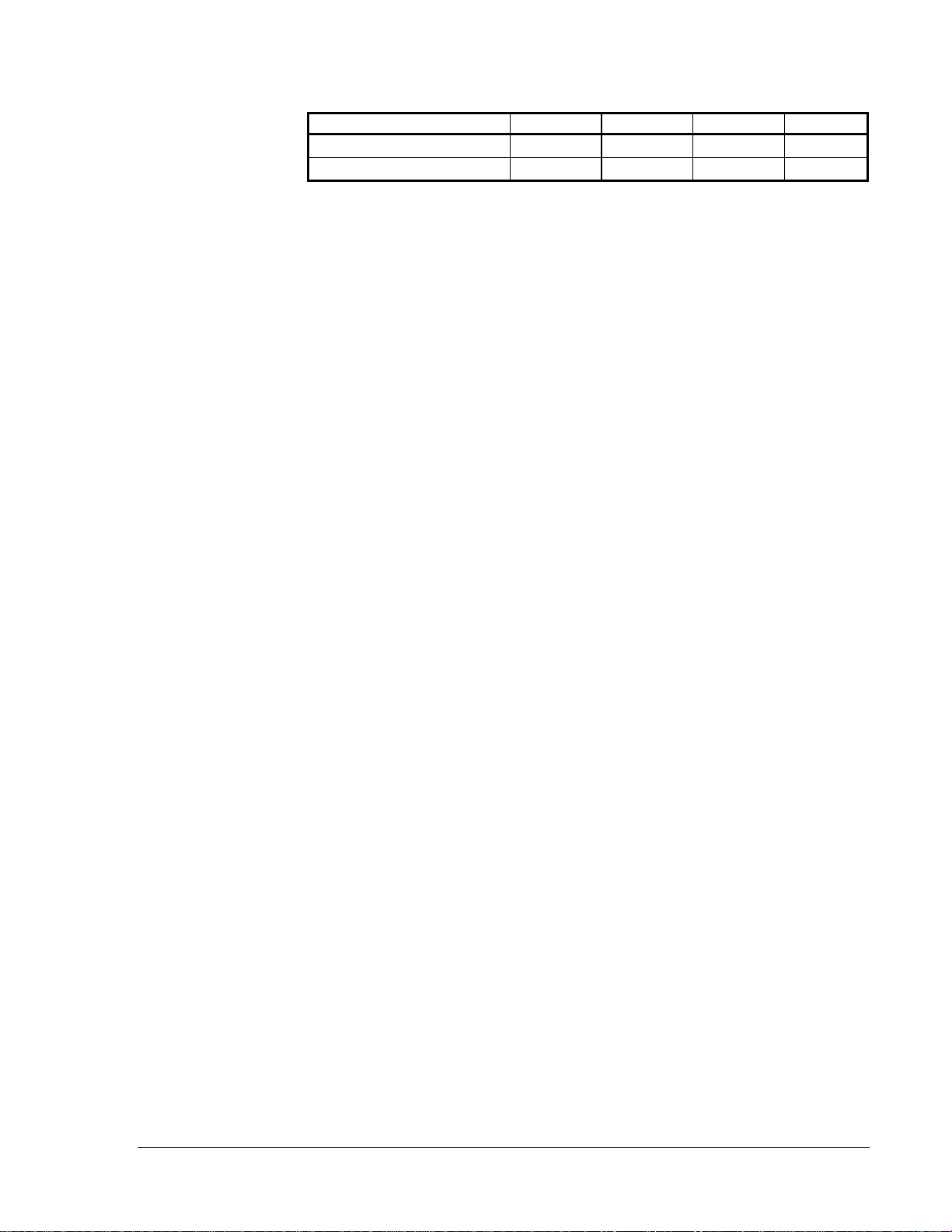
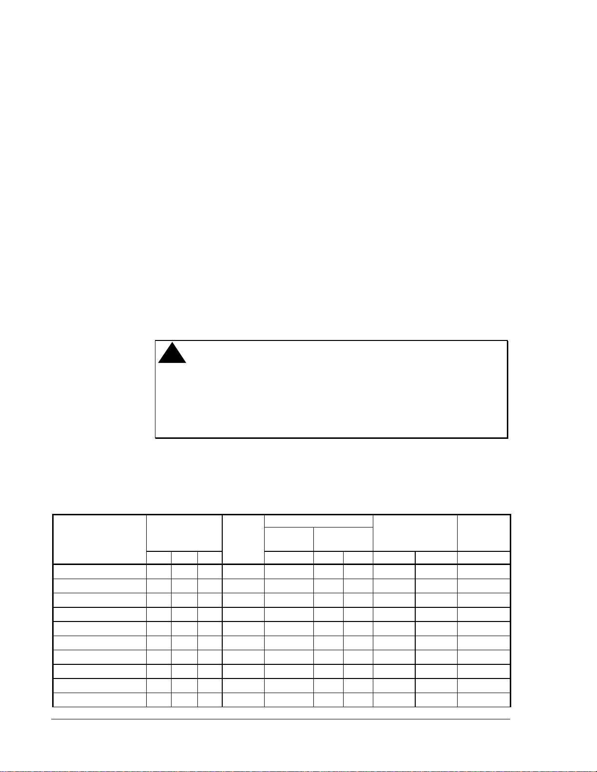
Table 1: CH Series Chimes and Strobe Chimes Specifications
Rated Input Strobe dBA at 10 Feet Rated Average
Model
Number Voltage
(VDC) Candela
(cd) Peak
Anechoic Per UL 464
Reverberant Current for Chime
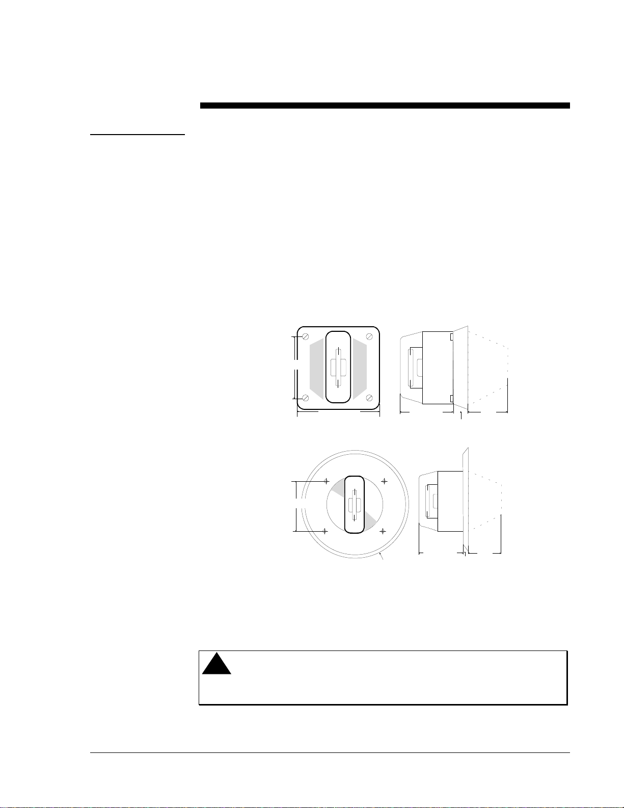
(amperes) Mounting
Options**
Min Nom Max Nom Min Max Nom Max
CH-BF2-R 10 12 15.6 –– 80 52 58 0.020 0.22 D
CH-CF2-W 10 12 15.6 –– 80 52 58 0.020 0.22 B
CH-DF2-R 10 12 15.6 –– 80 52 58 0.020 0.22 A, C
CH-BF1-R 18 24 31 –– 83 52 58 0.020 0.22 D
CH-CF1-W 18 24 31 –– 83 52 58 0.020 0.22 B
CH-DF1-R 18 24 31 –– 83 52 58 0.020 0.22 A, C
CH-CF1-LS-24-CFW 20 24 31 15 83 52 58 0.20 0.22 B
CH-CF1-MS-24-CFW 20 24 31 30 83 52 58 0.20 0.22 B
CH-CF1-IS-24-CFW 20 24 31 75 83 52 58 0.020 0.22 B
CH-DF1-LS-24-VFR 20 24 31 15 83 52 58 0.020 0.22 A, C

Notification Appliances—CH Series Chimes and Strobe Chimes 5
CH-DF1-LSM-24-VFR 20 24 31 15* 83 52 58 0.020 0.22 A, C
CH-DF1-MS-24-VFR 20 24 31 30 83 52 58 0.20 0.22 A, C
CH-DF1-IS-24-VFR 20 24 31 75 83 52 58 0.20 0.22 A, C
* 15 cd models are listed at 15 cd and meet the Americans with Disabilities Act (ADA) requirement of 75 cd on the axis.
** Refer to Figures 3 through 6 in the
Mounting
section of this document.
Note: Anechoic dBA is measured on-axis in a non-reflective (free field) test room
using fast meter response. For peak dBA (measured with peak meter response),
add 5 dBA to anechoic values shown in Table 1. Reverberant dBA is a
minimum UL rating based on sound power measurements in a reverberant test
room.
Table 2: Strobe Current Requirements (amperes)
Rated Average Current Rated Peak Current Rated Inrush Current
Voltage LS MS LSM IS LS MS LSM IS LS MS LSM IS
20 VDC 0.080 0.135 0.115 0.240 0.160 0.288 0.250 0.500 0.210 0.280 0.225 0.650
24 VDC 0.080 0.135 0.115 0.225 0.190 0.296 0.260 0.450 0.250 0.280 0.270 0.660
31 VDC 0.080 0.135 0.115 0.195 0.210 0.296 0.260 0.370 0.320 0.300 0.360 0.880
20 VFWR* 0.080 0.135 0.125 0.240 0.210 0.390 0.350 0.700 0.320 0.390 0.315 0.920
24 VFWR* 0.081 0.135 0.125 0.225 0.216 0.390 0.365 0.640 0.380 0.390 0.380 0.930
31 VFWR* 0.091 0.135 0.125 0.195 0.240 0.390 0.365 0.520 0.450 0.420 0.500 1.25
* All VFWR voltages are measured with a DC volt meter. Multiply VFWR voltage by 1.11 to convert values to
VRMS.
Note: VDC is the voltage provided by a filtered (regulated) power supply. VFWR is
the voltage provided by an unfiltered (unregulated) full-wave rectified power
supply.
Ensure that the total current required by all the devices that are connected to the system’s
primary and secondary power sources and NACs does not exceed their rated current.
!
WARNING: Personal injury hazard. Exceeding the power supply’s rated
current could result in the loss of power and failure to alert
occupants during an emergency.
To calculate the total current:
1. Use Table 1 for models without a strobe and Table 2 for models with a strobe to
determine the highest value of rated average current for an individual device.
2. Multiply this value by the number of notification devices on the circuit.
3. Add the current for any other devices, including audible signaling devices, powered
by the same source and include any required safety factors.
Reverberant dBA is rated per UL Standard 464. Typical indoor sound output is usually
higher than the anechoic dBA ratings because of reflected sound.
Verify electrical ratings specified in Tables 1 and 2 to ensure proper electrical input.
Verify chime wires are only connected to chime terminals and strobe wires are only
connected to strobe terminals. Verify wiring at the panel, power supply, and/or NAC
control point is correct.
!
CAUTION: Equipment damage hazard. Improper electrical input may
damage the device or cause it to malfunction.
Total Current

6 Notification Appliances—CH Series Chimes and Strobe Chimes

Notification Appliances—CH Series Chimes and Strobe Chimes 7
UL 1971 requires a polar light distribution pattern to enhance the likelihood of alerting
hearing impaired individuals throughout an area. Figure 2 illustrates the way the standard
measures light intensity, both horizontally and vertically. Tables 3 and 4 list the UL
minimum requirements and the actual value of the light intensity of the strobe signal.
Figure 2: Light Distribution Comparison
Light Distribution
lightdis.drw
Wall Mount Horizontal Light Distribution
Wall
Li
g
ht
90
45
0
-90
-45
Zero Axis
Wall
Floor
0
5
10
15
20
25
90
85 80 75 70
65 60
55 50
45 40 35 30
Wall Mount Vertical Light Distribution
De
g
rees
Percent
of Rated
Li
g
ht Output
100
90
65
48
34
27
22
18
16
15
13
12
12
12
0
5-30
35
40
45
50
55
60
65
70
75
80
85
90
De
g
rees
Percent
of Rated
Li
g
ht Output
100
90
75
55
45
40
35
35
30
30
25
25
0
5-25
30-45
50
55
60
65
70
75
80
85
90

8 Notification Appliances—CH Series Chimes and Strobe Chimes
Table 3: Horizontal Plane Light Distribution
Horizontal 15 cd 15 cd* 30 cd 75 cd
Angle
Off the Axis
of the Strobe
(in Degrees)
Minimum
Candela
Required
per
UL 1971
Typical
LS Typical
LSM Minimum
Candela
Required
per
UL 1971
Typical
MS Minimum
Candela
Required
per
UL 1971
Typical
IS
015.0 21 100 30.0 42 75.0 90
513.5 20 75 27.0 40 67.5 92
10 13.5 20 38 27.0 40 67.5 89
15 13.5 20 28 27.0 40 67.5 86
20 13.5 20 22 27.0 40 67.5 86
25 13.5 20 19 27.0 40 67.5 83
30 11.3 19 19 22.5 38 56.3 77
35 11.3 17 17 22.5 34 56.3 70
40 11.3 17 17 22.5 34 56.3 65
45 11.3 15 16 22.5 30 56.3 58
50 8.3 10 15 16.5 20 41.3 42
55 6.8 8 15 13.5 16 33.8 35
60 6.0 8 15 12.0 16 30.0 33
65 5.3 8 15 10.5 16 26.3 31
70 5.3 8 15 10.5 16 26.3 31
75 4.5 8 15 9.0 16 22.5 31
80 4.5 7 15 9.0 14 22.5 30
85 3.8 7 15 7.5 14 18.8 27
90 3.8 6 14 7.5 13 18.8 26
* 15 cd models are listed at 15 cd and meet the Americans with Disabilities Act (ADA) requirement of
75 cd on the axis.

Notification Appliances—CH Series Chimes and Strobe Chimes 9
Table 4: Vertical Plane Light Distribution
Vertical 15 cd 15 cd* 30 cd 75 cd
Angle
Off the Axis of
the Strobe
(in Degrees)
Minimum
Candela
Required
per
UL 1971**
Typical
LS Typical
LSM Minimum
Candela
Required
per
UL 1971**
Typical
MS Minimum
Candela
Required
per
UL 1971**
Typical
IS
015.0 21 100 30.0 42 75.0 90
513.5 21 100 27.0 42 67.5 88
10 13.5 21 100 27.0 42 67.5 87
15 13.5 20 100 27.0 40 67.5 83
20 13.5 19 100 27.0 38 67.5 79
25 13.5 19 98 27.0 38 67.5 74
30 13.5/11.3 18 96 27.0/22.5 36 67.5/56.3 70
35 9.8/11.3 18 94 19.5/22.5 36 48.8/56.3 68
40 6.9/11.3 16 92 13.8/22.5 32 34.3/56.3 66
45 5.1/11.3 14 90 10.2/22.5 28 25.5/56.3 63
50 4.0/8.3 12 84 8.1/16.5 24 20.0/41.3 59
55 3.3/6.8 12 77 6.6/13.5 24 16.3/33.8 54
60 2.7/6.0 9 70 5.4/12.0 18 13.5/30.0 52
65 2.4/5.3 8 63 4.8/10.5 16 12.0/26.3 40
70 2.3/5.3 8 56 4.5/10.5 16 11.3/26.3 31
75 2.0/4.5 8 50 4.0/9.0 16 10.0/22.5 29
80 1.8/4.5 8 30 3.6/9.0 16 9.0/22.5 29
85 1.8/3.8 8 20 3.6/7.5 16 9.0/18.8 28
90 1.8/3.8 8 8 3.6/7.5 16 9.0/18.8 24
* 15 cd models are listed at 15 cd and meet the Americans with Disabilities Act (ADA) requirement of
75 cd on the axis.
** Wall/Ceiling Mounting
Table 5: Flashes per Second Across the Rated Voltage Range
ModelsVolts 202224262831
LS DC 1.0 1.1 1.3 1.4 1.5 1.7
FWR 1.0 1.1 1.3 1.4 1.6 1.8
LSM DC 1.0 1.2 1.3 1.4 1.5 1.6
FWR 1.0 1.2 1.3 1.4 1.5 1.7
MS DC 1.0 1.1 1.2 1.4 1.5 1.6
FWR 1.0 1.1 1.2 1.4 1.4 1.6
IS DC 1.1 1.2 1.3 1.3 1.4 1.5
FWR 1.0 1.1 1.2 1.3 1.3 1.4
Note: ADA guidelines presently specify a flash rate of one to three flashes per second.

10 Notification Appliances—CH Series Chimes and Strobe Chimes

Notification Appliances—CH Series Chimes and Strobe Chimes 11
Installation Procedures
!
WARNING: Personal injury hazard. Under certain circumstances, the
use of multiple strobes within a person’s field of view, and
strobe reflections in a glass or mirrored surface might induce
a photosensitive response in persons with epilepsy.
To minimize this possible hazard, Johnson Controls strongly recommends that the number
of strobes installed within a single room, hallway, or other field of vision not exceed the
parameters prescribed by the
NFPA-72-National Fire Alarm Codes and UL standards.
Johnson Controls strongly recommends the intensity and flash rates of such strobes not
exceed those levels established by applicable laws, standards, regulations, and guidelines.
The number of installed strobes should not present a composite flash rate in the field of
view which exceeds five hertz at the operating voltage of the strobes.
Note: NFPA 72 and ANSI 117.1 Standards provide means for determining equivalent
illumination using fewer, higher intensity strobes within the same protected area.
Installation of strobe products in sleeping areas should be wall mounted as follows:
1. The on-axis (directly in front of lens) light output should be directed at the eyelids of
the sleeping person, such as the pillow end of bed, or the bed head.
2. No part of the bed shall be more than 16 feet from the strobe notification appliance.
!
WARNING: Personal injury hazard. Installers must advise owners and
operators of buildings with sleeping occupants to warn
guests, residents, and employees not to move the bed location
to a position violating Points 1 and 2 above or serious injury
and/or loss of life may occur during a fire emergency.
!
WARNING: Personal injury hazard. When installing strobes in an open
office or other area containing partitions or other viewing
obstructions, ensure the strobes operating effect can be seen
by all intended viewers. The intensity, number, and type of
strobes must alert the viewer, regardless of the viewer’s
orientation.
!
WARNING: Personal injury hazard. NFPA-72-National Fire Alarm
Code requires supervision of notification appliance circuits.
Check if the unsupervised circuits violate any applicable
codes.

12 Notification Appliances—CH Series Chimes and Strobe Chimes
Refer to Figures 3 through 6 when installing units. Use mounting
option D for CH-BF models. Use mounting option B for CH-CF models. Use mounting
option A or C for CH-DF models. Order plates and backboxes separately. Special plates
and backboxes are indicated in the illustrations and described in Table 10.
!
CAUTION: Equipment damage hazard. The National Electrical Code
(NEC) Article 370-6 limits the maximum number of
conductors that can enter a backbox based on the size of the
backbox and the size of the wiring used. Johnson Controls
recommends that you adhere to the conductor limitations
shown in the tables following each mounting option.
Johnson Controls also recommends that you use a 2-1/8 inch deep extension ring added to
the 4 inch square backbox where possible to provide additional wiring room for easy
installation.
General mounting instructions:
1. Select the largest backbox possible to provide additional wiring room for easy
installation (Figures 3 through 6).
2. Select the conduit entrance to backboxes to ensure sufficient wiring clearance for
installed equipment. When extension rings are required, the conduit should enter
through the backbox, not the extension ring. Use Steel City No. 53151 x 1-1/2 inch
deep or No. 53171 x 2-1/8 inch deep extension rings or the equivalent with same
area cut out in back.
Note: If a sheathed multiconductor cable or 3/4 inch conduit fitting is used, check that
the installed product has sufficient clearance and wiring room prior to installing
the backboxes and conduit.
!
CAUTION: Equipment damage hazard. Check the installation
instructions of the manufacturers of other equipment used in
the system for any guidelines or restrictions on wiring and/or
locating signaling circuits and signaling devices.
DBB-R
4 inch S
q
uare
x 2-1/8 inch
Deep Backbox
ch_A
Strobe/CH-D Chime
4 inch S
q
uare x 1-1/2 inch
Extension Rin
g
(
2
)
No. 8-32 Screws
Figure 3: Flush Mounting (Option A)
Table 6: Mounting Option A Conductor Limitations
Mounting
Mounting Option A

Notification Appliances—CH Series Chimes and Strobe Chimes 13
Extension Ring Depth AWG 18 AWG 16 AWG 14 AWG 12
1-1/2 Inches 8884
2-1/8 Inches 8888

14 Notification Appliances—CH Series Chimes and Strobe Chimes
DBB-R
4 inch S
q
uare
x 2-1/8 inch
Deep Backbox
ch_b
(
2
)
No. 8-32 Screws
Strobe/CH-C Chime
4 inch S
q
uare x 1-1/2 inch
Extension Rin
g
Figure 4: Flush Mounting (Option B)
Table 7: Mounting Option B Conductor Limitations
Extension Ring Depth AWG 18 AWG 16 AWG 14 AWG 12
1-1/2 Inches 8884
2-1/8 Inches 8888
Mounting Option B

Notification Appliances—CH Series Chimes and Strobe Chimes 15
ch_c
Strobe/CH-D Chime
(
2
)
No. 8-32 Screws
SBB-R Surface Bacbox
with No. 8-32 and No. 6-32
Screws and Bushin
g
Figure 5: Surface Mounting (Option C)
This backbox is compatible with wiremold and conduit. The mounting holes are suitable
for single gang, double gang, 4 inch square, 3-1/2 inch or 4 inch octagon, or round boxes.
For in-out wiring use a separate conduit entrance and exit, if necessary, to comply with
NEC limits on maximum conductors in conduit.
Table 8: Mounting Option C Conductor Limitations
AWG 18 AWG 16 AWG 14 AWG 12
Maximum Conductors 8888
Mounting Option C

16 Notification Appliances—CH Series Chimes and Strobe Chimes
chm_d
CH-BF
Chime
Standard Surface Backbox
with No. 8-32 and No. 6-32
Screws and Bushin
g
Figure 6: Surface Mounting (Option D)
This backbox is compatible with wiremold and conduit. The mounting holes are suitable
for single gang, double gang, 4 inch square, 3-1/2 inch or 4 inch octagon, or round boxes.
For in-out wiring use a separate conduit entrance and exit, if necessary, to comply with
NEC limits on maximum conductors in conduit.
Table 9: Mounting Option D Conductor Limitations
AWG 18 AWG 16 AWG 14 AWG 12
Maximum Conductors 4444
Mounting Accessories
Table 10 lists the special backboxes and adapter plates used in the mounting options
illustrated in Figure 3 through Figure 6.
Table 10: Mounting Accessories
Part Number Description
SBB-R 5-1/2 in. x 5-1/2 in. x 3-1/2 in. Surface Backbox
Mounting Option D

Notification Appliances—CH Series Chimes and Strobe Chimes 17
Use care and proper techniques when positioning the field wires in the backbox. Be sure
to use the minimum required space and avoid undue stress on the product. This is
especially important for stiff, heavy gauge wires and wires with thick insulation or
sheathing.
Do not use more lead length than required when terminating field wires. Excess lead
length may result in insufficient wiring space for the signaling device. Do not pass
additional wires (used for equipment other than the signaling device) through the
backbox. Excessive wires may result in insufficient wiring space for the signaling device.
Verify electrical ratings specified in Tables 1 and 2 to ensure proper electrical input.
Verify chime wires are only connected to chime terminals and strobe wires are only
connected to strobe terminals. Verify wiring at the panel, power supply, and/or NAC
control point is correct.
!
CAUTION: Equipment damage hazard. Improper electrical input may
damage the device or cause it to malfunction.
Wiring
Installation
Guidelines

18 Notification Appliances—CH Series Chimes and Strobe Chimes
The chimes are factory set to Single Stroke (SS) mode. You can change the mode of
operation using the provided jumper prior to wiring the device (Figures 7). See Figures 8
and 9 for the location of this jumper on the notification appliance.
chmjumpr
Jumper Jumper
Vibratin
g
Mode
(
VIB
)
Sin
g
le Stroke Mode
(
SS
)
Figure 7: Mode of Operation Jumper Position
Table 11: Mode of Operation Jumper Position
Jumper Position Mode of Operation Selection
SS Single Stroke
VIB Vibrating
Single Stroke Operation
The minimum input pulse duration must be at least 160 milliseconds of on time and 160
milliseconds of off time. The chime only operates once each time it is pulsed. Johnson
Controls recommends this mode for coded systems.
Vibrating Operation
The NAC must apply continuous input voltage to the chime to activate the chime at one
second intervals.
Mode of
Operation

Notification Appliances—CH Series Chimes and Strobe Chimes 19
Refer to Figures 8 through 13 when wiring the device. These figures illustrate the
polarity for the devices when the FACP is in the alarm mode. When the FACP is not in
alarm, the NAC polarity will be opposite of that illustrated.
Figure 8: Chimes Model Circuit Board Layout
Figure 9: Strobe Chimes Model Circuit Board Layout
Note: The volume and tone controls have been adjusted at the factory to ensure
maximum dBA output.
Each input terminal accepts two leads for in-out wiring of
No. 12 to 18 AWG wire.
1. Strip wire leads approximately 3/8 inch for connection to terminals.
2. Break wire run at wiring terminals to provide electrical supervision. (Figure 10) Do
not loop wires under the terminals.
wire1
Figure 10: Proper NAC Wire Termination
Follow the steps below to ground the device.
1. Connect the ground wire to the backbox.
Wiring the Device
chmbord2
VIB SS
(
Tone
)
P1
(
Volume
)
P2
LO HIGH
Soft Loud
PC Board
La
y
out
(
+
)
(
-
)
VIB SS
Volume
LO HIGH
Tone
LO HIGH
Chime
(+) (-)
G
G
chmbord3
VIB SS
(
Tone
)
P1
(
Volume
)
P2
LO HIGH
Soft Loud
PC Board
La
y
out
Strobe Chime
(
+
)
(
-
)
(
+
)
(
-
)
VIB SS
Volume
LO HIGH
Tone
LO HIGH
Chime
Strobe
(+) (-)(+) (-)
G
G
Grounding

20 Notification Appliances—CH Series Chimes and Strobe Chimes
2. Connect the signaling device to the backbox using the lock washer (provided in the
hardware bag) under the head of each mounting screw.
Refer to Figures 8 and 11 when wiring chimes only.
Figure 11: Chimes Wiring Diagram
Refer to Figures 9 and 12 when wiring the device to operate the chime signal and strobe
independently. Johnson Controls recommends this method for coded systems where the
chime is set on Single Stroke (SS) and is cycled on and off while the strobe flashes
continuously.
Figure 12: Strobe and Chime Operate Independently
Chimes
From Precedin
g
Si
g
nal or Fire Alarm Control Panel
(
FACP
)
To Next
Si
g
nal or End-of-Line Resistor
(
EOLR
)
chmwire1
+
-
+
-
+
-
Ground
Strobe Chimes
From Precedin
g
Strobe or FACP
strobwr1
Ground
Strobe
(
Optional
)
Chime
From Precedin
g
Speaker or Fire Alarm
Control Panel
(
FACP
)
To Next Strobe
or EOLR
To Next Speaker
End-Of-Line Resistor
(
EOLR
)
+
-
+
-
+
-
+
-
+-+-
This manual suits for next models
10
Table of contents
Other Metasys Safety Equipment manuals
Popular Safety Equipment manuals by other brands

3M
3M DBI SALA Rollgliss 115 Ft User instruction manual

PRIMAL OUTDOORS
PRIMAL OUTDOORS PTLL-002 Instruction and safety manual

DELTA PLUS
DELTA PLUS TC007 manual

FLORABEST
FLORABEST FFSH 3 A1 Translation of the original instructions

DELTA PLUS
DELTA PLUS LV100 installation instructions

Emtec
Emtec WorkSafe Safe Spacer manual