manuals.online logo
Brands
  1. Home
  2. •
  3. Brands
  4. •
  5. Dräger
  6. •
  7. Safety Equipment
  8. •
  9. Dräger PAS AirPack User manual

Dräger PAS AirPack User manual

PAS®AirPack
Pneumatic Assembly Instructions for Use
i
PAS®is a registered trademark of Dräger 3357744 (A3-D-P) Page 1 of 3
1 For your safety
1.1 General safety statements
●Before using this product, carefully read the Instructions for Use.
●Strictly follow the Instructions for Use. The user must fully understand
and strictly observe the instructions. Use the product only for the
purposes specified in the Intended Use section of this document.
●Do not dispose of the Instructions for Use. Ensure that they are
retained and appropriately used by the product user.
●Only fully trained and competent users are permitted to use this
product.
●Comply with all local and national rules and regulations associated
with this product.
●Only trained and competent personnel are permitted to inspect, repair
and service the product. Dräger recommends a Dräger service
contract for all maintenance activities and that all repairs are carried
out by Dräger.
●Properly trained service personnel must inspect and service this
product as detailed in the Maintenance section of this document.
●Use only genuine Dräger spare parts and accessories, or the proper
functioning of the product may be impaired.
●Do not use a faulty or incomplete product, and do not modify the
product.
●Notify Dräger in the event of any component fault or failure.
●The air supply shall meet the requirements for breathing air according to
EN12021.
1.2 Definitions of alert icons
Alert icons are used in this document to provide and highlight text that
requires a greater awareness by the user. A definition of the meaning of
each icon is as follows:
WARNING
Indicates a potentially hazardous situation which, if not avoided,
could result in death or serious injury.
CAUTION
Indicates a potentially hazardous situation which, if not avoided,
could result in physical injury or damage to the product or
environment. It may also be used to alert against unsafe practices.
2 Description
2.1 Product overview
The Dräger PAS®AirPack Pneumatic Assembly is a pressure reducer and
gauge set that uses breathing air inputs to provide a medium-pressure output
(independent air supply) for one or two breathing apparatus wearers, or for
pneumatic tools or equipment.
Breathing air inputs are from high-pressure and/or medium-pressure
sources. The high-pressure input is from one or two breathing air cylinders.
The medium-pressure input is a regulated external supply from a factory
airline or compressor.
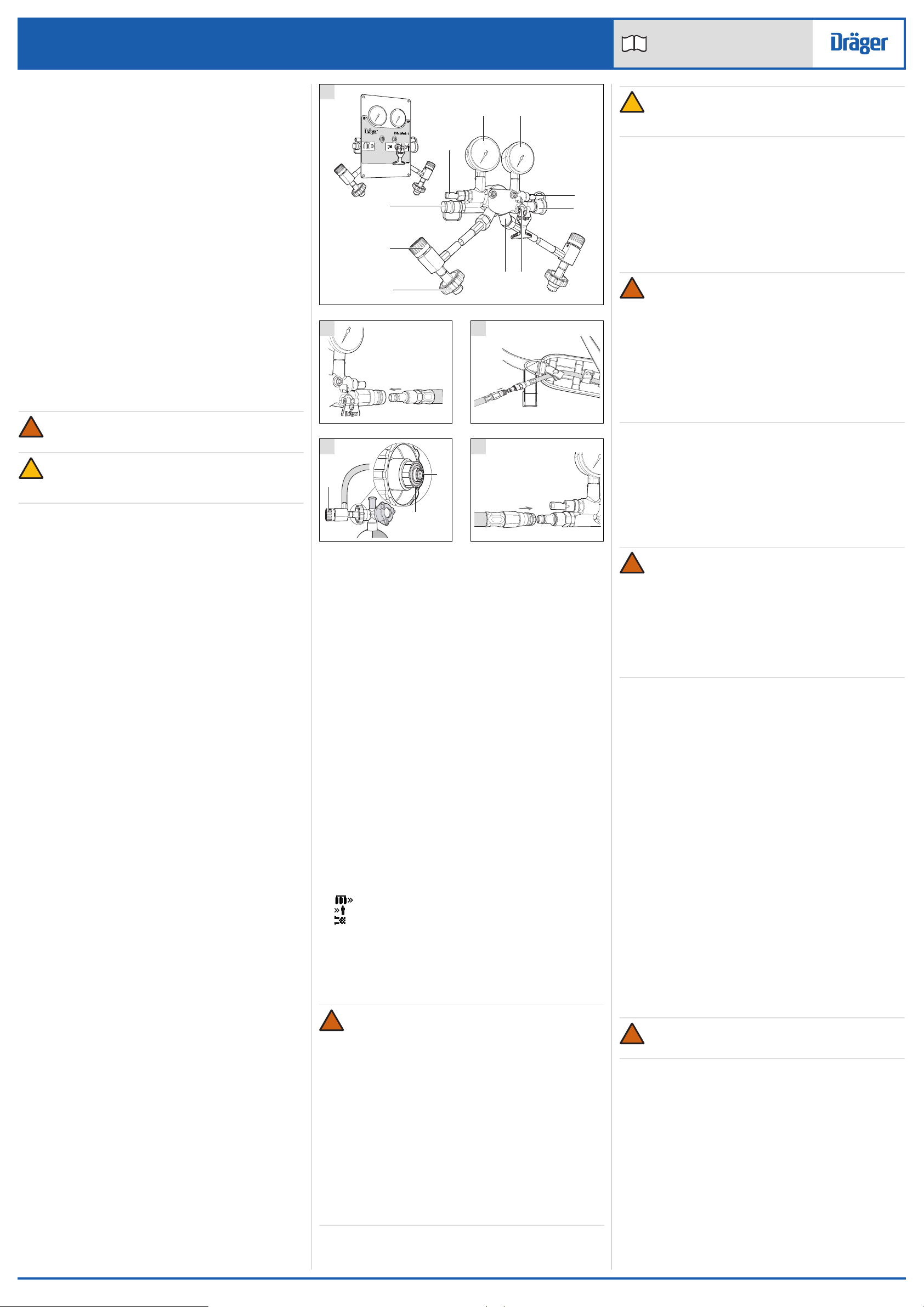
Referring to Fig 1, the features and components of the Pneumatic
Assembly are:
●The high-pressure input connectors (7) are standard cylinder-type
threaded connectors.
●The medium-pressure input connector (9) is a male quick connector
which has an internal non-return valve.
●The output connector (4) is a female quick connector, which has a
valve that self-seals when disconnected.
●A high-pressure gauge (1) indicates cylinder pressure.
●A medium-pressure gauge (2) indicates output pressure.
●A high-pressure whistle (10) sounds to indicate low cylinder pressure.
●A medium-pressure whistle (3) sounds to indicate low output pressure.
If the Pneumatic Assembly is using an external medium-pressure
supply, the whistle indicates that the external supply pressure is low.
●An internal pressure reducer converts the high-pressure input to a
medium-pressure output.
●A relief valve (5) in the medium-pressure system and bleed valves (8)
on the high-pressure connectors release air from the system when
operated.
The Pneumatic Assembly is available as a one-cylinder or two-cylinder
version. The two-cylinder version allows the user to remove depleted
cylinders and replace them with fully charged cylinders when required.
Repeatedly replacing alternate depleted cylinders can provide an
uninterrupted air supply to the attached breathing apparatus wearers.
Internal non-return valves (Fig 1, Item 6) ensure that air from the other
cylinder can not escape when a depleted cylinder is removed.
Holes in the corners of the front plate can be used to secure the Pneumatic
Assembly. The holes are: approximately 6.2 mm diameter; and
approximately 155 x 210 mm between centres.
2.2 Intended use
The Pneumatic Assembly is used with breathing air cylinders and an
external breathing air supply (works airline or compressor) to provide a
medium-pressure output. When used with approved Dräger airline
equipment, it supplies breathing air to one or two breathing apparatus
wearers.
It is intended to be used with only the air cylinder(s) connected (self-
contained use), or with the air cylinder(s) and an external medium-
pressure supply connected (external-supply use). When it is used with an
external supply the cylinders provide a backup air supply.
The breathing apparatus, cylinders and other accessories used with this
product must be certified Dräger components assembled in an approved
configuration. See Section 10 for the compatible airline equipment and
configurations. Contact Dräger for further information.
2.3 Approvals
The European standards, guidelines, and directives according to which
this product is approved are specified in the declaration of conformity (see
declaration of conformity or www.draeger.com/product-certificates).
2.4 Use in potentially explosive atmospheres
●The PAS AirPack Series is type tested as suitable for use in potentially
explosive atmospheres. The combinations are suitable for use in
hazardous areas of Zone 1 and 2 for explosion group IIA and IIB and for
Zone 21 and 22.
!
!
2.4.1 Special conditions for safe use
The Airline Systems shall not be used in the vicinity of processes where
high charges are generated if explosive atmospheres are present (for
example, where rapid filling processes are carried out – big bag filling – or
many actions of fast limit surface separation are done). In such cases,
hazardously high charges of the Airline Systems may occur due to
electrostatic induction.
The breathing apparatus and the compressed air cylinders which are used in
combination with the Airline Systems each have to meet the applicable
requirements of the equipment categories and explosion groups relevant to
the respective Airline System.
The Airline Systems have to be moved manually inside explosive
atmospheres by the user (pushing or pulling). It is mandatory to use floors
in Zone 1 and Zone 21 that are able to discharge electricity where dusts of
minimum ignition energies < 10 mJ are present.
If air supply hoses are used with a total length > 50 m, then the couplings which
are connected to the hoses in a conductive manner have to be provided with
an additional earth contact (after a hose length of 50 m) and integrated into the
operating eqipotential bonding.
●Do not charge the cylinder in a potentially explosive atmosphere.
2.5 Explanation of marking and symbols
Refer to the relevant authority for explanation of approval body symbols
and markings. Examples of other marking on the product:
BRBA-1359 – Dräger serial number
08/09 – Month and year of manufacture
3353261 – Dräger part number
HP – High pressure
MP – Medium pressure
– Medium-pressure input
– Medium-pressure output
– Relief valve
Where appropriate, the marking “F” on the apparatus and CAST
(compressed-air supply tube) indicates that both can be used where
flammability may be a risk. Marking on the compressed-air supply tube
indicates that the tube is heat resistant (H) and/or antistatic (S).
3 Use
WARNING
The cylinder and airline air quality shall meet the requirements for
breathing air according to EN 12021. Do not use oxygen or
oxygen-enriched air. The moisture content of breathing air should
be controlled within the EN 12021 limits to avoid freezing the
apparatus.
Carry out a risk assessment of the workplace to ensure that it is
not possible to connect to any airline supply other than breathable
air (e.g. Nitrox).
Before using airline equipment, ensure that the air supply meets
the air quality requirements, and complies with the airline
pressure, flow and hose requirements (see Section 8 and Section
10), and has been issued with a permit for use if necessary.
Position the Pneumatic Assembly in a safe and uncontaminated
area, and ensure that it is securely held or placed in a position
where it cannot be damaged.
Dräger recommend that the user carries out a risk assessment to
establish local procedures to be followed in the event of failure of
the air supply.
!
CAUTION
Impact damage to the Pneumatic Assembly may prevent cylinder
valve connection or cause an air leak. Handle the equipment with
care.
When remote wearers are connected to the Pneumatic Assembly, a
controller must be appointed to monitor the gauges and whistles of the
product throughout the operation. The controller must maintain the air
supply to the wearers and must ensure that any precautionary or
emergency signals are conveyed to the remote wearers in line with local
procedures and these Instructions for Use.
3.1 Preparation for use
1. Carry out a visual inspection (see Section 3.4.1).
2. Connect the air cylinder or cylinders (see Section 3.4.2).
3. Carry out a full functional test (see Section 3.4.5).
WARNING
Incorrect airline equipment configurations may result in insufficient
air flow to breathing apparatus wearers or increase the possibility
of air supply failure. See Section 10 for the compatible airline
equipment and configurations.
Prepare the breathing apparatus for use (see the Instructions for
Use supplied with the breathing apparatus). Observe the safety
information and carry out all preparation and functional testing
tasks before use.
Do not use the Pneumatic Assembly to supply air to more than two
breathing apparatus wearers at any time. If a controller is
appointed, and is required to wear breathing apparatus and to
connect to the equipment then only one other user is permitted.
4. Connect the airline equipment (extension hoses, Y-piece, etc.) to the
medium-pressure output connector (Fig 2).
5. Depending on the required use, do one of the following:
○Self-contained use – Fully open the cylinder valve (open only one
cylinder valve on a two cylinder version).
○External-supply use – Connect the external supply (see
Section 3.4.4). Ensure that cylinder valves are fully closed.
6. Put on the breathing apparatus and connect to the airline equipment
(Fig 3 shows a typical breathing apparatus connector).
3.2 During use
WARNING
An appointed controller or the breathing apparatus wearers must
monitor the Pneumatic Assembly gauges and whistles during use.
Procedures to warn and evacuate remote users must be in place.
The effective working duration of the equipment is dependent on
the initial air supply available and the breathing rate of the wearers.
Do not commence any operation using a cylinder that is less than
80 per cent full.
At very high work rates the pressure in the face mask of a
breathing apparatus wearer may become negative at peak
inhalation flow.
●Breathe normally and proceed to the work area taking care with any
airline equipment.
●On receipt of an evacuation signal, withdraw immediately to a safe
area (see local instructions for full evacuation procedures).
●When the task is complete, withdraw to a safe area before removing
the breathing apparatus.
●The high-pressure and medium-pressure whistles indicate that there is
low pressure in the associated system. If a warning whistle sounds,
carry out the necessary actions depending on the configuration of the
Pneumatic Assembly (see Sections 3.2.1 or 3.2.3).
3.2.1 Medium-pressure whistle sounds during external-supply use
Fully open one cylinder valve, and disconnect the external supply from the
Pneumatic Assembly. Continue the task as a self-contained use task.
3.2.2 Medium-pressure whistle sounds during self-contained use
Breathing apparatus wearers must proceed in line with breathing
apparatus Instructions for Use and local procedures.
3.2.3 High-pressure whistle sounds during self-contained use
●If there is a second/offline fully-charged cylinder connected to the
Pneumatic Assembly, proceed as follows:
a. Fully open the valve of the second/offline cylinder.
b. Close the valve of the empty cylinder and then open its bleed valve.
c. If a replacement cylinder is available, immediately remove the
empty cylinder (see Section 3.4.3) and fit a replacement (fully
charged) cylinder (see Section 3.4.2).
●If the second/offline cylinder is empty, or there is no second/offline
cylinder connected: breathing apparatus wearers must proceed in line
with breathing apparatus Instructions for Use and local procedures.
3.3 After use
WARNING
Do not remove the breathing apparatus until in a safe breathing
environment.
1. Once in a safe area, remove all breathing equipment.
2. Disconnect the external supply from the Pneumatic Assembly and fully
close all cylinder valves.
3. Pull the handle of the relief valve (Fig 1, Item 5) to vent all air from the
system.
4. Disconnect any airline equipment from the Pneumatic Assembly and
fit all protection caps.
5. Disconnect the air cylinders if necessary (see Section 3.4.3).
6. Carry out the after use maintenance tasks in the maintenance table
(see Section 5.1).
3.4 Common user tasks
3.4.1 Visual inspection
Check that the Pneumatic Assembly is clean and undamaged, paying
particular attention to pneumatic components, hoses and connectors.
Typical signs of damage that may affect the operation of the Pneumatic
Assembly include impact damage, abrasion, cutting, corrosion and
discolouration. Report damage to service personnel or Dräger and do not
use the Pneumatic Assembly until faults are rectified.
!
!
!
!
3
4
1
10
6
75
9
2
8
1
3222
3228
2
3248
3
3226
4
2
3
1
3227
5
PAS®AirPack
Pneumatic Assembly Instructions for Use
i
PAS®is a registered trademark of Dräger 3357744 (A3-D-P) Page 2 of 3
3.4.2 Connecting air cylinders
Only connect fully charged cylinders that are approved for use, fully
serviceable and in date. Use 200 bar or 300 bar, steel or composite,
breathing air cylinders with compatible connectors (see Section 8). When
more than one cylinder is used, cylinders must be matched for pressure –
do not mix 200 bar and 300 bar cylinders.
1. Ensure that the air cylinder(s) are securely held.
2. Check the outlet port of the air cylinder, and ensure that the O-ring
(Fig 4, Item 1) and the sintered filter (Fig 4, Item 2) in the input
connector are clean and undamaged.
3. Align the input connector (Fig 1, Item 7) with the cylinder ensuring a
smooth curve of the high-pressure hose. Tighten the hand wheel hand
tight. Do not use tools or over tighten.
4. Close the bleed valve (Fig 4, Item 3) (turn it fully clockwise).
3.4.3 Disconnecting air cylinders
WARNING
High-pressure air release may cause injury to the user or other
personnel near the breathing apparatus. Close the cylinder valve
and fully vent the system before attempting to disconnect an air
cylinder.
1. Close the cylinder valve and then open the bleed valve.
2. Disconnect the high-pressure input connector from the cylinder valve.
3.4.4 Connecting an external supply
CAUTION
The cylinder valves must remain fully closed during external-
supply use. If cylinder valves are open, air from the cylinders will
be used.
A compatible external air supply is a regulated medium-pressure input of
breathing air (see Section 8 and Section 10).
1. Select a suitable air supply and adaptor hose.
2. Check that the supply outlet, adaptor hose, and input connector are
clean and undamaged.
3. Connect the external supply to the medium-pressure input connector
of the Pneumatic Assembly (Fig 5).
4. Check that the pressure indicated on the medium-pressure gauge (Fig
1, Item 2) is 6 bar to 10 bar. If necessary, adjust the pressure-
regulating device of the external supply (the nominal setting is 8 bar).
(If the pressure is below 8 bar, a low whistle or hiss may be heard from
the high-pressure whistle during use. This is normal operation for the
unit, and does not affect the functionality of the product).
3.4.5 Functional testing
WARNING
If the breathing equipment fails to meet any of the standards or
parameters described in the functional tests, or if an immediate
leak is evident, there is a system fault. Report the fault to trained
service personnel or contact Dräger. Do not use the breathing
equipment until the fault condition is rectified.
1. Ensure that the cylinder valves and bleed valves are fully closed.
2. Fully open the cylinder valve (open only one cylinder valve on a two
cylinder version).
3. Check the pressures indicated on the pressure gauges:
○The high-pressure gauge must indicate at least 80% of the cylinder
maximum pressure.
○The medium-pressure gauge must indicate 6 bar to 10 bar.
4. For two-cylinder versions, fully open the bleed valve of the second/
offline cylinder. Ensure that there is no audible leak and then re-close
the bleed valve.
5. Fully close the online cylinder valve.
6. Wait one minute and then observe the high-pressure gauge and
reopen the cylinder valve. The gauge must not show an increase in
pressure of more than 10 bar. If there is any leak, investigate and
repair the leak before use (see Section 4). If necessary, use a soapy
solution to locate the leak.
7. Fully close the online cylinder valve again.
8. Pull the handle of the relief valve (Fig 1, Item 5) to vent the air very
slowly and observe the high-pressure gauge. The high-pressure
whistle must commence in the range 60 bar to 50 bar.
9. Release the handle of the relief valve immediately when the whistle
commences. Allow the whistle to fully vent the high-pressure side of
the reducer.
10. Again pull the handle of the relief valve to vent the air very slowly and
observe the medium-pressure gauge. The medium-pressure whistle
must commence in the range 5 bar to 4 bar.
Continue testing for two-cylinder versions only.
11. Repeat Steps 2 to 7 for the opposite cylinder.
12. Pull the handle of the relief valve to fully vent the system.
4 Troubleshooting
Disconnect or replace any associated equipment and retest before
referring to the troubleshooting table.
Contact service personnel or Dräger when the remedy information
indicates a service task, or if the symptom remains after all remedy actions
have been attempted.
Symptom Fault Remedy
High-pressure or
medium-pressure air
leak
Loose/damaged
connector or faulty seal
Reconnect or tighten
connectors and retest.
Pressure reducer or
hose leak
Service task
High or low medium-
pressure
Pressure reducer out of
specification
Service task
Poor sounding
whistle
Dirt Clean and retest
Whistle not
functioning correctly
Defective activation
mechanism
Service task
!
!
!
5 Maintenance
5.1 Maintenance table
Service and test the PAS AirPack Pneumatic Assembly, including out-of-
use equipment, in accordance with this table. Record all servicing and
testing details in the equipment log book. See also the maintenance
information for any associated breathing equipment.
Additional inspection and testing may be required in the country of use to
ensure compliance with national regulations.
Notes
Dräger Recommendations
1. Clean the equipment if it is dirty. If it the equipment has been exposed
to contaminants, disinfect any components that come into direct and
prolonged contact with the skin.
2. These maintenance tasks may only be carried out by Dräger or trained
service personnel. Details of the tests are contained in the technical
manual which is issued to service personnel that have attended a relevant
Dräger maintenance course.
5.2 Air cylinder charging
WARNING
Air quality for compressed-air cylinders must conform to
requirements of EN 12021.
●Refer also to the instructions supplied with the cylinder and the
charging unit for recharging the cylinder.
●Only charge compressed-air cylinders which:
○Conform to national standards.
○Feature the original manufacturer’s test date and test mark.
○Have not exceeded the test date indicated on the cylinder by the
last testing station.
○Are not damaged.
●To prevent ingress of moisture into the cylinder, ensure that the
cylinder valve remains closed until connected to the charging unit.
●Recharge to the rated working pressure of the cylinder. Dräger
recommend a charge rate of 27 bar/minute (rapid charging will
increase the temperature resulting in an incomplete charge).
●To prevent overcharging of the cylinder, Dräger recommend using a
pressure-limiting device on the charging compressor.
5.3 Cleaning and disinfecting
CAUTION
Do not immerse the PAS AirPack Pneumatic Assembly in water or
cleaning solutions and do not place the PAS AirPack Pneumatic
Assembly in a heated drying facility.
For information about suitable cleaning and disinfecting agents
and their specifications refer to document 9100081 on
www.draeger.com/IFU.
Refer also to the Instructions for Use for the lung demand valve, face mask
and other associated equipment.
●Use only clean lint-free cloths
1. Clean the PAS Airpack Pneumatic Assembly manually using a cloth
moistened with cleaning solution to remove excess dirt.
2. Apply disinfecting solution to all internal and external surfaces.
3. Rinse all components thoroughly with clean water to remove all
cleaning and disinfecting agents.
4. Dry all components using a dry cloth, or in air.
5. Contact service personnel or Dräger if disassembly of pneumatic or
electronic components is required.
6 Storage
Store the equipment between -15 °C and +25 °C. Ensure that the
environment is dry, free from dust and dirt, and does not subject the
equipment to wear or damage due to abrasion. Do not store the equipment
in direct sunlight.
7 Disposal
When required, dispose of the Pneumatic Assembly in line with local or
national regulations for waste disposal.
Component/
System
Task After
use
Every
month
Every
year
Every
six
years
Complete
equipment
Visual inspection (see
Note 1 and
Section 3.4.1)

Functional test (see
Section 3.4.5)

High-
pressure
input
connectors
Renew the O-ring and
sintered filter (see
Note 2)

Pressure
reducer
Overhaul. Contact
Dräger for the Repair
Exchange (REX)
service

Cylinder Charge to correct
pressure (see
Section 5.2)

Check the initial test
date stamped on the
cylinder

Cylinder pressure test
and recertification
Carry out in line with national
regulations
Cylinder
valve
Basic overhaul During cylinder pressure test or
on condition
!
!
8 Technical data
Operating conditions
●Temperature: -30 to +60 °C.
●Usage area: suitable for indoor and outdoor use.
High pressure
●Input connector: 200 bar or 300 bar, standard G5/8” connector as per
EN 144-2.
●Input: 200 bar or 300 bar breathing air cylinder.
Medium pressure
●Input and output connectors: Dräger quick connectors (compatible
with CEJN 344 and Rectus 95KS series).
●Input and output: 6 bar to 10 bar (8 bar nominal) breathing air at a flow
rate of >600 litres/min. Important note: do not exceed 10 bar.
Whistle operation
●High-pressure whistle commences in the range: 60 bar to 50 bar.
●Medium-pressure whistle commences in the range: 5 bar to 4 bar.
●Whistles cease in the range: 1.75 bar to 0 bar.
●Whistle volume: >90 dBA.
9 Compatible airline equipment and
configurations
9.1 Airline equipment configurations
WARNING
Airline equipment must allow the input pressure and flow specified
in the breathing apparatus instructions to be met. Incorrect
configurations may result in insufficient air flow to breathing
apparatus wearers or increase the possibility of air supply failure.
9.1.1 Dräger airline equipment and breathing apparatus
No more than five connections are permitted per line on the output side of
the PAS AirPack Pneumatic Assembly (a Y-piece is treated as two
connections). Additionally, the maximum combined length of the extension
hoses is 100 m. The figures below (not to scale) show some examples of
the maximum number of connections (C1 to C5) and maximum hose
lengths that are permissible in an output configuration using Dräger
equipment.
One breathing apparatus wearer
Breathing air supply equipment
External medium-pressure supply
(see Section 8 for the specification
and connector type)
High-pressure supply (see Section 8
for the specification and connector
type)
Dräger supply, control and monitoring equipment
Dräger PAS AirPack Pneumatic
Assembly (two-cylinder version)
Dräger PAS AirPack Pneumatic
Assembly (one-cylinder version)
Airline equipment (approved to the relevant EN standard)
Extension hose (lengths ranging
from 3 m to 50 m available from
Dräger)
Y-piece
Hose reel (Dräger hose reel has
50 m of hose)
Airline filter unit
In-line medium-pressure whistle
Breathing apparatus
Airline set (EN 14593-1)
Escape/airline set with automatic
switch-over valve (ASV) and airline
connector (EN 402/EN 14593-1)
Working set with automatic switch-
over valve (ASV) and airline
connector (EN 137/EN 14593-1)
'
!
45 m
C1 C2 C3 C4 C5
45 m 5 m 5 m
3240
PAS®AirPack
Pneumatic Assembly Instructions for Use
i
PAS®is a registered trademark of Dräger 3357744 (A3-D-P) Page 3 of 3
3357744
© Dräger Safety UK Limited
Edition 08 – October 2018 (Edition 01 – February 2010)
Subject to alteration
Draeger Safety UK Limited
Ullswater Close Tel +44 1670 352 891
Blyth, NE24 4RG Fax +44 1670 356 266
United Kingdom www.draeger.com
Two breathing apparatus wearers
Two breathing apparatus wearers (with stand-alone hose reel)
9.1.2 Medium-pressure Input
The medium-pressure input is from a factory airline or compressor using
a suitable extension hose, and filter unit if required. Any airline equipment
that is used in the input line must allow the medium-pressure input
requirement to be met (see Section 8).
Input with extension hose
Input with Dräger airline filter unit
30 m
C1 C2
30 m
C3
20 m
C4
C5
C5
C4
20 m
3242
30 m 50 m
(HOSE REEL)
10 m
10 m
C1 C2 C3
C4
C4
C5
C5
3241
3244
'
3243

Other Dräger Safety Equipment manuals

Dräger saver PP Series User manual

Dräger

Dräger saver PP Series User manual

Dräger PAS ASV User manual

Dräger

Dräger PAS ASV User manual

Dräger CDR 4500 User manual

Dräger

Dräger CDR 4500 User manual

Dräger UCF 6000 User manual

Dräger

Dräger UCF 6000 User manual

Dräger SPC 4900 User manual

Dräger

Dräger SPC 4900 User manual

Dräger BG ProAir User manual

Dräger

Dräger BG ProAir User manual

Dräger FPS 7000 RP User manual

Dräger

Dräger FPS 7000 RP User manual

Dräger X-plore 4340 EN 140 User manual

Dräger

Dräger X-plore 4340 EN 140 User manual

Dräger PSS 4000 Series User manual

Dräger

Dräger PSS 4000 Series User manual

Dräger CPS 5900 User manual

Dräger

Dräger CPS 5900 User manual

Dräger PSS 7000 Series User manual

Dräger

Dräger PSS 7000 Series User manual

Dräger Panorama Nova PE Series User manual

Dräger

Dräger Panorama Nova PE Series User manual

Dräger CPS 5800 User manual

Dräger

Dräger CPS 5800 User manual

Dräger SPC 4800 User manual

Dräger

Dräger SPC 4800 User manual

Dräger FPS 7000 HUD User manual

Dräger

Dräger FPS 7000 HUD User manual

Dräger Oxy 3000 MK III Trainer User manual

Dräger

Dräger Oxy 3000 MK III Trainer User manual

Dräger saver CF Series User manual

Dräger

Dräger saver CF Series User manual

Dräger X-plore 2100 User manual

Dräger

Dräger X-plore 2100 User manual

Dräger Oxyboks KT User manual

Dräger

Dräger Oxyboks KT User manual

Dräger SPC 4700 User manual

Dräger

Dräger SPC 4700 User manual

Dräger Saver PP Series User manual

Dräger

Dräger Saver PP Series User manual

Dräger X-plore 8000 User manual

Dräger

Dräger X-plore 8000 User manual

Dräger X-plore 6000 User manual

Dräger

Dräger X-plore 6000 User manual

Dräger X-plore 8000 User manual

Dräger

Dräger X-plore 8000 User manual

Popular Safety Equipment manuals by other brands

Biobase BSC-4FA2 user manual

Biobase

Biobase BSC-4FA2 user manual

FAAC MSE 110 W manual

FAAC

FAAC MSE 110 W manual

Kong FORZA manual

Kong

Kong FORZA manual

Essilor INFIELD Terminator instruction manual

Essilor

Essilor INFIELD Terminator instruction manual

Emerson GEO10 Reference manual

Emerson

Emerson GEO10 Reference manual

CAMP Andry manual

CAMP

CAMP Andry manual

VALTIR QuadGuard M10 product manual

VALTIR

VALTIR QuadGuard M10 product manual

EUCHNER ESM-ES3 Series operating instructions

EUCHNER

EUCHNER ESM-ES3 Series operating instructions

SWITLIK FACE SHIELD Cleaning and Care Instructions

SWITLIK

SWITLIK FACE SHIELD Cleaning and Care Instructions

A.HABERKORN UNI-2 FI INSTRUCTIONS FOR USE AND TEST MANUAL

A.HABERKORN

A.HABERKORN UNI-2 FI INSTRUCTIONS FOR USE AND TEST MANUAL

Eller BA 300 instruction manual

Eller

Eller BA 300 instruction manual

Nielsen ShoulderDolly ProLift HD3500 instruction manual

Nielsen

Nielsen ShoulderDolly ProLift HD3500 instruction manual

Checkmate ecoAnch2or user manual

Checkmate

Checkmate ecoAnch2or user manual

Top Lock 71015 quick start guide

Top Lock

Top Lock 71015 quick start guide

Eaton CEAG GuideLed 10011 LED CG-S Mounting and operating instructions

Eaton

Eaton CEAG GuideLed 10011 LED CG-S Mounting and operating instructions

Crewsaver CREWFIT 150N Service manual

Crewsaver

Crewsaver CREWFIT 150N Service manual

Lunasea LunaSafe LL63 instructions

Lunasea

Lunasea LunaSafe LL63 instructions

RIB F97I Guide

RIB

RIB F97I Guide

manuals.online logo
manuals.online logoBrands
  • About & Mission
  • Contact us
  • Privacy Policy
  • Terms and Conditions

Copyright 2025 Manuals.Online. All Rights Reserved.