Metek MRR-2 User manual

10.2010 Valid for MRR Service Version ≥5.2.0.9
MRR-2
Micro Rain RADAR
User Manual

10.2010 Valid for MRR Service Version ≥5.2.0.9
METEK
Meteorologische MesstechnikGmbH
Fritz-Strassmann-Strasse4
D-25337 Elmshorn
Germany
Fon +49 4121 4359-0
Fax +49 4121 4359-20
e-mail info@metek.de
internet http://www.metek.de
Copyright: © 2010 METEK GmbH
All Rights reserved. No part of this manual may be reproduced, transmitted,
stored in a retrieval system, nor translated into any human or computer lan-
guage, in any form or by any means, electronic, mechanical, optical, chemical,
manual, or otherwise, without the prior written permission of the copyright
owner.

METEK Micro Rain Radar MRR-2 1
10.2010 Valid for MRR Service Version ≥5.2.0.9
Table of Contents
1Safety Precautions............................................................................... 3
2How to use this manual....................................................................... 5
3Measuring Principle............................................................................. 6
4System Description.............................................................................. 7
4.1 Overview................................................................................................ 7
4.2 Description of the Components............................................................ 10
4.2.1 Parabolic Dish................................................................................... 10
4.2.2 Antenna Heating (Option) ................................................................. 10
4.2.3 RADAR Control and Processing Device and Transceiver................. 10
4.2.4 Junction Box / Power Supply ............................................................ 11
4.2.5 Cable RCPD-Junction Box................................................................ 13
4.2.6 Cable Junction Box-PC..................................................................... 13
4.2.7 Control- and Evaluation Computer (PC)............................................ 14
5Hardware Installation......................................................................... 15
5.1 General Provisions............................................................................... 15
5.2 Site Conditions..................................................................................... 15
5.3 Installation Procedure .......................................................................... 16
6Control Program................................................................................. 18
6.1 Installation............................................................................................ 18
6.2 Using the Control Program................................................................... 18
6.2.1 Main Menu ........................................................................................ 21
6.2.2 Control Commands Menu................................................................. 22
6.2.3 Output Parameters Menu..................................................................22
6.2.4 Device Parameters Menu.................................................................. 25
6.2.5 Parameter Storage............................................................................ 27
6.2.6 Status messages and time-axis control............................................. 29
6.3 Instantaneous and averaged data........................................................ 31
6.3.1 Format description ............................................................................ 31
6.3.2 Example............................................................................................ 36
6.4 Raw data.............................................................................................. 39
6.4.1 Format Description............................................................................39

METEK Micro Rain Radar MRR-2 2
10.2010 Valid for MRR Service Version ≥5.2.0.9
6.4.2 Example ............................................................................................40
6.5 Removing of the Software....................................................................41
7Detailed description of the MRR-2 control program........................41
7.1 Communication-, Data-, and Error-Service (CDES) .............................42
7.1.1 Communication Service.....................................................................42
7.1.2 Data Recording .................................................................................42
7.1.3 Error Protocol ....................................................................................43
7.2 Control Program User Interface (CPUI)................................................44
8MRR-2 Specifications.........................................................................47

METEK Micro Rain Radar MRR-2 3
10.2010 Valid for MRR Service Version ≥5.2.0.9
1Safety Precautions
To operate the MRR-2 a mains voltage of 210-240 VAC is needed for the
power supply. An improper handling can be dangerous to you. Only
competent and instructed persons should work with this system or with
parts of it.
The outdoor installation must not be performed in case of an approach-
ing thunderstorm, to avoid a possibly endangering of personnel by
lightning.
There are not known any health hazards originating from the emitted
electromagnetic radiation of about 50 mW. Nevertheless you should
take care that everybody keeps out of the beam above the antenna
(parabolic dish) when it is in operation.
All connecting cables, plugs, and couplings of the MRR-2 are not inter-
changeable to prevent any erroneous assembly. This safety precaution
is disabled if other types of plugs are installed by the user. Therefore
any guarantee explicitly expires and METEK accepts no responsibility
for injuries to persons, damage of equipment or other consequences
connected with not authorized changing of connectors, cables or other
parts of the system.
Depending on regional rules for the use of electromagnetic transmitters
frequency permission might be necessary. The operator of the system
will be liable for the achievement of such permission. However METEK
will be of help with providing adequate information. Copies of the certi-
fications for Germany can be found in chapter 6 of this manual.


METEK Micro Rain Radar MRR-2 5
10.2010 Valid for MRR Service Version ≥5.2.0.9
2How to use this manual
The delivered hardware items are described in section 4. Make sure that the
delivery is complete and free of damage. Consult section 5 for setting up the
hardware. In section 6 the installation and use of the control software is de-
scribed. The technical specifications are listed in section 8.
Section 7 contains more detailed information which is not needed for standard
operation.
All auxiliary information marked by a grey vertical line on the left margin may
be skipped at first reading as it is not needed for standard setting up and op-
eration.

METEK Micro Rain Radar MRR-2 6
10.2010 Valid for MRR Service Version ≥5.2.0.9
3Measuring Principle
The Micro Rain Radar MRR-2 retrieves quantitative rain rates, drop size dis-
tributions, radar reflectivity, fall velocity of hydro meteors and other rain pa-
rameters simultaneously on vertical profiles up to several kilometers above
the radar.
It operates with electromagnetic radiation at a frequency of 24,230 GHz with
a modulation of 0.5 15 MHz according to the height resolution (e.g. 300 m
10 m). The radiation is transmitted vertically into the atmosphere where a
small portion is scattered back to the antenna from rain drops or other forms
of precipitation.
Due to the falling velocity of the rain drops antenna there is a frequency devi-
ation between the transmitted and the received signal (Doppler frequency).
This frequency is a measure for the falling velocity of the rain drops. Since
drops with different diameters have different falling velocities the backscat-
tered signal consists of a distribution of different Doppler frequencies. The
spectral analysis of the received signal yields a power spectrum which is
spread over a range of frequencies lines corresponding to the Doppler fre-
quencies of the signal.
The RCPD determines this power spectrum with a high time resolution (25
per second) and sends mean power spectra every 10 s to the connected
control and data acquisition system, where the reflectivity spectrum is calcu-
lated considering the calibration parameters of the RADAR module. Using
known relations between fall velocity, rain drop size and scattering cross sec-
tion the drop spectrum (or drop size distribution) is derived. The integration
over the entire drop size distribution, considering further correction terms,
followed by further averaging over 10 to 3600 seconds, results in rain rate
and liquid water content.
The output signal of the RADAR is transmitted continuously (CW mode), a
linearly decreasing saw tooth modulation of the transmit signal (FM mode)
makes it possible to perform profile measurements with selectable range
resolution.
The RADAR antenna is an offset parabolic dish with vertical beam orienta-
tion. This antenna design allows rainwater to drain without building ponds. In
order to avoid disturbances from snow, which could cover the antenna dish,
optional antenna heating is offered.

METEK Micro Rain Radar MRR-2 7
10.2010 Valid for MRR Service Version ≥5.2.0.9
4System Description
4.1 Overview

METEK Micro Rain Radar MRR-2 8
10.2010 Valid for MRR Service Version ≥5.2.0.9
Figure 1:
Components of the
System
1. Parabolic Dish,
2. Transceiver,
3. RCPD,
4. Junction Box,
5. Cable Junction Box-PC,
6. AC Power Cable,
7. Cable RCPD-
Junction Box,
8. Antenna Arm,
9. Pivot,
10. Tube Socket
1
4
5
6
2
Case can vary in style
3
7

METEK Micro Rain Radar MRR-2 9
10.2010 Valid for MRR Service Version ≥5.2.0.9
The Control- and Evaluation Computer, a commercial PC, (not part of delivery)
must be ordered separately. The operating system must be Windows® 2000
or XP. (Windows® Vista and Windows 7 is not supported).

METEK Micro Rain Radar MRR-2 10
10.2010 Valid for MRR Service Version ≥5.2.0.9
4.2 Description of the Components
4.2.1 Parabolic Dish
The antenna is used for the transmission of the RADAR signals and the re-
ceiving of backscattered signals. It is designed as an offset parabolic dish (1).
Its largest diameter is 70 cm, the beam width is 2°. Due to the offset-design of
the parabolic dish rainwater can drain off.
For antenna mounting the tube socket (10) (inner Ø = 49.4 mm, out-
er Ø = 54.4 mm) is to be plugged onto a pole with an outer diameter of max.
49 mm. The socket is fastened with an M10 screw (10 mm Ø).
Connect a ground wire to this screw which serves as a surge protector.
The pivot (9) is factory-adjusted, so that vertical orientation of the mounting
tube socket results in a vertical orientation of the antenna beam. (Ignore the
scale on the pivot).
The parabolic dish must not be moved in its pivot (9), because this would
cause beam deviations from vertical and would result in erroneous
measurements.
The transmitting and receiving properties of the antenna affect the radar cali-
bration. Therefore the reflector surface should be clean (e.g. free from leaves
or wet snow). For the same reason any mechanical deformation of the para-
bolic dish must be avoided. If nevertheless obvious deformation occurred, the
reflector must be replaced.
4.2.2 Antenna Heating (Option)
+
Figure 2: Antenna Heating
The back side of the reflector is optionally equipped with a heating coil. It is
covered and sealed with a molded lid (11) which provides also extra stability
for the reflector. The energy consumption increases with decreasing tempera-
tures and amounts to maximum 500 W. The heating is activated when the
temperature falls below a threshold which can be adjusted in the heating-
junction box (13). The heating coil works with 230 VAC voltage supply and
needs an extra power cable which is connected to (1).
4.2.3 RADAR Control and Processing Device and Transceiver

METEK Micro Rain Radar MRR-2 11
10.2010 Valid for MRR Service Version ≥5.2.0.9
Figure 3: RCPD and Transceiver
The RCPD (3) gener-
ates the RADAR
transmit modulation
signal and passes it
to the transceiver (2)
through cable (15). It
analyses the
backscattered receiv-
er signal, calculates
Doppler spectra and
transfers average
power spectra (re-
a-
to the control and
evaluation PC, where
these spectra are in-
terpreted. The RCPD
is located in a water
protected IP65 hous-
ing, which is fixed to
the antenna arm (8).
At the bottom side of
the RCPD is the
socket (14) for cable
(7). The electronic
components inside
need any service. As
far as possible the
RCPD should not be
opened by the user.
4.2.4 Junction Box / Power Supply

METEK Micro Rain Radar MRR-2 12
10.2010 Valid for MRR Service Version ≥5.2.0.9
Figure 4: Junction Box Left:Front Side, Right: Back Side
The junction box is used to pass through the communication between the PC
and the RCPD. For this purpose it has a 25-pin D-sub-miniature socket, (16)
for the data cable (5) to the PC and a flanged socket (17) for the cable (7) to
the RADAR RCPD (3).
The power supply for the RCPD and Transceiver is also integrated in the junc-
tion box. An IEC connector for the mains supply of 230 VAC (17) is on the
front side of the case. On the back side are two sockets for banana plugs for
the connection of an alternative external DC power supply (19). The power
supply (24 VDC) for the RCPD and Transceiver is also passed through cable
(7).
Note : The junction box is not appropriate for outdoor operation.
METEK Micro Rain Radar MRR-2 13
10.2010 Valid for MRR Service Version ≥5.2.0.9
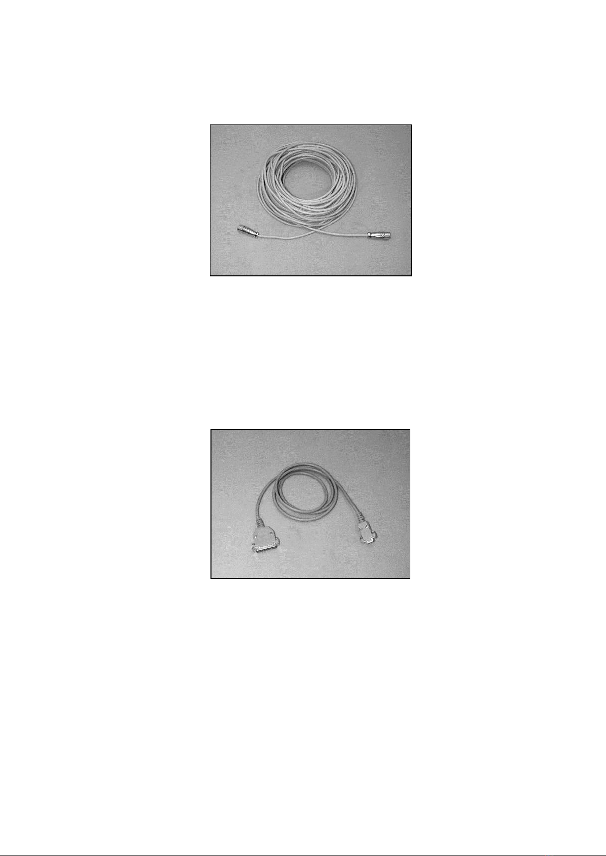
4.2.5 Cable RCPD-Junction Box
Figure 5: Cable between Junction Box and RCPD
The cable has a length of 25 m, on both ends are screwed plugs (male and
female respectively). They must be screwed onto the matching plugs at the
junction box (cable has pins) and at the RCPD (cable has sockets).
4.2.6 Cable Junction Box-PC
Figure 6: Cable Junction Box-PC
Data cable with a 9-pin (female) and a 25-pin (male) plug and a length of
1.5 m is delivered. This cable is not appropriate for outdoor applications.

METEK Micro Rain Radar MRR-2 14
10.2010 Valid for MRR Service Version ≥5.2.0.9
4.2.7 Control- and Evaluation Computer (PC)
A personal computer (PC) with the operating system Windows® 2000 or XP
serves for setting the operation parameters and data evaluation of the MRR.
(Windows® Vista and Windows® 7 are not supported).
The PC must have at least one serial port which will be configured by the con-
trol program as follows:
57600 baud,
8 data bits, no parity,
software protocol (XON/XOFF), no hardware protocol (handshake).
Pinning (D-Sub-25-socket at the device) :
Pin 2 RD received data to the device
Pin 3 TD transmitted data from the device
Pin 7 GND ground
The control program which is needed to operate the MRR-2 is part of delivery.
Its installation and operation is described in section 6 Control Program page 18.

METEK Micro Rain Radar MRR-2 15
10.2010 Valid for MRR Service Version ≥5.2.0.9
5Hardware Installation
5.1 General Provisions
Before you start the system, all cable connections must be set up.
Only the antenna unit including RCPD, Transceiver and cable (7) are
designed for outdoor operation. All other components, e.g. the junction
box and PC, must be installed in a weather protected environment with
temperatures within 5 - 50 °C.
The electronic cases may be opened only in dry environment. Especial-
ly in outdoor area you risk damage by moisture.
If cables are laid on free field, a cable conduit is recommended.
All cable connections should be protected by strain-reliefs.
Use only the original connectors. Guarantee is void, if other connectors
are installed.
5.2 Site Conditions
Before actual installation the site must be checked for its suitability for rain
measurements.
There must be free view of at least 10° zenith angle over the radar.
Nearby transmitters (base stations of mobile phones, broadcast towers, ra-
dars) can cause interference although they operate nominally at different fre-
quency bands. If such neighborhood is necessary, a simple metallic screen or
larger object (container) obscuring the direct line of sight to the interfering
source can help.
The vicinity of electric machines (e.g. drive of elevators) should be avoided,
since they can create interfering signals which are difficult to screen.
If measurements at very low heights are planned, (with appropriate settings
the MRR-2 allows measurements from a minimum height of 20 m above
ground) take care that the wind field in this level is not disturbed by nearby
buildings, trees, masts etc., because strong turbulence could falsify the data.
In contrast with in-situ rain sensors the exposure of the antenna to the free
wind field is not detrimental but favorable.
Figure 7 shows various examples of MRR installations: On ground, on top of
containers and on top of buildings.
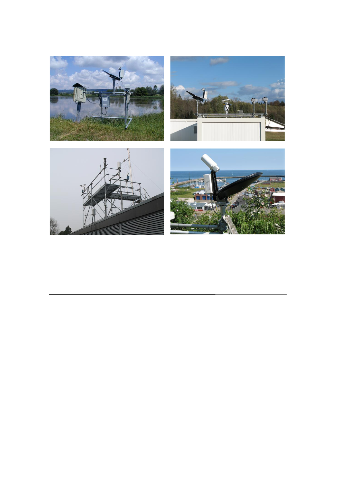
METEK Micro Rain Radar MRR-2 16
10.2010 Valid for MRR Service Version ≥5.2.0.9
Figure 7: Examples of MRR installations
5.3 Installation Procedure
Preparations:
A fixed vertical pole (Ø max. 49 mm, length min. 30 cm) is required for attach-
ing the antenna. Operating of the MRR-2 requires a 230 VAC mains supply,
with a fuse protection of 8 A (slow) minimum. To prevent disturbance of the
device by variations or breaks of the power supply we recommend the use of a
no-break power supply (UPS).
Required Tools: A wrench with 17 mm opening.

METEK Micro Rain Radar MRR-2 17
10.2010 Valid for MRR Service Version ≥5.2.0.9
Installation Steps:
1. Install the control and evaluation computer (PC) according to the docu-
ments of the manufacturer.
2. Plug the tube socket (10) of the RADAR antenna over the attachment
pole and clamp it with the M10 fixing bolt.
3. Check the vertical alignment of the antenna with the built in bubble level
(see Figure 8)
Figure 8: Vertical alignment of the radar beam
4. Attach a ground wire to the fixing bolt for lightning protection.
5. Connect cable (7) between RCPD and Junction Box after mounting of the
antenna.
6. Connect cable (5) to that serial interface of the computer, which was se-
lected in the operating system for the connection of the MRR-2. If this se-
rial port is unknown, it can be looked up in the administration of the "ser-
vices" in the operating system of the computer and it can be changed ac-
cordingly there. See also installation of the control program page 18 ff.
7. Connect cable (6) of the Junction Box to the mains voltage of 230 VAC
(cable (6)).
8. MRR-2 Con-
and the RCPD-firmware.
9. Check the correct data transmission and recording.
Ground wire

METEK Micro Rain Radar MRR-2 18
10.2010 Valid for MRR Service Version ≥5.2.0.9
6Control Program
If the PC for controlling the MRR-2 with was not ordered separately the
programs for controlling the MRR-2 and for data recording are delivered on a
CD-ROM and must be installed on a PC with operating system
Windows® 2000 or Windows® XP. (Older Windows® versions,
Windows® Vista, or Windows® 7 are not supported.)
If the PC was configured and delivered by METEK (optional) 6.1 Installation
may be skipped.
6.1 Installation
For installing the Control Program:
Insert the CD-ROM.
Login as administrator.
Open the program group my computer (icon on the desktop).
Open the folder for the CD-ROM device.
Change to the folder METEK\MrrCtrl.
With the right mouse key click on the file MrrXXXXXX.inf.
Activate the install menu. The files are copied and the registry of the PC
is updated.
When the copy process has finished, reboot the PC.
Note: The data flow rate from the MRR to the PC requires that the PC re-
sponse time does not exceed certain limits. If the PC was configured and de-
livered by METEK (optional), meeting of this request is warranted. Any modern
PC with medium performance is basically sufficient to run the Control Program
without flaws, if there are not too many other tasks running simultaneously.
Particularly virus scanning programs may slow down the PC below the mini-
mum possible value. In that case the data records are corrupted. Check the
integrity of recorded data by visual inspection or by some automated proce-
dure.
6.2 Using the Control Program
After login to the operating system open a command line window and enter the
command MrrCtrl.exe. The following dialogue window appears (The
screenshots in this manual were taken from a Windows® 2000 system.):
Other manuals for MRR-2
1
Table of contents
Other Metek Radar manuals


