Meter-Master 100P User manual

Model 100P
Meter-Master Pressure Recorder
Operating Instructions
Contents
1. Getting Started
1.1 About The Meter-Master Model 100P ...................................... 1
1.2 Meter-Master Care And Maintenance ...................................... 2
1.3 Installing The Model 100 Program Software ............................ 3
1.4 MM100P Specifications............................................................ 4
2. Collecting Data
2.1 Making A Recording................................................................. 6
2.2 Downloading Data And Adding Customer Information ........... 11
3. Graphs And Reports
3.1 Overview: Creating, Printing, Saving, Exporting, Viewing ..... 13
3.2 The Graph Screen.................................................................. 17
3.3 The Report Screen And Exporting ......................................... 21
3.4 Data Grid And Customer Information Screen......................... 23
4. Other Features
4.1 Realtime Display .................................................................... 27
5. Troubleshooting
5.1 List Of Topics ......................................................................... 28
5.2 Field Operation....................................................................... 29
5.3 Computer Operation............................................................... 30
6. Service And Support
6.1 Customer Service................................................................... 33
6.2 Two Year Limited Warranty.................................................... 33
Copyright 2001 F. S. Brainard & Co. All Rights Reserved.
Rev. 1.3 (Feb-06) •Program Software Version 2.08
F. S. Brainard & Company
5 Terri Lane, Unit 15 P.O. Box 366 Burlington, NJ 08016
TEL: 609-387-4300 / 888-388-FLOW (toll free) FAX: 609-387-4304
www.meter-master.com


1.1 GETTING STARTED: About The Meter-Master Model 100P page 1
Chapter One
GETTING STARTED
1.1 About The Meter-Master Model 100P
The METER-MASTER MODEL 100P Pressure Recorder is a battery-powered, portable
pressure recording instrument that offers the same easy-to-use design features as the
Model 100EL flow recorder. A rocker switch toggles the recording on/off and initiates a
test of the sensor pick-up. An LED signal light integral to the rocker switch indicates the
current pressure range by flashing once for every 10 psi of current pressure. Pressure
may be checked at any time without interrupting a recording session. The durable,
ABS/polycarbonate case includes an integral handle that allows the instrument to be
chained for security. The pressure sensor is located inside the recorder case to prevent
damage, and an external hose permits connection to a pipe. Standard hose fittings are
stainless steel, include a quick connect for attaching the hose to the recorder, and a 1/4”
NPT fitting for attachment to the pipe fitting. Optional carbon steel quick connect
fittings offer a relief valve to purge air from the hose once all attachments are secured.
The unit is submersible, easy to set up, and highly accurate.
Twenty different recordings at different locations may be made before downloading.
Memory capacity provides 1.5 days to 3 months of recording time before downloading.
Recording time depends on the size of the data storage interval you select. Recording
automatically stops when the memory is used up; the recorder will not overwrite.
The pressure data is logged into memory for later downloading and analysis on your PC.
The Model 100 Program software functions with all Meter-Master recorders and provides
a variety of report and graph options. Data may also be exported into other widely used
software, such as Lotus, Excel, Quattro Pro, WordPerfect, and MS Word. The
Model 100 Program also offers a real-time 3-D graphic display of the current pressure
level.
Two internal 2 volt, lead-acid, rechargeable batteries power the unit. Because batteries
release small quantities of gas when overcharging occurs, there is a low-pressure relief
valve on the back of the unit which enables the gas to escape. Batteries are recharged by
using the battery charger provided; recharging completely discharged batteries takes at
least 14 hours. Continuous AC operation is available via the battery charger. With
proper care, the batteries should last a minimum of three years.
Before using the Model 100P for the first time, be sure to read the next section, "Meter-
Master Care And Maintenance".
Important
Meter-Master products are durably built for long, accurate service in accordance with
military quality standards. Each unit is manufactured at our factory and shipped ready
for operation.

page 2 1.2 GETTING STARTED: Meter-Master Care And Maintenance
F. S. Brainard & Co. reserves the right to modify its designs at any time in order to
supply the best products possible. All instruments are warranted for two years from
either the date of purchase or the date of manufacture (see Section 6.2). Maintenance
agreements are available following the initial two year warranty period.
1.2 Meter-Master Care And Maintenance
The Model 100P requires a minimum of care and maintenance. However, as a piece of
electronic equipment powered by internal, rechargeable batteries, several points should
be kept in mind.
ÎKeep Batteries Charged. Lead-acid battery life is maximized when the batteries are
maintained in a charged condition as often as possible. Complete discharging of lead-
acid batteries can result in their permanent damage. Although the Meter-Master batteries
should last a minimum of 3 months after being fully charged, whenever possible, connect
the Meter-Master to the battery charger when the Meter-Master is connected to the
computer and always recharge the batteries after each use if time permits. Leave the
Model 100P connected to the charger whenever it is not in the field.
Because the Model 100P is built to power-down when it senses low battery power, the
batteries are protected from complete discharge during normal operation. However, after
a power-down due to low battery power, do not allow the Meter-Master to sit for more
than 7 days without recharging.
The Model 100P uses battery power whether it is recording or not. Do not store the
Meter-Master in a discharged condition unless it is connected to the battery charger.
Store the instrument either fully charged or, preferably, connected to the battery charger.
If not connected to the charger while in storage, remember to recharge the batteries at
least once each month.
A battery charger is furnished with the Meter-Master. It has been selected as optimal for
this application. Other chargers may not provide the same level of battery performance.
ÎKeep Sensor Port Clean. Before connecting hose, make sure no dirt or other debris is
lodged inside pressure connector. Flush out with water if necessary; don’t dig out with
anything sharp or hard. Keep protective cap over connector when not in use.
ÎAvoid Needless Submersions. Although the Meter-Master is sealed to resist water
intrusion, care should be taken to avoid needless submersion. If the unit is chained inside
a pit, ensure that it can float up to the top if the pit fills with water. If water accumulates
inside the unit, it should be returned to the factory for service.
ÎHandle Cables With Care. To ensure long cable life, handle cables carefully and avoid
attempting to insert a cable into the wrong receptacle on the front of the unit. Each
connector has a unique number of pins and two channel guides for proper connector
mating. Each cable should seat easily into the receptacle; never try to push or press a
cable into place. (NOTE: Although the RS232 cable and battery cable have a different
number of pins, the RS232 cable can be mistakenly plugged into the Meter-Master
battery connection. No damage will result.)

1.3 GETTING STARTED: Installing The Model 100 Software page 3
ÎHandle Degraded Batteries With Care. Lead-acid batteries contain sulfuric acid. If
contact is made with the acid, immediately flush the area with water. A good neutralizing
solution for sulfuric acid is household baking soda in water. Dispose of lead-acid
batteries with automotive battery scrap at an EPA registered reclaimer. Under normal
circumstances, battery replacement will be performed at our factory.
1.3 Installing The Model 100 Program Software
IF YOU HAVE AN INFRARED CONNECTION ON YOUR COMPUTER (E.G.,
PALM PILOT OR MS ACCESS SYNC): Any infrared connection must be
disabled when using Meter-Master software.
The Model 100 Program for Windows software is designed to run on Windows 3.1, 3.11,
95, 98, NT, 2000, ME, and XP. As a minimum, your computer should have a Pentium
processor, 16MB RAM, and 100MB free hard disk space. A minimum of 32MB of RAM
is recommended.
While the Meter-Master software has been designed to run on a network, it does not work
in all network environments and is not currently supported by F. S. Brainard & Co. in a
network environment. If you encounter a Meter-Master software problem while
operating on your network, reinstall the Meter-Master program on a stand-alone
computer.
TO INSTALL SOFTWARE
1. Insert the CD into your computer’s CD ROM drive.
If the install program does not start automatically, select RUN from the Windows
Start menu (“File” menu in Windows 3.1) and type “E:\setup” (without quotes) in the
Open text box. (Replace “E” with the drive letter of your CD ROM.)
2. Click OK Or Next To Continue. Follow The Onscreen Commands.
When finished, the setup program will create Meter-Master icons and prompt you to
reboot your computer.
3. Open The Meter-Master Program.
Select the Meter-Master for Windows program group and then double-click on the
MMV31 icon.

page 4 1.4 GETTING STARTED: MM100P Specifications
4. Review Communication Port Settings.
After loading the software, you must tell the Meter-Master program which serial port
you will be using to attach the Meter-Master RS232 cable. The default is COM 1.
5. Confirm Communication With The MM100P.
Connect the unit to your computer’s serial port with the RS-232 cable provided.
Click on “Update Screen” on the Main Screen of the Model 100 Program. “Pressure
Recorder is Connected” should appear on the screen just above “Update Screen”.
The Port Settings may be changed at any time by clicking the “Setup” menu bar
option at the top of the Main Screen and choosing “Port” (the Meter-Master does not
have to be connected). The default baud rate is 9600.
The default Port settings are: Com Port: 1; Baud Rate: 9600; Data Bits: 8; Parity:
None; Stop Bits: 1; RTS/CTS: Off; XON/XOFF: Off; DTR: High; RTS: High.
If you are unable to complete any of these steps, see Chapter 5,
“Troubleshooting”.

1.4 GETTING STARTED: MM100P Specifications page 5
1.4 MM100P Specifications
• Size: 8.6" x 5.4" x 2.1" (225 mm x 139 mm x 54 mm).
• Weight (including internal batteries; excluding hose): 3.75 lbs. (1.7 kg).
• Portable, Submersible, Electronic Recorder: No moving parts or charts.
• Pressure Sensor: 0-300 psi. Sensor located inside recorder case.
• Detachable 6' External Hose With Stainless Steel Fittings for connection to a pipe
(any hose length may be specified). Pipe fitting is 1/4" NPT male with 1/4" female
NPT adapter.
• Easy-to-Use On/Off Rocker Switch design to toggle recording on/off.
• LED Signal Light integral to the rocker switch indicates the current pressure range
by flashing once for each 10 psi of pressure or portion thereof.
• Durable ABS/Polycarbonate Case with integral handle to chain unit for security.
• Steel Bleed Valve to purge air from hose (no cost option).
• Capacity to Make 20 Records: Recording can be started/stopped 20 times before
downloading. Brief records of less than one data storage interval in length are
ignored.
• Variable Data Storage Interval: 5 interval settings: 1, 5, 10, 30, and 60 seconds.
• Data Storage Capacity: 130,000+ intervals. Provides the following recording
periods: 1 second interval = 1.5 days; 5 sec. = 7.5 days; 10 sec. = 15 days; 30 sec. =
45 days; 60 sec. = 90 days. Recording stops when memory is used up; unit will not
overwrite.
• External Battery or AC Operation for extended recording time.
• Internal Power: 2 rechargeable lead-acid, 2 volt, 5 amphour batteries. Internal
battery life (approx.): 3+ months. Relief valve allows battery gases to escape when
overcharging occurs.
• Low Battery Power-Down: Automatically stops recording and powers-down when
battery is low to preserve recorded data and avoid battery damage.
• Overnight (14 hours) Battery Charging.
• Computer, Minimum Requirements: Receptacle for RS232 cable (9 pin or
adapter); Windows: 3.1, 3.11, 95, 98, NT, 2000, ME, XP; Pentium processor; 16MB
RAM; 100MB free hard disk space. (Program files use 12MB of hard disk space;
swap space plus real memory should be at least 30MB.) Any infrared connection
(Palm Pilot, MS Access Sync) must be disabled when using Meter-Master software.
• Presentation Capability: Multiple built-in graph/report options, exports easily to
other applications such as MS Word, Excel, Lotus, Quattro Pro, etc.
• Units Of Measure: PSI, Feet, Metres, Bars, Kilopascals.
• Realtime Display shows current pressure and temperature on your computer without
interrupting recording.

page 6 1.4 GETTING STARTED: MM100P Specifications
• Compatible With Other Meter-Master Products. The 100P uses the same Model
100 Program version 3.0+ as does the Model 100EL flow recorder.
• Temperature Compensation is calibrated under environmental conditions at
factory.
• External Hose is rated at 250 psi working pressure, 1,000 psi burst pressure. Hose
temperature rating is -40°to 185°F.
• Accuracy,Full Scale: +/- 0.1%.
• Combined Linearity and Hysteresis: +/- 0.1%.
• Resolution: 0.01 psi.
• Temperature Effect on Span: +/- 0.1%.
• Long Term Stability of Full Scale Reading: +/- 0.15% per year.
• Absolute Pressure Sensor Used for Submersibility.
• Pressure Offset to Account for Current Atmospheric Pressure: Zero pressure set
in field by depressing rocker switch for 20 seconds or by software command.
• Temperature Ranges: Compensated: 0°to 50°C. Operating: -21°to 65°C.
• Two Year Bumper-to-Bumper Warranty.

2.1 COLLECTING DATA: Making A Recording page 7
Chapter Two
COLLECTING DATA
2.1 Making A Recording
IN THE OFFICE BEFORE A TEST
1. Verify That The Meter-Master Rocker Switch Is In The OFF Position.
The rocker switch on the Meter-Master toggles the recording on/off and initiates a
sensor test; it does not turn the power on/off. The Meter-Master’s power is always
on, unless it has powered down due to low battery charge because the charger was
not connected for 3 months.
2. Confirm Battery Charge And Memory Available.
Connect the MM100 to the computer and enter the Model 100 Program. Click on
“Update Screen” to refresh the information on the Main Screen and confirm
connection to the MM100. If “Meter-Master is Not Connected” appears on the Main
Screen, see Section 5, “Troubleshooting”. The screen displays the remaining battery
charge and remaining data storage capacity of the connected Model 100P.
Batteries last approximately 3 months with a full charge. Whenever possible,
connect the charger to the Meter-Master so that the batteries remain as fully charged
as possible.
The number of days of recording time permitted by the available memory depends on
the Data Storage Interval (see box later in this section, “About The Data Storage
Interval”).
page 8 2.1 COLLECTING DATA: Making A Recording
When First Turning On The Instrument During Or After Recharging
From A Power-Down State: Make sure to depress the ON side of the rocker
switch completely. There is a 3 minute delay while the electronics settle
before the signal light appears that marks the beginning of the recording
session. The 3 minute delay only occurs if the unit has powered-down due to
a low battery charge. In normal use, this should not occur.
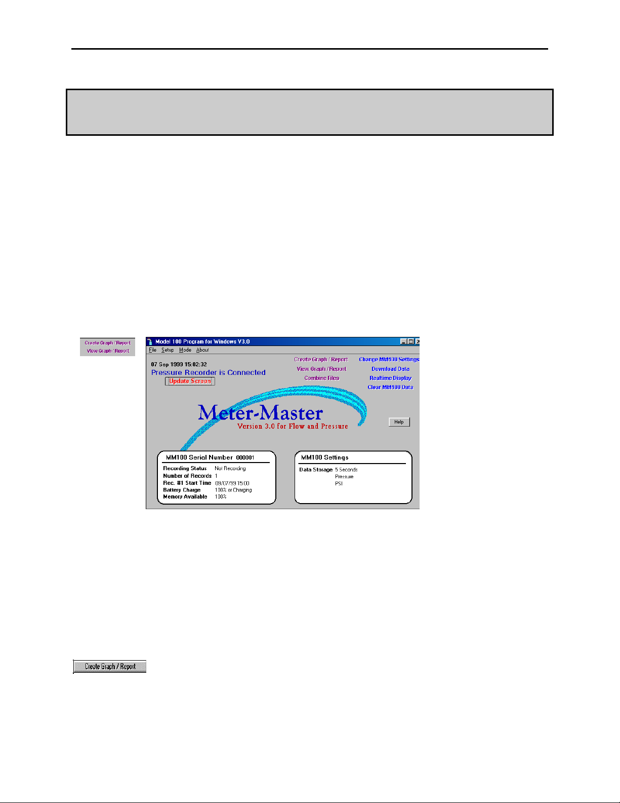
To Access The Model 100 Program:
1. Connect the Model 100P to your computer and enter the Model 100
Program.
2. Enter the Model 100 Program by selecting the Meter-Master for Windows
program group and then selecting MMV31.
3. Once the Main Screen appears, click on “Update Screen”.
4. Check to ensure that “Pressure Recorder is Connected” appears at upper
left of the Main Screen. If the screen indicates that the Meter-Master is not
connected, see on-screen “Help” (click on “Help” button) or see Section 5.3
in the Troubleshooting chapter of this manual.
To Clear Meter-Master Memory Of Prior Records:
• Click on “Clear MM100 Data”.
To Recharge The Meter-Master Batteries:
1. Connect the battery charger. (Whenever the Model 100P is not in the field,
it should remain connected to the charger continuously.)
2. Recharge overnight. If the Meter-Master has powered down due to low
battery, recharge for at least 14 hours. Power-down is indicated by a 6
second alternating long-short flash on the Meter-Master rocker switch LED
when the switch is toggled ON from the OFF position.
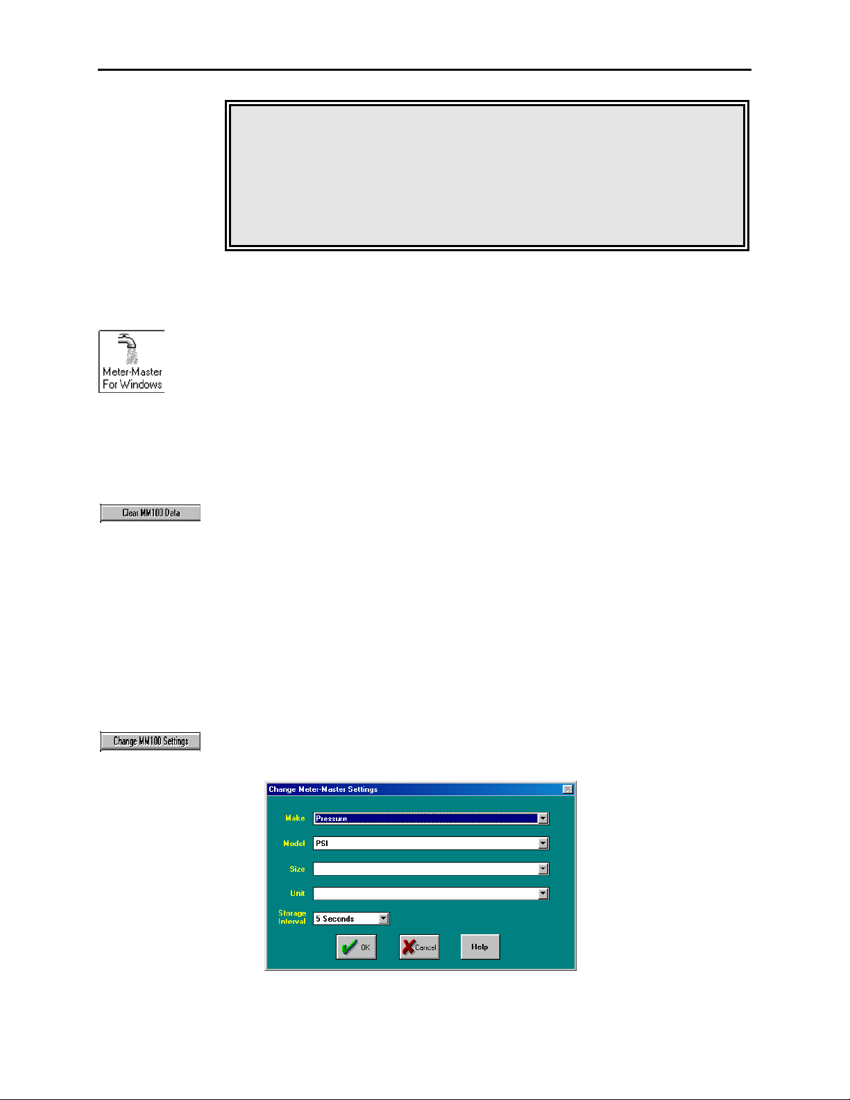
To Change Data Storage Interval:
1. Make sure that you are at the Main Screen and that you are connected to the
Meter-Master (see above).
2. Click on “Change MM100 Settings”.
3. Select the desired Data Storage Interval.

2.1 COLLECTING DATA: Making A Recording page 9
The MM100P will store one pressure recording for each time interval selected.
(see box later in this section, “About The Data Storage Interval”).
Changing the Model 100P settings also automatically sets the Meter-Master
date/time to the computer date/time.
Changing The MM100 Settings Erases All Data In The Meter-
Master!! Ensure that you have successfully downloaded the data from
the prior test(s) before continuing.
ABOUT THE DATA STORAGE INTERVAL (1, 5, 10, 30, 60 seconds): Determines the resolution of the
Meter-Master data file (*.MDB) from which all subsequent graphs and reports are created. This is the
resolution of the original data recorded by the Meter-Master in the field: the shorter the interval, the greater
the detail possible in subsequent graphs and reports. For example, a data storage interval of 10 seconds
samples the pressure once every 10 seconds and allows accurate data analysis for periods of 10 seconds or
longer. The Data Storage Interval is chosen before the Meter-Master goes into the field.
This interval effects the size of the data file and the length of time you can record before running out of
memory. The same test recorded with a 5 second interval will take up six times more memory in the Meter-
Master than one stored with a 30 second interval. The recording times for the 5 intervals are: 1 sec. interval
= 1.5 days; 5 sec = 7.5 days; 10 sec. = 15 days; 30 sec. = 45 days; 60 sec. = 90 days.
Choosing the Data Storage Interval: The interval selected depends on the desired resolution of the recorded
data. Should you find you want more detail, shorten the interval; if you want to record for longer time
periods, lengthen the interval.
ABOUT MULTIPLE TESTS:The Model 100P can hold up to 20 individual records (brief records of less
than one Data Storage Interval in length are ignored). As long as there is still room in the Meter-Master
memory for the additional data you wish to collect, you may end a Meter-Master recording and move the
Meter-Master to a new location, attach the hose, and then start a new record.
TO BEGIN A TEST
1. Check Sensor Port And Hose For Obstructions.
Before connecting pressure hose to sensor port, make sure no mud or other debris
obstructs the openings. To clean sensor port, flush with water. Do not use anything
pointed or hard (e.g., metal wire) to dig dirt out of sensor port. Use a pliable
implement, like a Q-Tip or a straw.
2. Set Zero Pressure (if necessary).
Make sure the Meter-Master hose connection (quick connect fitting on front of unit)
is open to the atmosphere. Press the rocker switch ON for about 20 seconds until the
LED turns on. (If the LED turns on when you first press the switch, wait until it
turns off then on again.) The Meter-Master will take a pressure reading and adjust its
zero pressure value accordingly. Turn recording OFF again until you are ready to

page 10 2.1 COLLECTING DATA: Making A Recording
begin recording. You do not need to zero the pressure again until you are recording
in an area where the local atmospheric pressure is meaningfully different.
WARNING: PRESSING THE ROCKER SWITCH FOR 20 SECONDS (AS
DESCRIBED ABOVE) RESETS THE DEFAULTS AND ERASES ALL DATA!
3. Secure The Hose To The Pipe.
The Meter-Master hose comes with a 1/4” NPT male fitting (with a female adapter)
to attach to a pipe fitting. Attach the hose to the pipe, then vent the air in the hose by
briefly opening the valve controlling flow from the pipe. If you have selected the
carbon steel quick connect fittings with the relief valve, use the relief valve.
4. Attach The Hose To The Meter-Master.
Pull back the ring on the female coupler at the end of the hose and press onto the
male coupler attached to the unit.
5. Turn Meter-Master Recording On.
Press and release the ON side of the rocker switch (with the LED). The switch will
automatically return to its center position. The LED will light for approximately 3
seconds indicating that the recording session has begun.
If the unit was just recharged after a power-down state, recording will start 3 minutes
after being turned on in order to allow time for the electronics to settle. When
turning the instrument on after it has powered-down, make sure to depress the ON
side of the rocker switch completely and then let it return to its center position. In
normal operation (unit has not powered-down due to low battery), it is not necessary
to push the switch beyond the center position when starting a recording.
Low Battery Signal: If the signal light displays alternating long-short
flashes for six seconds, the batteries are low and the instrument has
powered-down. Recording is not possible without first recharging the
batteries.
6. Verify Sensor Operation.
After the recording has begun, press the ON side of the switch again. The signal
light will flash once for each 10 psi of pressure or portion thereof (see table below).
Checking the Pressure: You may check the pressure at any time without
interrupting the current recording by pressing the ON (LED) side of the
switch again. The signal light flashes once for each 10 psi or portion
thereof. The LED does not flash for pressures less than 1 psi.
number number
psi range of flashes psi range of flashes
0.00 - 0.99 0 40.00 - 49.99 5
1.00 - 9.99 1 50.00 - 59.99 6

2.1 COLLECTING DATA: Making A Recording page 11
10.00 - 19.99 2 60.00 - 69.99 7
20.00 - 29.99 3 . . . - . . . . . .
30.00 - 39.99 4 290.00 - 299.99 30
If the pressure indicated by the flashing LED does not seem consistent with the
pressure anticipated, verify the hose connection. Ensure that there is no dirt or debris
in the hose or any of the fittings. Ensure that the valve controlling flow from the pipe
is open.
TO END A TEST
1. If Desired, Confirm Sensor Operation.
Before ending the recording session, you may test the sensor to verify that the Meter-
Master is still operating properly by pushing the ON (LED) side of the switch again
(see above, “Verify Sensor Operation”).
2. Turn Meter-Master Recording Off.
Push rocker switch to OFF position.
3. Unscrew The Hose From The Pipe Fitting.
Close the valve controlling flow from the pipe. Unscrew the hose slowly to allow
pressure to release. After disconnecting the hose from the pipe, the hose will
uncouple easily from the Meter-Master.
4. Remove All Equipment From The Site.

page 12 2.2 COLLECTING DATA: Downloading Data And Adding Customer Information
2.2 Downloading Data And Adding Customer
Information
The Downloading Data routine transfers Meter-Master data to your computer and enables
you to add customer information to the data file. The Meter-Master holds up to 20
records at a time; you may download them in any order and multiple times. The dialog
box indicates whether or not each record in the MM100 has been downloaded. The
customer information may be edited later when creating a graph or report.
TO DOWNLOAD DATA AND ADD CUSTOMER INFORMATION
1. Connect The Meter-Master To Computer And, If Possible, To Battery
Charger; Enter The Model 100 Program.
Click on “Update Screen” to confirm connection to the Meter-Master. “Pressure
Recorder is Connected” should appear on the Main Screen. If not, refer to Chapter 5,
“Troubleshooting”. The Meter-Master should not be recording (rocker switch should
be in the OFF position).
Whenever the instrument is in the office, it is good practice to leave it connected to
the battery charger. Batteries last longer if they are charged often and stored attached
to the charger.
2. On The Main Screen, Click On “Download Data” Button.
Clicking on Download Data brings up the Meter-Master Download Screen.
3. Verify Dates/Times.
If any record start date/time is not correct, double click on each incorrect date/time
and edit. Make sure you maintain the exact same format. You may also permanently
fix the start date/time when you create a graph or report (see Section 3.4, “Data Grid
And Customer Information Screen”).

2.2 COLLECTING DATA: Downloading Data And Adding Customer Information page 13
4. Select Record To Download.
Click on column to left of record desired. If any short records were created
inadvertently, you can identify the record you want by the large number of intervals.
A short record will have only a few intervals.
5. Enter File Name.
File names have a maximum of 8 characters; an “.mdb” extension will automatically
be added if you do not include one. Do not use an existing file name. Use letters and
numbers; do not use the space bar or punctuation symbols. You can download to any
directory desired. Click on “OK” when done. (Click on “Exit” if you do not want to
continue with the download procedure.) After entering the filename, the data will
take a few moments to download.
6. Add Customer Information.
After the record is downloaded into your computer, the Customer Information Screen
appears. Use the Tab key or mouse to select items, then enter information. The
Customer Information Screen may also be edited later through the Create
Graph/Report procedure (Section 3.4). You must enter a "Location/Meter ID"; the
program uses this number to identify the file later.
7. Click On "OK" Button When Finished.
8. Repeat Steps 4-7.
Repeat the above routine until all desired records are downloaded, then exit.
9. If Desired, Initialize For Next Test.
Once downloading has been completed, you may prepare for the next recording. If
you wish to change the data storage interval, click on “Change MM100 Settings” on
the Main Screen to clear current stored records and to initialize for a new test. If the
data storage interval is to remain the same, clicking on “Clear MM100 Data” will

page 14 2.2 COLLECTING DATA: Downloading Data And Adding Customer Information
clear the current Meter-Master records. If desired, you can store more data without
clearing records as long as there is adequate memory available.
3.1 GRAPHS AND REPORTS: Overview: Creating, Printing, Saving, Exporting, Viewing page 15
Chapter Three
GRAPHS AND REPORTS
3.1 Overview: Creating, Printing, Saving, Exporting,
Viewing
Create Graph/Report: Generates, prints, saves, and exports graphs and reports from a
data file in a variety of styles.
View Graph/Report: Displays graphs and reports that you have previously created and
saved or exported.
For customizing graphs and for customizing and exporting reports to other applications,
see the sections following this one.
TO CREATE A GRAPH OR REPORT
1. Enter The Create Graph/Report Procedure by clicking on the Create
Graph/Report button on the Main Screen.
The Select File Dialog Box appears.
2. Select The Desired Data File (*.MDB).
In the Select File Dialog Box, choose a data file; Meter-Master data files have a
*.mdb extension. You may select a file in any drive or directory.

page 16 3.1 GRAPHS AND REPORTS: Overview: Creating, Printing, Saving, Exporting, Viewing
Once you have selected a downloaded file, click on “OK”. The Display Options
Dialog Box appears.
3. Select Display Options.
The Display Options Dialog Box controls general features of the data display.
• Choose An Output Format. In the Display Dialog Box, click on:
• Graph to create a graph.
• Report/Export to create a report and to export data to a third party
program such as MS Word or Excel.
• Choose Among Presentation Options. Click on:
• Max, Avg, Min for graphs/reports showing maximum, average, and
minimum pressure for each grid interval.
• Avg Pressure for graphs/reports showing average pressure for each
grid interval.
• Choose Resolution. Click on:
• Summary to display all data in a condensed format. Graph displays
entire record on one screen.
• Detailed to display all data in an expanded format. Graph shows
entire test on multiple screens with a scroll bar.

3.1 GRAPHS AND REPORTS: Overview: Creating, Printing, Saving, Exporting, Viewing page 17
4. If Desired, Change Data Start Time, Report Start Time, Grid Interval, Or
Edit The Customer Information Screen.
Start Time, End Time, and Grid Interval for graphs and reports are edited on the Data
Grid Screen. Customer information (the file header) is edited on the Customer
Information Screen.
• Changing Graph/Report Resolution: The default graph/report shows
approximately 150 data intervals unless the raw data file has less than 450
intervals, in which case, a smaller number of data intervals are used. If you wish
to increase the number of intervals, click on “Data Grid” and then decrease the
Grid Interval so that more data points are displayed.
• Changing Unit of Measure For Graph/Report: If you would like graphs and
reports to have a different unit of measure, click on “Customer Information” and
then on “Change MM100 Settings” and change the unit of measure to the one
desired.
5. When Done, Click On “OK” To Display Graph Or Report.
6. Working With Graphs and Reports (see following sections).
When the Graph Screen or Report Screen appears, you may scan data and customize,
save, export, and print the graph or report:
To Scan Data:
• Summary Graph: Initial graph shows entire file. Intervals to the right
side of the graph will be condensed if you have significantly decreased the
Grid Interval on the Data Grid. Click once on graph and then use cursor
movement keys (End/Home, Page Up/Down, Up/Down/Right/Left arrows)
to change first interval displayed on graph. Graph will then show the new
first interval through end of record. Double-click on any colored section of
the graph, and a balloon will appear with date/time and values associated
with the two (2) grid intervals closest to that point on the graph. (See also
Section 3.2, “The Graph Screen”.)
• Detailed Graph: Initial graph shows first 12 or so intervals of record.
Place cursor on bottom axis of graph (becomes an up/down arrow) and pull
up approximately half way in order to expose the date/time associated with
each graph interval. Use the scroll bar below x-axis or cursor movement
keys (End/Home, Page Up/Down, Up/Down/Right/Left arrows) to scan the
rest of the record. (See also Section 3.2.)
• Reports: To scan report, use scroll bar on right of window or cursor
movement keys (End/Home, Page Up/Down, Up/Down/Right/Left arrows).
There are also buttons for page changing on top of the window. (See also
Section 3.3, “The Report Screen And Exporting”.)
To Print A Graph Or Report:
• Click on “printer” button. For landscape printing, you must select
landscape in your Windows printer control.

page 18 3.1 GRAPHS AND REPORTS: Overview: Creating, Printing, Saving, Exporting, Viewing
To Save A Graph/Report To A File:
• Graphs: Click on “diskette” button (2nd button from left). Enter a
filename (max. 8 characters); the program will automatically add a “.chf”
extension. Change drive/directory if desired.
• Reports: Click on “envelope” button at the top of the window. Select
desired file format from options displayed. Enter filename; change drive
and directory if desired.
To Export Data To Another Application (Report Routine):
• Click on “envelope” button at the top of the report window. Select desired
application from options displayed, e.g., Lotus, Excel, Quattro Pro,
WordPerfect, or MS Word. Enter filename, change drive and directory if
desired.
TO VIEW SAVED GRAPHS AND REPORTS
1. Click On "View Graph/Report" Button On Main Screen.
After clicking on “View Graph/Report”, the Select File Dialog Box will appear.
2. Select An Existing File (e.g., *.CHF, *.XLC, *.DOC).
Once a file is selected, it will open in whatever format it was saved.
• Graph File: Graph files (*.CHF) open within the Meter-Master graphic
software described above and in the next section. You may modify the
appearance of the graph, but not the display options, customer information,
and data grid.
• Report File: A report may be opened in the appropriate application (e.g.,
Excel, Microsoft Word, WordPerfect) from within the Model 100 Program
software, as long as the Model 100 Program directory, the report file’s
directory, and the third-party program directory are all on the current PATH in
your AUTOEXEC.BAT file. Alternatively, you can access files exported to
other applications (third-party programs) through the applications themselves.
Table of contents
Other Meter-Master Measuring Instrument manuals


Popular Measuring Instrument manuals by other brands

ITS Telecom
ITS Telecom P790 operating instructions

Acrel
Acrel AIM-T500L Series Installation and operation manual

Extech Instruments
Extech Instruments SDL310 user guide

Guralp Systems
Guralp Systems CMG-DM16R8 operating guide

OpenEye
OpenEye ME Series Hardware manual

Inficon
Inficon Sensistor ILS500 operating manual


