METER ATMOS 41 Use and care manual

METER Group, Inc. USA
2365 NE Hopkins Court, Pullman,WA 99163
T +1.509.332.2756 F +1.509.332.5158
E info@metergroup.com W metergroup.com
ATMOS 41 RAIN FUNNEL AND PYRANOMETER REPLACEMENT
Tools Needed
Preparation
Install New Rain Funnel
Update PYR Calibration Factor
Update with a ZSC Bluetooth® Sensor Interface
Update with a ZL6 or EM60 Data Logger
Update with a PROCHECK Handheld Reader
Update with a Campbell Scientific Data Logger
Verify Rain Funnel Installation
Customer Support
Use the following instructions to install a replacement funnel and pyronometer for the ATMOS 41 All-in-One Weather
Station. Please contact Customer Support to order the ATMOS 41 funnel with pyranometer solar sensor.
TOOLS NEEDED
Data logger or
handheld reader
METER ZSC, ZL6, EM60, PROCHECK, Campbell Scientific, Inc. (CSI)
Must be capable of issuing SDI-12 extended commands
Cable
Micro-USB
USB-to-RS232
NOTE: ZSC does not require cables.
Connect from laptop to ZL6 or EM60
Connect from laptop to PROCHECK or CSI data logger
Software USB cable adapter driver (if applicable)
METER ZSC
METER ZL6, or EM60
METER PROCHECK
CSI data logger
ZENTRA Utility Mobile
ZENTRA Utility software
TeraTerm software
LoggerNet software
Sharp-pointed object Use to push tabs in when disconnecting pyranometer connector (e.g., ball-point pen)
Rain funnel (PN 20269) Has the new pyranometer (PYR) solar sensor installed
NOTE: Part number 20269 is for the rain funnel model with waterproof connector and strain relief cable
(serial number newer than ATM-410002462). If an older model is needed, please request the older style
from Customer Support.
PREPARATION
1. Download the software needed to connect the ATMOS41 with the new rain funnel to a laptop or smart device
(phone, tablet).
2. Carefully read this document all the way through.
Figure1 shows an image of the new model with waterproof connector and cable strain relief and the old model.
18339-00
4.10.2020
2
New model with waterproof
connector and cable strain relief Old model
Figure1 Rain funnel and pyronometer connector
INSTALL NEW RAIN FUNNEL
The instructions below explain how to remove the old rain funnel and install the new rain funnel with a waterproof
connector and cable strain relief.
1. Unplug the ATMOS 41 from the data logger or reader.
2. Touch any conductive material connected to the ground to discharge static electricity from the body (e.g.,metal pole).
CAUTION: Electrostatic discharge (ESD) can damage ATMOS 41 electronics.
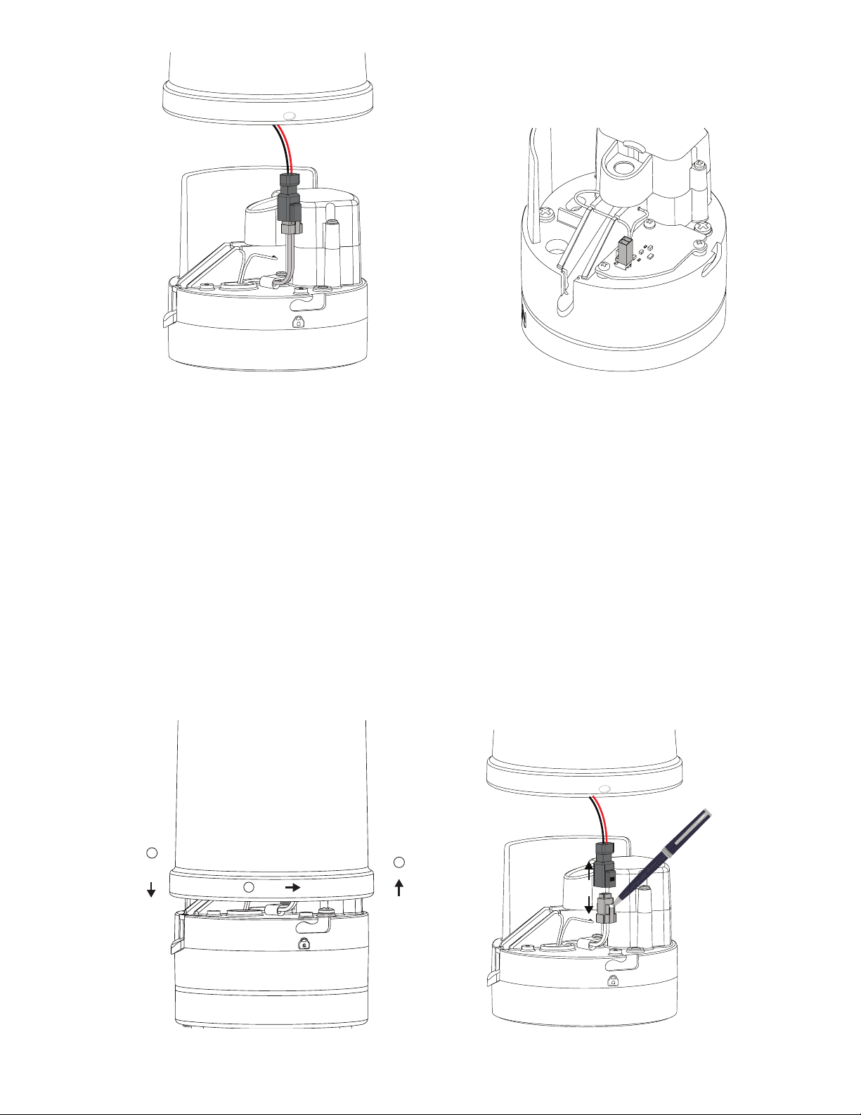
3. Press and hold the rain funnel down to compress the internal spring.
4. Twist counter-clockwise to unlock from the ATMOS 41 base (Figure2).
5. Carefully lift the funnel just enought to reach the pyranometer connector.
6. Press in the tabs on both sides of the connector locking mechanism with an object with a sharp point (e.g.,aball-
point pen, Figure3).
NOTE: If the rain funnel pyranometer connect does not look like the one in Figure3, just pull the connectors apart.
1
3
2
Push
down Pull up
Rotate
Figure2 Removing ATMOS 41 rain funnel
Use a sharp point
to push down on the tab
to release the connectors
Figure3 Disconnect pyronometer connector
3
7. After the tabs are released, pull the connectors apart
and remove the funnel.
The funnel just removed may be discarded.
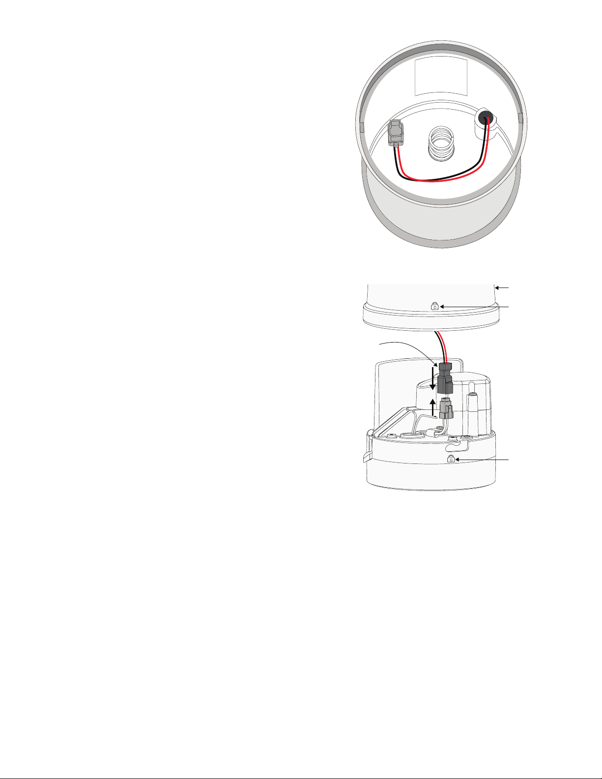
8. Write down the calibration factor (CAL Factor) for the
new pyranometer, located on the inside of the new
funnel (Figure4).
9. Connect the new rain funnel pyranometer cable
connector to the ATMOS41 connector (Figure5).
Make sure the cable does not get pinched by the
spring or interfere with the raindrop path to the gold
electrodes.
NOTE: The connector is keyed and will only connect if oriented
correctly.
P/N: 2335
S/N: 2294
CAL FACTOR
5.86 W m2
Figure4 CAL Factor for new pyranometer sensor
New rain funnel
PYR connector
Lock symbol
Lock symbol
Figure5 Pyranometer cable connector

4
10. Line up the pegs on the inside of the funnel with the
notches on the ATMOS 41 (Figure6).
11. Press down and turn the rain funnel clockwise.
On newer ATMOS 41 designs, the gray lock symbol on
the rain funnel should be lined up with the lock symbol
molded into the ATMOS 41 base (Figure5).
Peg
Notch
Lock symbol
Figure6 Align new funnel
UPDATE PYR CALIBRATION FACTOR
This section describes how to connect to an ATMOS 41 and update the pyranometer CAL Factor using various data
acquisition devices. The CAL Factor is located inside the rain funnel and should have been written down before
attaching the new rain funnel.
GO TO—
Update with a ZSC Bluetooth® Sensor Interface
Update with a ZL6 or EM60 Data Logger
Update with a PROCHECK Handheld Reader
Update with a Campbell Scientific Data Logger
5
UPDATE WITH A ZSC BLUETOOTH®SENSOR INTERFACE
The following instructions explain how to connect to an ATMOS41 and update the pyranometer CAL Factor using a ZSC and
ZENTRA Utility Mobile.
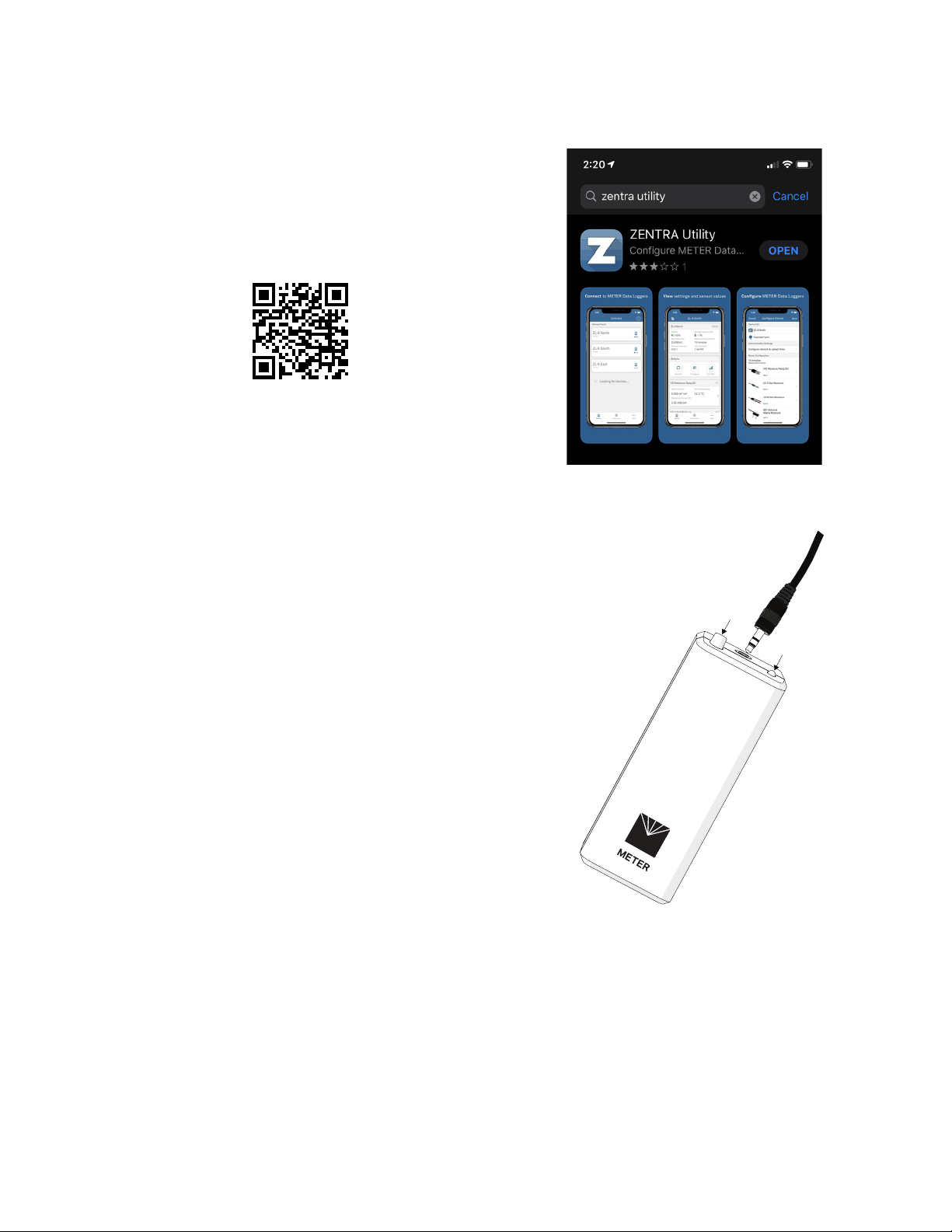
1. Download ZENTRA Utility for iOS or Android
mobiledevice.
Either scan the QR code shown in Figure7 to access
the ZENTRA Apps website or search for ZENTRA Utility
in the appropriate app store (Figure8).
Skip this step if ZENTRA Utility is already loaded.
Figure7 QR code to ZENTRA Apps website
2. Plug the sensor stereo connector into the ZSC stereo
port (Figure9).
3. Press the button on the ZSC.
4. Confirm that the LED on the ZSC begins blinking blue.
Figure8 ZENTRA Utility in mobile app
Button
LED
Figure9 Plug sensor stereo connector into ZSC

6
5. Open ZENTRA Utility on mobile device.
Figure10 shows the Connect screen on a mobile device.
ZENTRA Utility Mobile will search for and display nearby
Bluetooth-enabled ZENTRA devices.
6. Press the ZSC (Figure11) to establish a Bluetooth
connection (in this example, Adrian’s ZSC).
Figure12 shows the ZSC making a connection with the
ATMOS 41.
Once a connection is made, the ZSC main screen
will appear (Figure13). The ZSC is now connected to
the ATMOS41 and ready to update the pyranometer
CALFactor. Figure10 Connect screen
Figure11 ZENTRA Utility window
Figure12 Establishing Bluetooth connection

7
7. Press the Update ZSC firmware button (Figure13) to update to the most current firmware, if needed.
8. Scroll down to see the Sensor Information (Figure14).
9. Press the menu dots located in the lower right-hand corner of the ZSC screen (Figure14) to open the More screen.
10. Select Sensor Tools on the More screen (Figure15) to open the Sensor Tools screen.
11. In the Sensor Tools screen, press on the ATMOS 41 Pyranometer Calibration button (Figure16).
This will bring up the ATMOS 41 Pyranometer Calibration screen.
Figure13 Update ZSC firmware Figure14 View ATMOS41 data
Figure15 Sensor More screen
Figure16 Sensor Tools screen
8
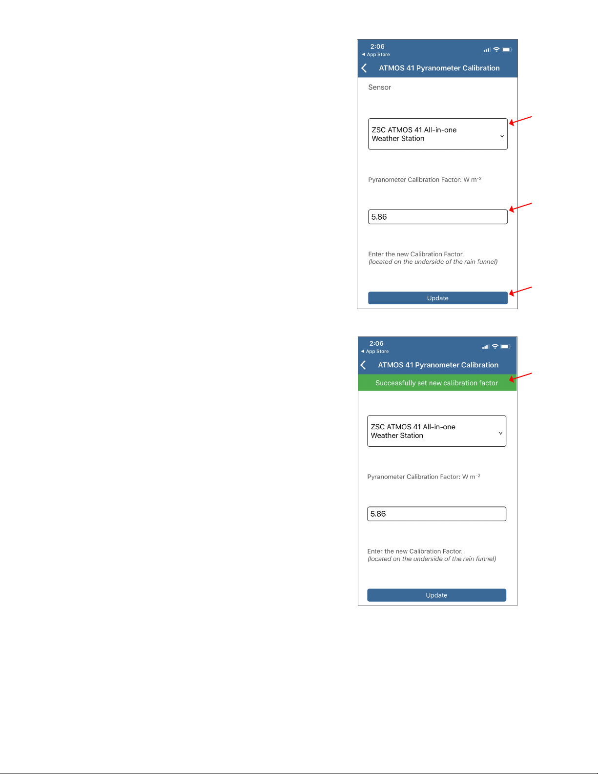
12. Confirm that the ZSC ATMOS 41 All-in-one Weather
Station is the sensor listed (Figure17).
13. In the text box below the label Pyranometer
Calibration Factor : W ·m-2(Figure17), enter the new
pyranometer CAL Factor printed on a label inside the
ATMOS41 replacement funnel (Figure6).
14. Press the Update button.
15. Verify the ATMOS 41 Pyranometer Calibration screen
returns the following message (Figure18):
Successfully set new calibration factor
16. Proceed to Verify Rain Funnel Installation to complete
the process and put the ATMOS 41 back in service.
Figure17 Enter CAL Factor value
Figure18 Verify CAL Factor value
9
UPDATE WITH A ZL6 OR EM60 DATA LOGGER
The following instructions explain how to connect to an ATMOS41 and update the pyranometer CAL Factor using a
METER ZL6 or EM60 data logger. Please go to metergroup.com/downloads and download the most current data logger
firmware before beginning.
1. Connect the ATMOS 41 to the data logger using the
stereo plug connector.
2. Connect the data logger to a computer with a micro-
USB cable.
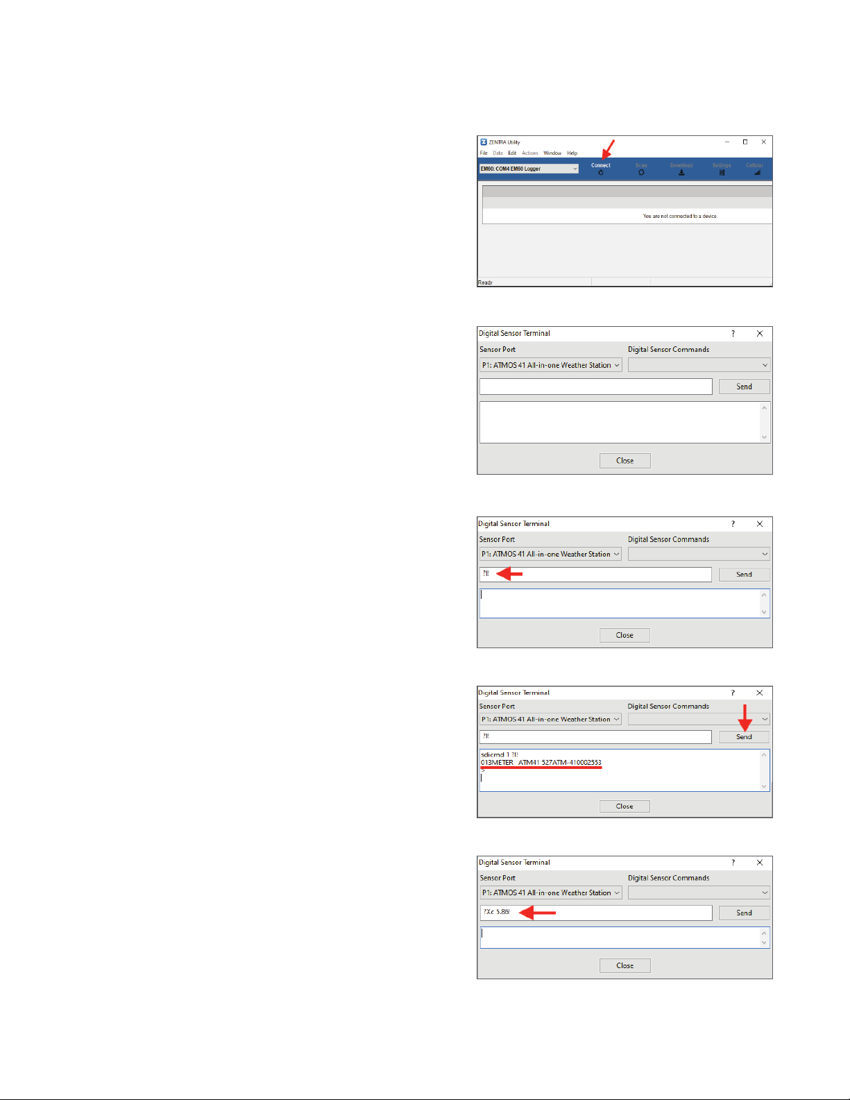
3. Open ZENTRA Utility and click on Connect to connect
to the ZL6 or EM60 data logger (Figure19).
4. Select the correct logger from the COM dropdown
(Figure19).
The data logger should show up with every
connected sensor. Push Scan if the newly connected
ATMOS41 does not show up immediately.
5. On the Menu bar (Figure19), select Actions > Digital
Sensor Terminal.
The Digital Sensor Terminal window will appear
(Figure20).
6. Select the correct sensor port from the Sensor Port
dropdown list.
7. Enter the ?I! command in the prompt field (Figure21).
NOTE: Erase previous command from the prompt field first, if
oneappears.
8. Click the Send button to return sensor information
(Figure22).
When SDI-12 address is 0, the returned output should
be similar to 013METER ATM41 XXXATM-41000XXXX
(Figure22).
9. Enter the ?Xc Y.YY! command in the prompt field
where Y.YY is the new pyronometer CAL Factor
(Figure23).
NOTE: Erase previous command from the prompt field first, if
oneappears.
The new pyranometer CAL Factor is printed on a label
inside the ATMOS41 replacement funnel (Figure6).
Figure19 Connect to ZL6 or EM60
Figure20 Digital Sensor Terminal in ZENTRA Utility
Figure21 ?I! command entered
Figure22 ?I! command response
Figure23 ?Xc Y.YY! command entered
10
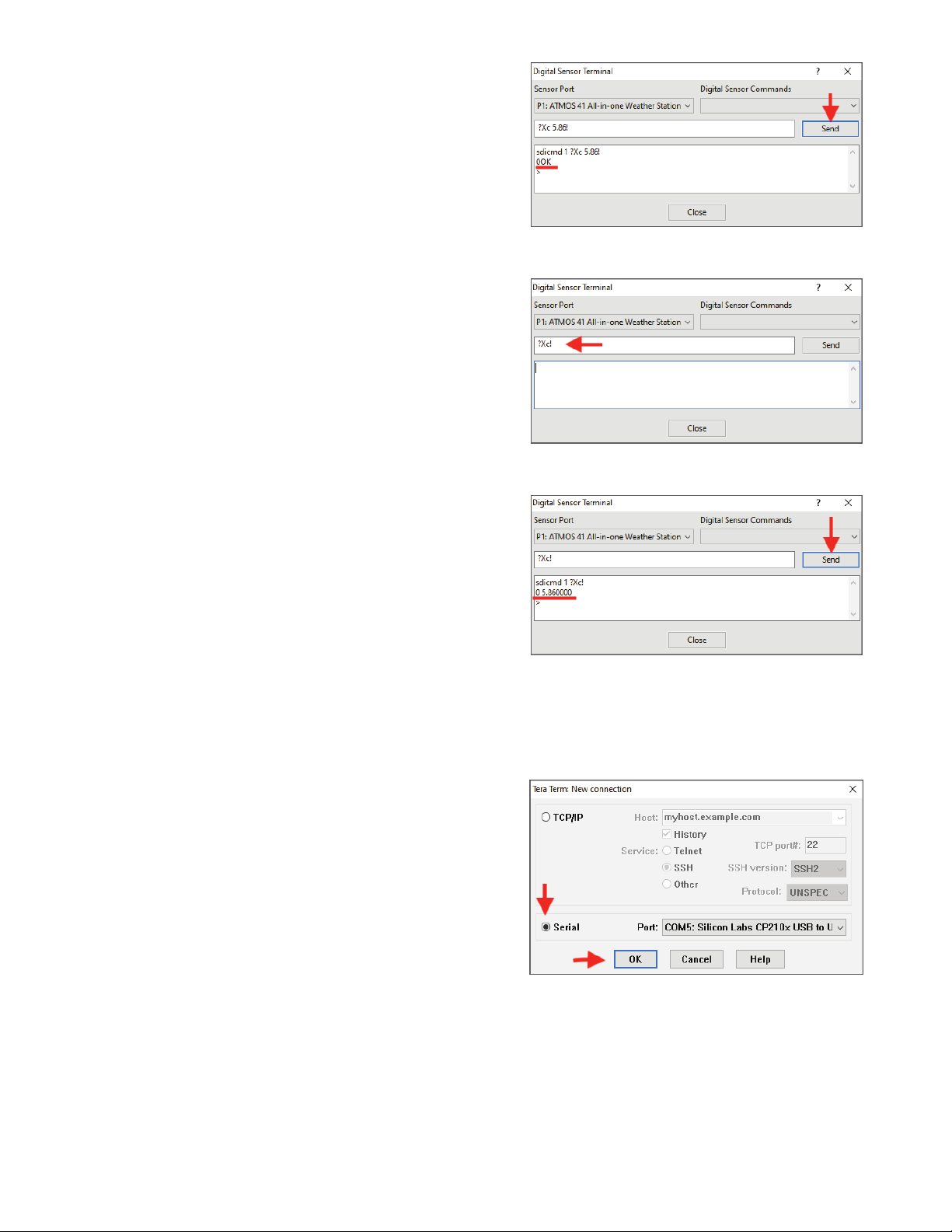
10. Click the Send button to enter the new CAL Factor.
The returned output should be 0OK (zero, capital o,
capital k) (Figure24).
11. Enter the ?Xc! command in the prompt field to verify
the CAL Factor value was entered correctly (Figure25).
NOTE: Erase previous command from the prompt field first, if
oneappears.
12. Click on the Send button.
The response should be the new CAL Factor value
entered in step9. Figure26 shows the ATMOS
41 returning a CAL Factor of 5.86.
13. Proceed to Verify Rain Funnel Installation to complete
the process and put the ATMOS 41 back in service.
Figure24 ?Xc Y.YY! command response
Figure25 ?Xc! command to verify CAL Factor, entered
Figure26 ?Xc! command verified CAL Factor, response
UPDATE WITH A PROCHECK HANDHELD READER
The following instructions explain how to connect to an ATMOS41 and update the pyranometer CAL Factor using a
PROCHECK handheld reader.
1. Connect the ATMOS 41 stereo plug connector into the
PROCHECK stereo port.
2. Connect the PROCHECK to a computer with a
USB-to-RS232 cable adapter.
3. Open Tera Term (Figure27).
4. Select the radio button next to Serial in the New
Connection window.
5. Select the correct COM Port from the dropdown list
next toPort.
6. Click on the OK button. Figure27 New connection
11
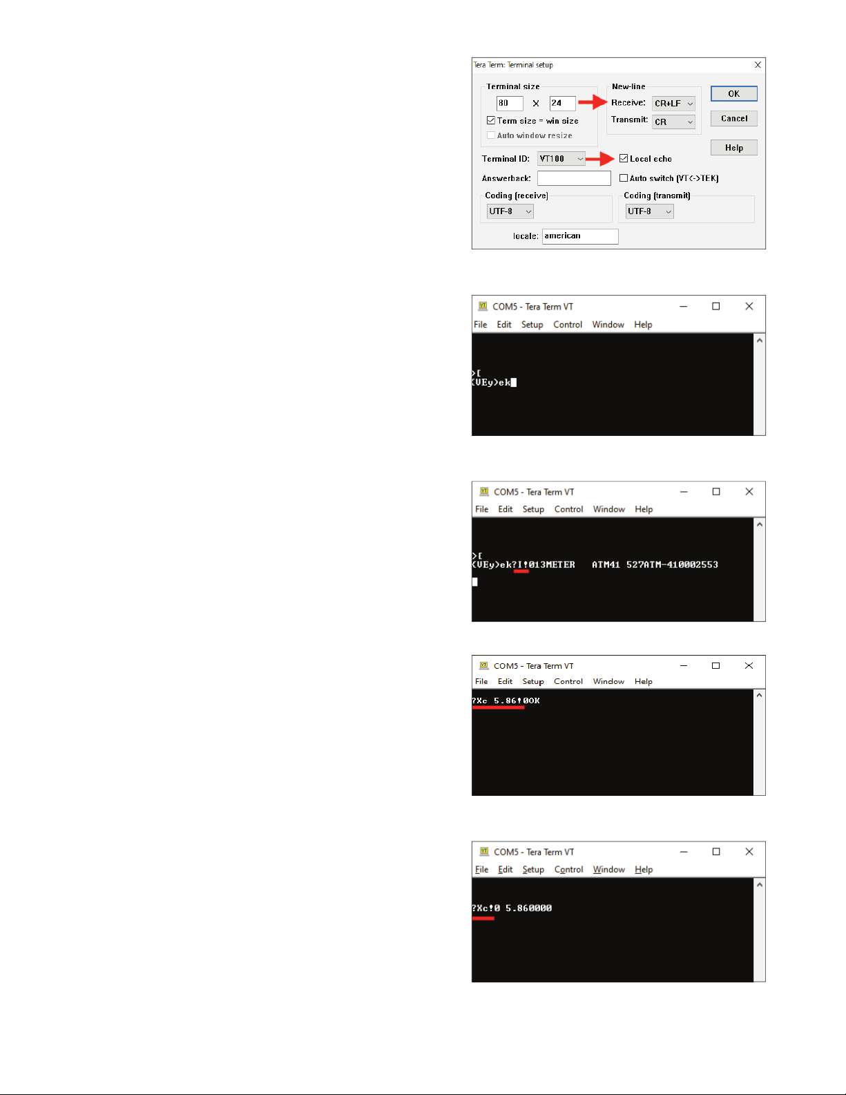
7. Click on the Setup menu item at the top of the window
and selectTerminal.
This opens the Tera Term Terminal setup window
shown in Figure28.
8. In the New-line area of the Terminal setup dialog box
do the following:
a. SelectCR+LF from the Receive: dropdown list.
b. Leave Transmit: set to CR.
c. Click the Local echo checkbox to select.
d. Click the OK button (upper right corner).
9. Type [in the COM window (Figure29) to enter the
direct communications mode on the PROCHECK when
connected to the ATMOS41.
When the sensor address is 0, the returned
DDI string will look like a random string of
characters (e.g., {UEy)ek)after entering the direct
communications mode (Figure29).
10. Enter ?I! to view sensor information.
When SDI-12 address is 0, the returned output should
be similar to 013METER ATM41 XXXATM-41000XXXX
(Figure30).
11. Enter ?Xc Y.YY!, where Y.YY is the new pyranometer
CAL Factor.
The new CAL Factor is printed on a label inside the
ATMOS41 replacement funnel (Figure6).
The returned output should be 0OK (zero, capital o,
capital k) (Figure31).
12. Enter the ?Xc! command (Figure32) to verify the new
CAL Factor that was entered in step11.
If the value returned is not correct, repeat step11 and
step12.
13. Proceed to Verify Rain Funnel Installation to complete
the process and put the ATMOS 41 back in service.
Figure28 Terminal setup
Figure29 View sensor information
Figure30 Enter direct communication mode
Figure31 Enter CAL Factor value for replacement funnel
Figure32 Verify CAL Factor value
12
UPDATE WITH A CAMPBELL SCIENTIFIC DATA LOGGER
The following instructions explain how to connect to an ATMOS41 and update the pyranometer CAL Factor using a
Campbell Scientific data logger (this example uses a CR850).
1. Attach a Probe Adapter Pigtail to the ATMOS41 stereo
plug connector.
2. Connect the pigtail wires to the CR850 (orotherCSI
data logger) according to the user manual.
3. Connect the CR850 (or other CSI data logger) to a
computer with a USB-to-RS232 cable adapter.
4. Update the data logger firmware at campbellsci.com,if
needed.
Go to product page and downloads (e.g., campbellsci.
com/cr850 in this example) and follow CSI instructions.
5. Download the LoggerNet software to the computer if it
is not already on the computer from campbellsci.com/
loggernet-admin.
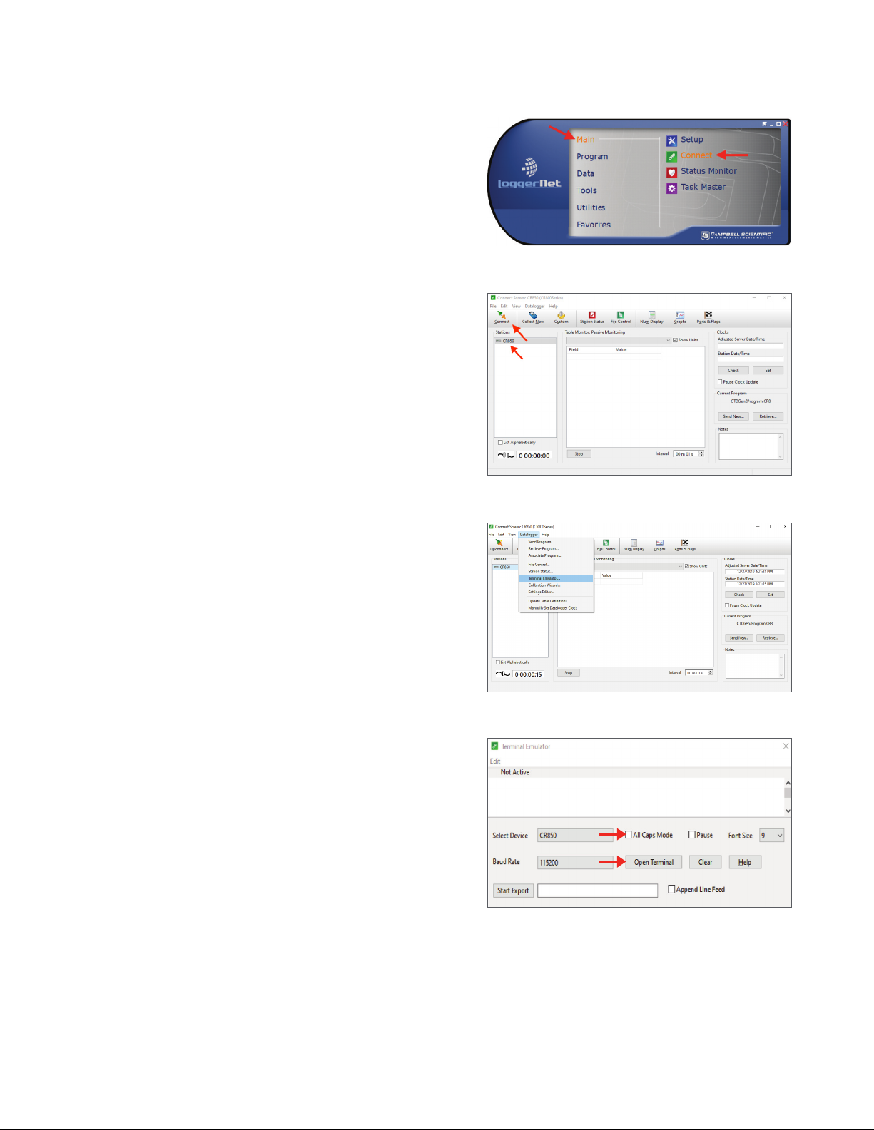
6. Open LoggerNet.
7. Select Connect from the Main menu (Figure33) to enter
the Connect Screen (Figure34).
8. Select the desired data logger listed in the Station
section of the Connection window (CR850 for this
example; Figure34).
9. Click on the Connect button on the Connect Screen
(Figure34).
10. From the top menu bar click on Data Logger >
Terminal Emulator (Figure35).
The Terminal Emulator window will open in a Closed
(not active) state (Figure36).
Figure33 LoggerNet Connect screen
Figure34 Select and connect data logger
Figure35 Open terminal emulator window
Figure36 Terminal emulator window in Closed state
13
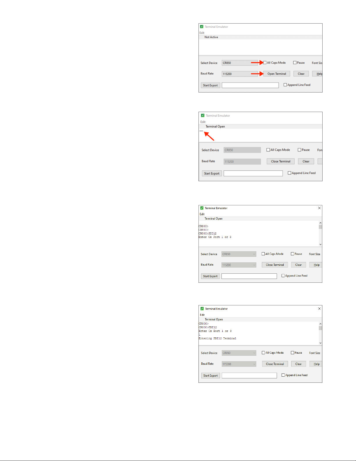
11. Uncheck the All Caps Mode checkbox if it is checked
(Figure37).
12. Click on the Open Terminal button (Figure37).
NOTE: The Closed Terminal and Open Terminal button toggles
between Open Terminal and Close Terminal.
13. Place the cursor in the Open Terminal Emulator window
(Figure38).
14. Press the Enter key a few times.
A CR800> prompt should appear (or the series name of
the data logger being used).
15. Type SDI12 next to the CR800> prompt and press Enter.
NOTE: The data logger will exit this mode relatively quickly, so if a
response is not received,repeat step13 and step15.
The data logger will respond with available ports such
as Enter Cx Port 1, 3, 5, or 7 or something similar
(Figure39).
16. Enter the control port number that the
ATMOS41 sensor is connected to,andpress Enter.
The data logger will respond with Entering
SDI12 Terminal (Figure40).
NOTE: Sensors must be updated individually, so only one sensor may
beconnected to the communications port ata time.
Figure37 Closed Terminal Window
Figure38 Open Terminal window
Figure39 Enter SDI12
Figure40 Set control port
14
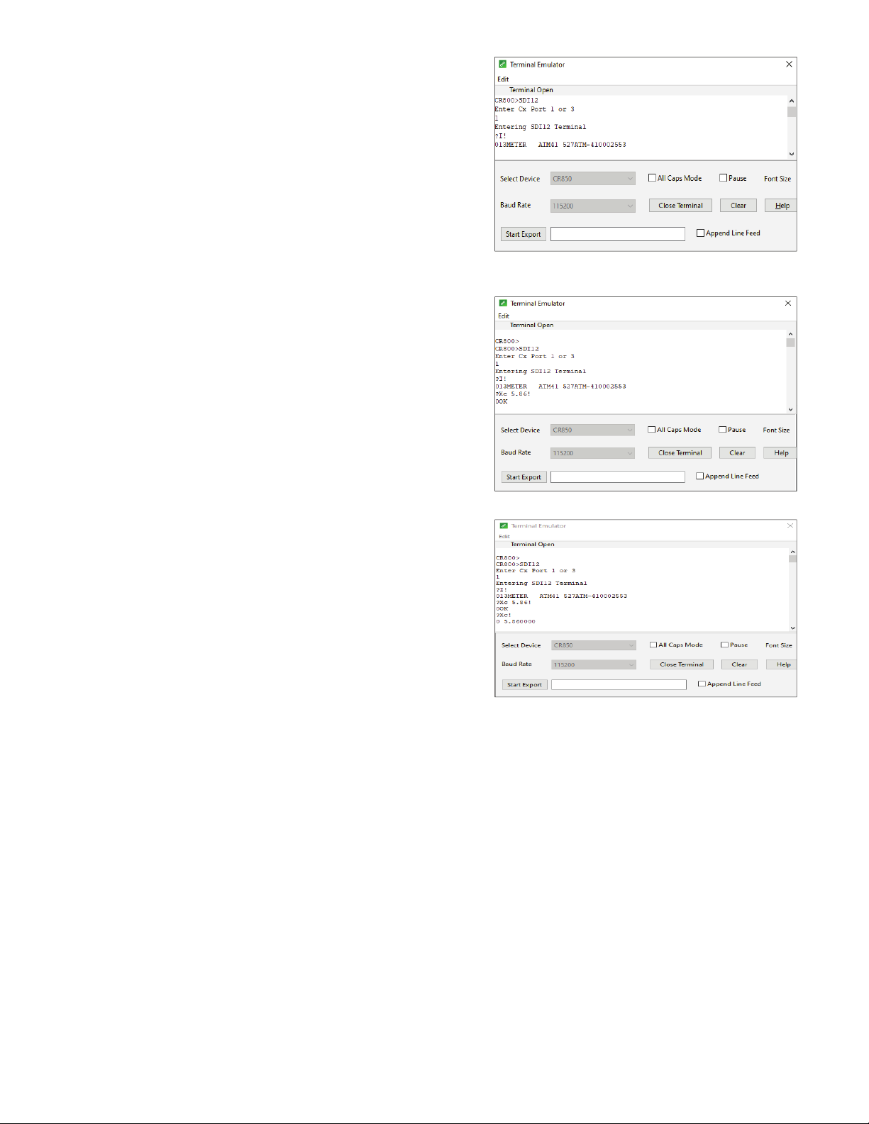
17. Enter the ?I! sensor information command and
pressEnter.
When SDI-12 address is 0, the returned output should
be similar to 013METER ATM41 XXXATM-41000XXXX
(Figure41).
18. Enter ?Xc Y.YY!, where Y.YY is the new pyranometer
CAL Factor.
The new CAL Factor is printed on a label inside the
ATMOS41 replacement funnel (Figure6).
19. Press Enter.
The data logger will respond with 0OK (zero, capital o,
capital k), No answer from sensor, or SDI12 Failed from
the Terminal Emulator screen.
– No answer from sensor—Check to see if the
calibration was successful by entering ?Xc!. If
the CAL Factor returned is the correct (new) one,
command was successful. Otherwise, try entering
?Xc Y.YY! again.
– SDI12 Failed—Close the terminal and disconnect
the data logger. Then repeat step8 through step18.
20. Enter the ?Xc! command and press Enter.
The new CAL Factor entered in step18 should be
returned (Figure43) . If the value returned is different
from the value entered, repeat step18 through step20.
21. Proceed to Verify Rain Funnel Installation to complete
the process and put the ATMOS 41 back in service.
Figure41 Sensor information
Figure42 CAL Factor value
Figure43 Verify CAL Factor value
VERIFY RAIN FUNNEL INSTALLATION
To verify that the ATMOS 41 pyronometer is working properly, follow the steps listed below.
1. Reconnect ATMOS 41 to the correct data logger and port.
2. Check the data and verify that the PYR is providing reasonable data.
3. Ensure that the engraved N is pointing toward True North.
4. Ensure the ATMOS 41 is level (±2 degrees from [0,0]).
This completes the process of replacing the ATMOS41 rain funnel. Please contact Customer Support if you have any
problems any part of these instructions.

15
CUSTOMER SUPPORT
NORTH AMERICA
Customer service representatives are available for questions, problems, or feedback Monday through Friday, 7:00 am to
5:00 pm Pacific time.
Email: support.environment@metergroup.com
sales.environment@metergroup.com
Phone: +1.509.332.5600
Fax: +1.509.332.5158
Website: metergroup.com
EUROPE
Customer service representatives are available for questions, problems, or feedback Monday through Friday, 8:00 to
17:00 Central European time.
Email: support.europe@metergroup.com
sales.europe@metergroup.com
Phone: +49 89 12 66 52 0
Fax: +49 89 12 66 52 20
Website: metergroup.de
If contacting METER by email, please include the following information:
Name
Address
Phone number
Email address
Instrument serial number
Description of problem
NOTE: For products purchased through a distributor, please contact the distributor directly for assistance.
Other manuals for ATMOS 41
5
Table of contents
Other METER Weather Station manuals


