METER ATMOS 41 User manual

ATMOS 41
Distributed & Supported By:
Edaphic Scientific Pty Ltd
www.edaphic.com.au
Ph: 1300 430 928

i
TABLE OF CONTENTS
1. Introduction..............................................................................................1
2. Operation ...................................................................................................3
2.1 Installation ................................................................................................3
2.2 Connecting the ATMOS41..........................................................................5
2.2.1 Safety Precautions ..........................................................................5
2.2.2 Cable Problems................................................................................5
2.3 Connecting to a ZENTRA or EM60 Family Data Logger ...............................6
2.4 Connecting to a Non-METER Logger ..........................................................6
2.5 Pigtail End Wiring.......................................................................................6
2.6 Communication .........................................................................................7
3. System.........................................................................................................9
3.1 Specifications............................................................................................9
3.2 Pyranometer ............................................................................................ 12
3.3 Anemometer ............................................................................................ 13
3.4 Vapor Pressure Sensor............................................................................. 14
3.5 Rain Gauge............................................................................................... 15
3.6 Temperature Sensor................................................................................. 16
3.7 Lightning Sensor...................................................................................... 17
3.8 Compass .................................................................................................. 17
3.9 Configuring the Compass and Lightning Sensor Using ProCheck............. 18
3.9.1 Compass Configuration.................................................................. 18
3.9.2 Lightning Strike Reject Level Configuration................................... 18
3.10 Barometric Sensor ................................................................................. 19
3.11 Tilt Sensor.............................................................................................. 19
18169-00
7.18.2017

ii
3.12 Theory.................................................................................................... 19
3.12.1 Wind Speed and Direction............................................................ 19
3.12.2 Temperature Sensor..................................................................... 21
3.13 Limitations............................................................................................. 23
3.13.1 Snow and Ice Accumulation ......................................................... 23
3.13.2 Heavy Rain and Strong Wind ........................................................ 23
4. Service....................................................................................................... 25
4.1 Calibration ............................................................................................... 25
4.2 Cleaning and Maintenance....................................................................... 25
4.3 Troubleshooting....................................................................................... 27
4.4 Customer Support.................................................................................... 29
4.5 Terms and Conditions .............................................................................. 30
References .................................................................................................... 33
Index ................................................................................................................. 35

1
1. INTRODUCTION
Thank you for choosing the ATMOS41 Compact Weather Station from METER Group, Inc.
The ATMOS41 Compact Weather Station is designed for continuous monitoring of
environmental variables, including all standard weather measurements (see Measurement
Specifications on page 9). The ATMOS41 measures the following:
• solar radiation
• precipitation
• precipitation max intensity
• air temperature
• barometric pressure
• vapor pressure
• relative humidity
• wind speed
• wind direction
• maximum wind gust
• lightning strikes
• lightning distance
• tilt
• compass orientation
WEATHER STATIONS REIMAGINED
All sensors are integrated into a single, small form-factor unit, requiring minimal installation
effort. A robust, no moving parts design that prevents errors because of wear or fouling make
the weather station ideal for long term, remote installations.
Applications of the ATMOS41 are listed below:
• weather monitoring
• microenvironment monitoring
• spatially-distributed environmental monitoring
• crop weather monitoring
• fire danger monitoring/mapping
• weather networks
Additional advantages include its low-power design that supports battery-operated data
loggers, and the SDI-12 three-wire interface. A tilt sensor warns the user of out-of-level
condition, and no configurations are necessary.

3
2. OPERATION
Please read all instructions before operating the ATMOS41 to ensure it performs to its
full potential.
2.1 INSTALLATION
Follow the steps listed in Table 1 to set up the ATMOS41 and start collecting data.
Table 1 Installation
Tools Needed
Wrench 13 mm (1/2 inch)
Secure mounting location
Mount
(if using ATMOS41 compass-corrected wind direction, mount on nonferrous pipe)
• meteorological stand
• pole in cement
• tripod
Diameter: 31.8 to 50.8 mm, 1.25 to 2.0 inch
NOTE: Smaller mounts are compatible if washers are added to the V-bolt (not included).
Standard pipe sizes that are compatible are 1.0-, 1.25-, and 1.5-in diameter pipes. Square
tubing with a width of 1.25 to 2.0 in or T-posts can also work as mounting options.
Preparation
Consider the Surroundings
Avoid obstructions.
Ensure that site selection is far from wind obstruction.
Make sure surrounding objects will not shade the solar radiation sensor.
Conduct System Check
Verify all sensors read within expected ranges (see Section3 onpage 9).
Adjust Pole Height
Many installations require the ATMOS41 to be mounted 2 m above ground, but
this can be adjusted based on the specific application.

4
OPERATION
Table 1 Installation (continued)
Mounting
Install on Mounting Pole
The ATMOS41 is fitted with a V-bolt, allowing it to be mounted on top of most
posts, poles, tripods, etc.
Mount Toward True North
If mounting the ATMOS41 on a ferrous metal post or the compass-corrected
wind direction is OFF, the ATMOS41 must be oriented correctly for accurate
wind direction measurements. An Nengraved on the side of the instrument
should be oriented to point true north (not magnetic north).
NOTE: All ATMOS41 units are shipped with the compass-corrected
wind direction set to OFF.
If mounting on a plastic post, the compass-corrected wind direction can be
turned ON (uses an internal compass; can be turned ON using a ProCheck
(see Section3.9 onpage 18 or SDI-12 command; see the ATMOS41
Integrator’s Guide).
Level the System
Use the bubble level underneath the ATMOS41 or a ProCheck display to level
the weather station. The angle of the mounting pole may need to be adjusted
or shims added to the ATMOS41 pole interface to achieve level. The ATMOS41
must be within approximately ±2 degrees of dead level in both the X and Y
directions to accurately measure rainfall and solar radiation.
Secure the System
Use a wrench to tighten the bolts, securing the ATMOS41 flat and tight against
the top of the stand.
Connecting
Plug Sensor into Data Acquisition System
• Connect the 3.5 mm plug into a ZENTRA or EM60 family of data loggers.
•Configure it to read the ATMOS41 (refer to Section3 onpage 9).
Verify
• Use the SCAN function in the software to show a list of ATMOS41 readings.
• Verify that these readings are within expected ranges.
Third Party Data Loggers
To connect to a non-METER data logger, see the ATMOS41 Integrator’s Guide.
NOTE: ATMOS41 will not work with legacy Decagon data loggers (EM50 Series and EM5B) because the ATMOS41
outputs contain too many parameters.
5
ATMOS 41
2.2 CONNECTING THE ATMOS41
The ATMOS41 Compact Weather Station works most efficiently with a ZENTRA or EM60
data loggers. This system will not work with legacy data loggers (Decagon EM5, EM5B,
EM50, EM50R, EM50G) because the ATMOS41 has too many output parameters (previously
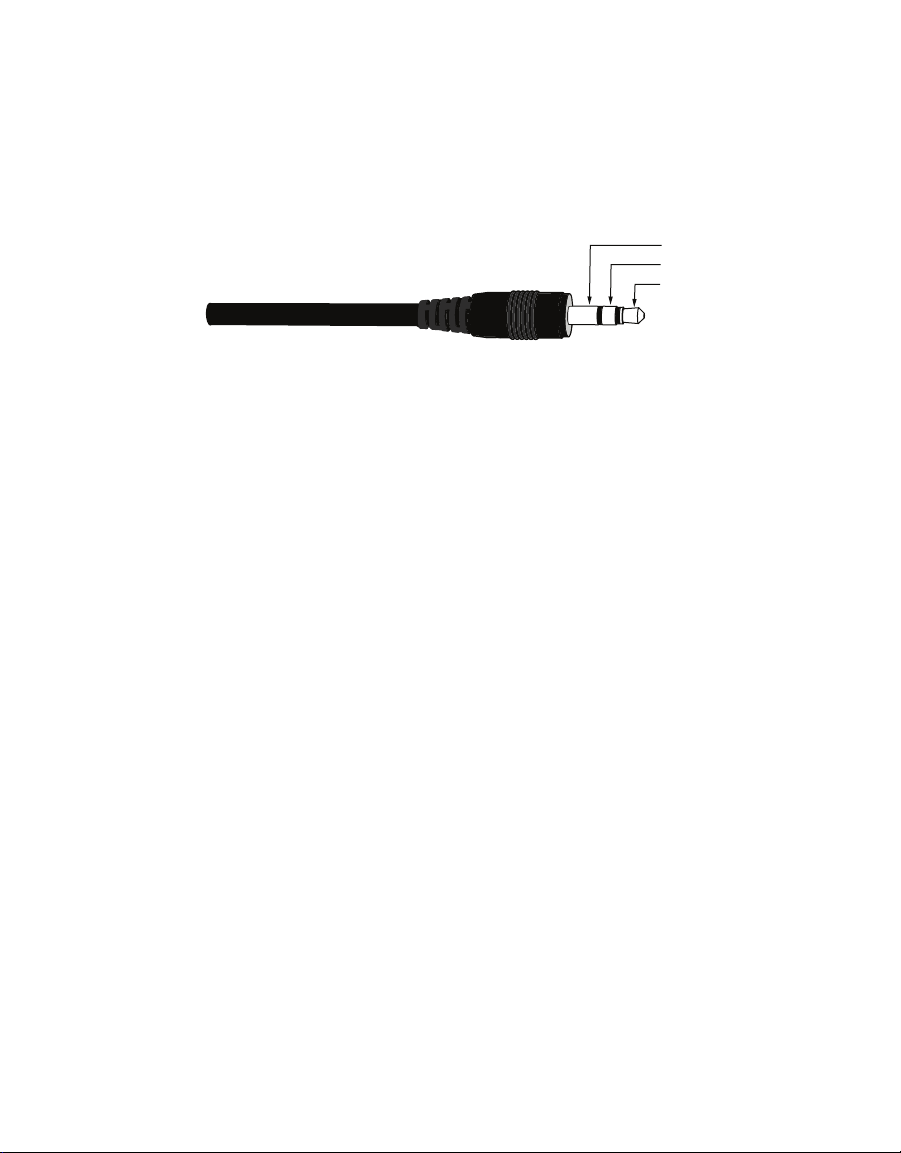
limited to three). The standard station with a 3.5 mm stereo connector (Figure1) connects to
and is configured with a ZENTRA or EM60 data logger.
Ground
Data
Power
Figure1 3.5 mm stereo plug wiring
The ATMOS41 is also compatible with third party loggers and may be purchased with
stripped and tinned wires (pigtail) for terminal connections. For extensive directions on
how to integrate the weather station into third-party loggers, visit https://www.metergroup.
com/environment/products/atmos-41-weather-station/#support to reference the
ATMOS41 Integrator‘s Guide.
The ATMOS41 comes standard with a 5-m cable. It may be purchased with custom cable
lengths for an additional fee (on a per-meter fee basis). METER has successfully tested
digital communication on cable lengths up to 1,000 m (3,200 ft). This option eliminates the
need for splicing the cable (a possible failure point). However, the maximum recommended
length is 75 m.
2.2.1 SAFETY PRECAUTIONS
METER sensors are built to the highest standards, but misuse, improper protection, or
improper installation may damage the sensor and possibly void the manufacturer’s warranty.
Before integrating ATMOS41 or other METER sensors into a system, make sure to follow
the recommended installation instructions and have the proper protections in place to
safeguard sensors from damage.
2.2.2 CABLE PROBLEMS
Improperly protected cables can lead to severed cables or disconnected sensors. Cabling
issues can be caused by many factors, including rodent damage, driving over sensor cables,
tripping over the cable, not leaving enough cable slack during installation, or poor sensor
wiring connections. To relieve strain on the connections and prevent loose cabling from being
inadvertently snagged, gather and secure the cable travelling between the ATMOS41 and the
data acquisition device to the mounting mast in one or more places. Install cables in conduit
or plastic cladding when near the ground to avoid rodent damage. Tie excess cable to the
data logger mast to ensure cable weight does not cause sensor to unplug.
6
OPERATION
2.3 CONNECTING TO A ZENTRA OR EM60 FAMILY DATA LOGGER
The ATMOS41 works seamlessly with ZENTRA or EM60 data loggers. Plug the 3.5 mm stereo
plug connector into one of the six sensor ports.
Once the ATMOS41 has been connected to a ZENTRA or EM60 data logger, configure the
logger port for the ATMOS41, and set the measurement interval. Logger configuration may be
done using either ZENTRA Utility (desktop and mobile) or ZENTRA Cloud (for cell-enabled
ZENTRA data loggers).
To download ATMOS41 data from a ZENTRA or EM60 logger,use ZENTRA Utility or
ZENTRA Cloud.
NOTE: The ATMOS41 draws more current than most other METER sensors because it makes frequent measurements
of wind speed and precipitation. As a result, plugging multiple ATMOS41 stations into a single ZENTRA or EM60 data
loggers may have significant impact on battery life. At times or in regions with plentiful sunshine, the solar
panel should provide ample charge and this should not be an issue. But, during the winter or periods of extended
heavy clouds, the solar panel may not provide enough charging current to keep the system running with multiple
ATMOS41 units. METER recommends using only one ATMOS41 per ZENTRA or EM60 data logger.
2.4 CONNECTING TO A NONMETER LOGGER
The ATMOS41 weather station may be purchased for use with non-METER data loggers.
These sensors typically come configured with stripped and tinned (pigtail) lead wires for
use with screw terminals. Refer to the third-party logger manual for details on wiring.
The ATMOS41 Integrator’s Guide gives detailed instructions on connecting the weather
station to non-METER loggers. Visit https://www.metergroup.com/environment/products/
atmos-41-weather-station/#support to reference the ATMOS41 Integrator’s Guide.
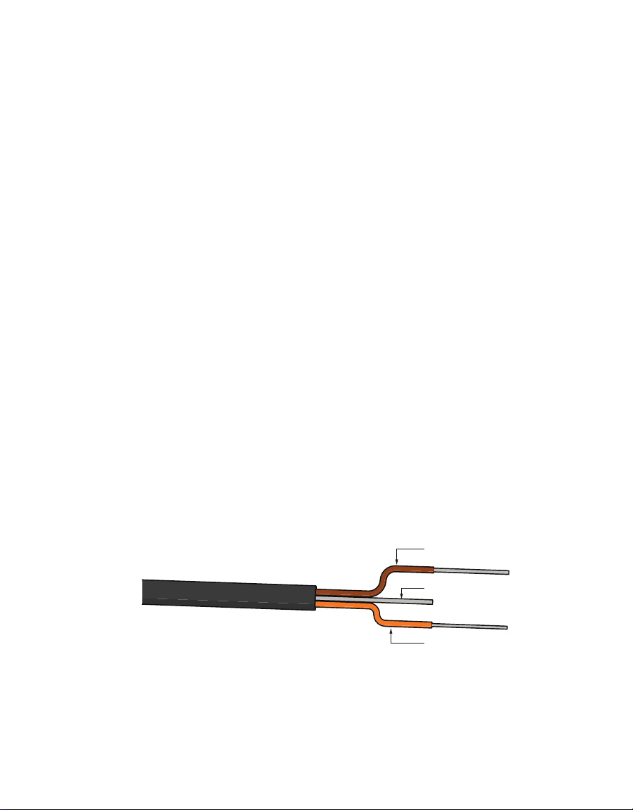
2.5 PIGTAIL END WIRING
Connect the weather station wires to the data logger as illustrated in Figure2, with the
power supply wire (Brown) connected to the excitation, the digital out wire (Orange) to a
digital input, and the bare ground wire to ground.
Ground (Bare)
Data (Orange)
Power (Brown)
Figure2 Pigtail wiring
NOTE: Some early ATMOS41 units may have the older Decagon wiring scheme where the power supply is white,the
digital out is red, and the bare wire is ground.

7
Switched
3.6–15 VDC
Digital
In
Data Logger
G
Data
(orange)
Ground
(bare)
Power
(brown)
Figure3 Wiring diagram
NOTE: The acceptable range of excitation voltages is from 3.6 to 15 VDC.To read the ATMOS41 with Campbell
Scientific data loggers,power the sensors off a 12 V port or switched 12 V port.
If the ATMOS41 has a standard 3.5-mm plug and will be connected to a non-METER data
logger, please use one of the following two options when connecting to a non-METER
data logger.
Option 1
1. Clip off the plug on the sensor cable.
2. Strip and tin the wires.
3. Wire it directly into the data logger.
This option has the advantage of creating a direct connection with no chance of the sensor
becoming unplugged. However, it then cannot be easily used in the future with a METER
readout unit or data logger.
Option 2
Obtain an adapter cable from METER.
The adapter cable has a connector for the stereo jack on one end and three wires (or pigtail
adapter) on the other end for connection to a data logger. Both the stripped and tinned
adapter cable wires have the same termination as in Figure3; the brown wire is excitation,
the orange is output, and the bare wire is ground.
2.6 COMMUNICATION
The ATMOS 41 weather station communicates using the SDI-12 communication protocol.
To obtain detailed instructions, refer to the ATMOS41 Integrator’s Guide.

9
3. SYSTEM
This section describes the compact weather station system.
3.1 SPECIFICATIONS
MEASUREMENT SPECIFICATIONS
Solar Radiation
Range: 0 to 1750 W/m2
Resolution: 1 W/m2
Accuracy: ±5% of measurement typical
Precipitation
Range: 0 to 125 mm/h
Resolution: 0.017 mm
Accuracy: ±5% of measurement from 0 to 50 mm/h
Vapor Pressure
Range: 0 to 47 kPa
Resolution: 0.01 kPa
Accuracy: Varies with temperature and humidity,
±0.2 kPa typical below 40 °C
Relative Humidity
Range: 0 to 100%
Resolution: 0.1%
Accuracy: Varies with temperature and humidity, ±3% RH typical
Air Temperature
Range: –40 to 50 °C
Resolution: 0.1 °C
Accuracy: ±0.6 °C
Humidity Sensor Temperature
Range: –40 to 50 °C
Resolution: 0.1 °C
Accuracy: ±1.0 °C

10
SYSTEM
Barometric Pressure
Range: 50 to 110 kPa
Resolution: 0.01 kPa
Accuracy: ±0.1 kPa
Horizontal Wind Speed
Range: 0 to 40 m/s
Resolution: 0.01 m/s
Accuracy: The greater of 0.3 m/s or 3% of measurement
Wind Gust
Range: 0 to 40 m/s
Resolution: 0.01 m/s
Accuracy: The greater of 0.3 m/s or 3% of measurement
Wind Direction
Range: 0 to 359°
Resolution: 1°
Accuracy: ±5°
Compass Heading
Range: 0 to 359°
Resolution: 1°
Accuracy: ±5°
Tilt
Range: 0 to 180°
Resolution: 0.1°
Accuracy: ±1°
Lightning Strike Count
Range: 0 to 65,535 strikes
Resolution: 1 strike
Accuracy: Variable with distance, >25% detection at <10 km typical

11
ATMOS 41
Lightning Average Distance
Range: 0 to 40 km
Resolution: 3 km
Accuracy: Variable
Dimensions
10 cm diameter x 34 cm height (includes rain guage filter)
Cable Length
5 m (custom cable lengths are available for an additional cost)
Electrical and Timing Characteristics
Supply Voltage (VCC) to GND
Minimum 3.6 V
Typical
Maximum 15.0 V
Digital Input Voltage (logic high)
Minimum 2.8 V
Typical 3.0 V
Maximum 15.0 V
Digital Input Voltage (logic low)
Minimum –0.3 V
Typical 0.0 V
Maximum 0.8 V
Power Line Slew Rate
Minimum 1.0 V/ms
Typical
Maximum
Current Drain (during measurement)
Minimum 0.2 mA
Typical 8.0 mA
Maximum 16.0 mA

12
SYSTEM
Current Drain (while asleep)
Minimum 0.2 mA
Typical 0.3 mA
Maximum 0.4 mA
Operating Temperature Range
Minimum –40 °C
Typical
Maximum 50 °C
Power Up Time (SDI Ready)—aRx! Commands
Minimum
Typical 10 s
Maximum
Power Up Time (SDI Ready)—Other Commands
Minimum
Typical 800 ms
Maximum
Measurement Duration
Minimum
Typical 110 ms
Maximum 3000 ms
Compliance
Manufactured under ISO 9001:2015
EM ISO/IEC 17050:2010 (CE Mark)
3.2 PYRANOMETER
Solar radiation is measured by a pyranometer that is integrated into the lip of the rain gauge
funnel at the top of the ATMOS 41. Designed, manufactured, and calibrated by experts at
Apogee Instruments, the miniature pyranometer uses a silicon-cell sensor to measure the
total incoming (direct and diffuse) solar radiation. A carefully developed cosine-correcting
head ensures accurate readings regardless of sun angle, while the painstakingly researched
optical filter material balances cost and performance to ensure the silicon-cell provides

13
ATMOS 41
good accuracy regardless of temperature or sensor age. Silicon-cell sensors have excellent
response time to changing radiation conditions and acceptable sensitivity across the solar
spectrum, which make them perfect for use on the ATMOS 41.
Leveling the ATMOS 41 is particularly important for accurate solar radiation measurements.
Out of level, the pyranometer will overestimate some portions of the day while under-
estimating others. Ensure accurate solar radiation measurements by carefully leveling the
ATMOS 41 at installation. Bird droppings and other soiling of the domed sensor surface will
cause serious errors in pyranometer measurements. Regularly check the sensor to make
sure it is clean and check data often to identify possible problems. Isopropyl (rubbing)
alcohol and a Q-tip work well for cleaning the sensor area. Do NOT use an abrasive cloth on
the sensor surface, as it will scratch. Microfiber bags work well too.
The pyranometer is factory calibrated and the sensor-specific calibration value can be found
on the interior of the rain funnel. This factor has already been added into the ATMOS 41 so
there is no need to do anything with it. But, in the event that this value is needed, it can be
found by taking the funnel off the base and checking underneath.
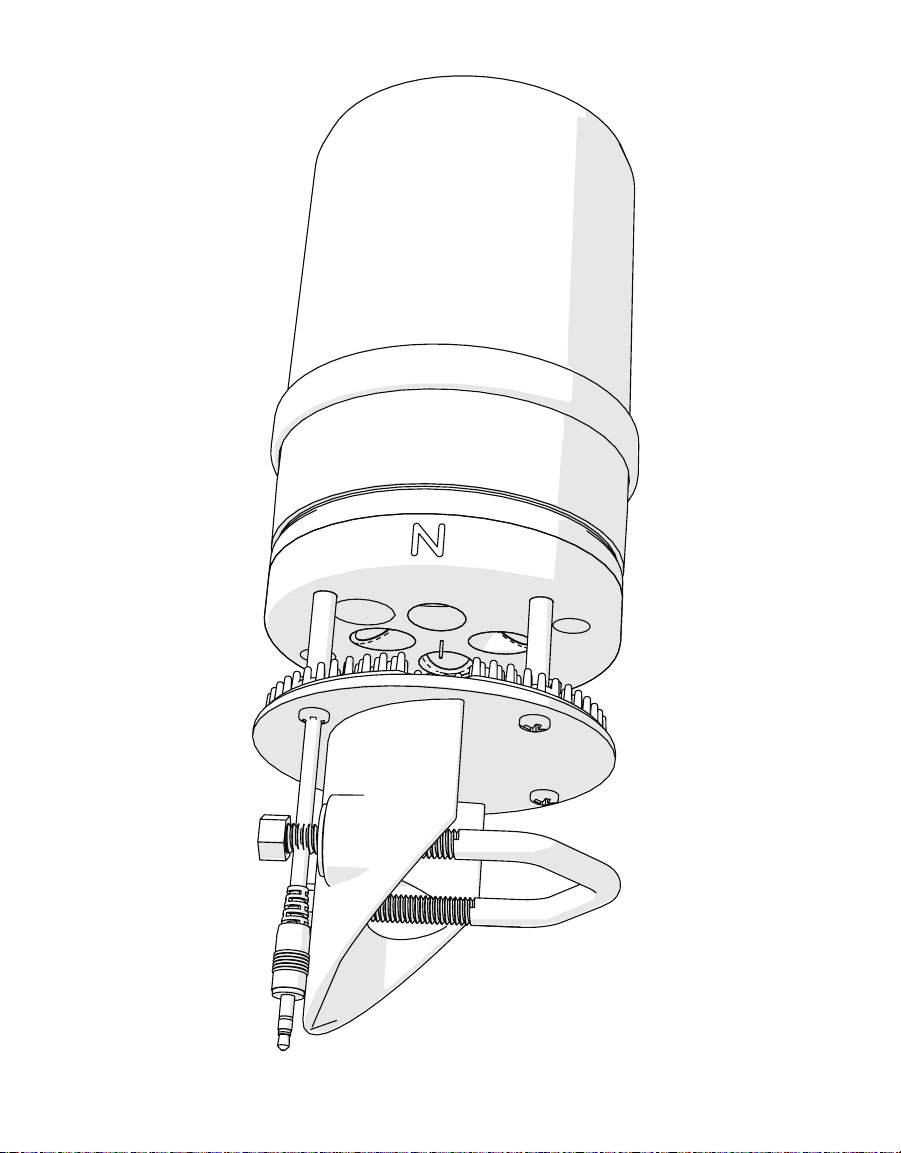
3.3 ANEMOMETER
The space underneath the rain gauge is where the ATMOS41 measures wind speed.
Ultrasonic signals emitted from transducers at right angles to each other bounce off
the porous sintered glass plate (Figure4) and back up to the opposite sensor. The
speed ofsound is affected by the wind, and the wind speed is calculated by measuring
differences in the time it takes for sound to travel back and forth between sensors
(seeSection3.12.1 onpage 19).
Figure4 Anemometer
14
SYSTEM
3.4 VAPOR PRESSURE SENSOR
The vapor pressure sensor (Figure5) on the ATMOS41 is located behind the circular Teflon
™
membrane in the same housing as the sonic transducers. The Teflon protects the sensor
from liquid water and dust while allowing water vapor to freely pass to the sensor and
equilibrate with air vapor pressure. The sensor measures relative humidity and temperature
and computes vapor pressure as the saturation vapor pressure at sensor temperature
multiplied by the relative humidity.
Figure5 Vapor Pressure Sensor
If the relative humidity of the air is desired, it can be computed using Equation 1.
Equation 1
()
RH eT
e
,rair
sair
a
=
where eais the vapor pressure of the air, from the ATMOS41, and es(Tair)is saturation vapor
pressure at the air temperature given by the ATMOS41.
The saturation vapor pressure is calculated using the Magnus-Tetens equation (Equation 2)
with the following coefficients described by Buck (1981).
Equation 2
expeT acT
bT
sair
air
air
=+
eo
Water a= 0.611 kPa b= 17.502 c = 240.97 °C Tair = NA
Ice a= NA b= 21.87 c = 265.5 °C Tair = Temperature in °C
Vapor pressure sensor
Teflon screen
15
ATMOS 41
Unlike relative humidity, vapor pressure does not depend on temperature, and is generally
conservative over time and space. The vapor pressure of the atmosphere near the relative
humidity sensor is the same as the vapor pressure at the relative humidity sensor, even if the
relative humidity sensor is not at the same temperature as the atmosphere. Additionally, it
is the vapor pressure of the atmosphere (not RH) that controls the rate of vapor phase water
transport (e.g., evaporation, transpiration, and distribution of water vapor). Therefore, vapor
pressure is a much more useful measure of atmospheric moisture than relative humidity.
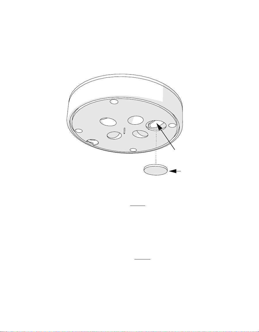
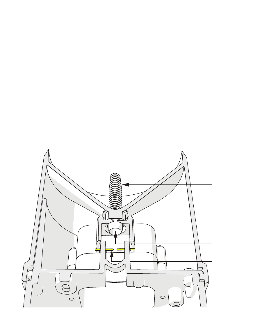
3.5 RAIN GAUGE
The ATMOS41 contains a 9.31 cm diameter rain gauge. During rain events, the flared hole
(Figure6) forms the rain into drops that pass by the drip counter. The spring (Figure6) acts
as a filter to keep out large particles but still allows enough flow so water does not back
up. Gold pins (Figure6) measure each drop of rain. Because the flared hole forms a drop of
a known size, the ATMOS41 counts the drops and calculate the water volume. As the rain
intensity increases, the drops become smaller, but the ATMOS41 firmware contains an
algorithm to automatically compensate for drop size as the rain increases.
IMPORTANT: The ATMOS41 must be within approximately ±2 degrees of dead level in both the X and Y directions to
accurately measure rainfall. If not within this range,drops from the flared hole can miss the gold electrodes entirely.
Figure6 Rain gauge
Spring
Flared hole
Gold
electrodes
16
SYSTEM
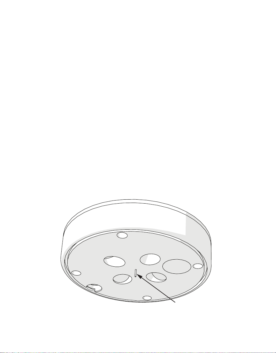
The rain gauge locks in place using two pegs on the side of the rain gauge funnel. Follow the
steps below to get inside the rain gauge.
1. Press down against the spring and turn counter clockwise slightly.
Look for the graphic on the side of the rain gauge.
ATTENTION: BE CAREFUL TO UNPLUG THE PYRANOMETER CONNECTOR INSIDE THE FUNNEL BEFORE FULLY
REMOVING THE FUNNEL.
2. Before replacing the cover, be sure to reattach the pyranometer connector as follows:
a. Insert the white female connector into the black male plug (check plug direction).
b. Check to be sure the downspout screen is in place on the water exit.
This keeps bugs out of the interior of the sensor.
3.6 TEMPERATURE SENSOR
The ATMOS41 temperature measurement (Figure7) is in the center of the anemometer
area where a small stainless steel needle containing a tiny temperature sensor (thermistor)
extends from the middle of the four sonic transducers. Unlike most air temperature
measurements, the weather station sensor is not covered with louvered plates to protect
from solar heating. Instead, it sits in open air, susceptible to solar heating of the instrument
body. However, the ATMOS41 calculates the air temperature accurately because solar
radiation and the wind speed are known. These are the two main parameters that determine
the error between measured air temperature and the actual air temperature. Therefore, it is
possible to solve the energy balance to get what the actual temperature should be based on
the solar load of the body and the convective cooling of that temperature sensor.
Figure7 Temperature sensor
Temperature sensor

17
3.7 LIGHTNING SENSOR
The lightning sensor acts much like an AM radio. During a thunderstorm, the crack of the
lightning disrupts the AM signal. The integrated circuit inside the sensor listens for this
crackle, and when the sensor detects a disturbance, it registers the time of and distance
(intensity of signal) to the strike. The sensor outputs the total number of strikes and average
distance to these strikes in the measurement period. The sensitivity of the lightning sensor
can be adjusted using the ProCheck (see Section3.9 onpage 18).
3.8 COMPASS
The ATMOS41 has an internal digital compass that is used primarily as a diagnostic tool to
determine if the ATMOS41 has been inadvertently rotated after installation. It can also be
used to correct the wind direction measurement, but only if the ATMOS41 is mounted on a
nonferrous mounting pole, as ferrous metal interferes with the digital compass accuracy.
All ATMOS41 units are shipped with the compass-corrected wind direction turned OFF, so
the typical installation requires that the Non the side of the weather station be oriented to
north (true north, not magnetic north) for accurate wind direction measurements.
If the ATMOS41 is mounted on a nonferrous pole, the wind direction compass correction can
be turned ON (see Section3.9 onpage 18) and the ATMOS41 does not need to be oriented
towards north for accurate wind direction measurements.
NOTE: The compass-corrected wind direction will orient to magnetic north, so a correction will have to be applied to
account for magnetic declination.
Even if the compass correction is turned OFF, the compass orientation will still be
included in ATMOS41 output, even if a ferrous metal post is affecting the accuracy of
the measurement. These orientation data are still useful as a diagnostic tool to identify
unintended rotation of the ATMOS41, which would affect the accuracy of the wind
direction measurement.

18
SYSTEM
3.9 CONFIGURING THE COMPASS AND LIGHTNING SENSOR
USING PROCHECK
A ProCheck can be used to configure the ATMOS41 compass and lightning sensor for optimal
performance. To make these modifications, the weather station must be plugged into the
ProCheck via the stereo port.
Figure8 ATMOS41 configuration screen
3.9.1 COMPASS CONFIGURATION
When the compass is set to ON, the onboard compass automatically corrects wind direction.
If the compass is set to OFF, the wind direction is relative to the N(North) indicator on the
side of the weather station. Since the compass is extremely sensitive to magnetic fields,
it may be desirable to recalibrate the compass or even turn the compass correction OFF
depending on the installation location and mounting.
Follow the steps below to turn the compass correction ON or OFF.
1. Highlight the compass setting
2. Press Enter to toggle the setting
Follow the steps below to perform a compass calibration.
1. Turn the compass correction to ON.
2. Highlight the compass calibration option
3. Press Enter to begin the calibration.
4. Follow the directions on the ProCheck screen.
3.9.2 LIGHTNING STRIKE REJECT LEVEL CONFIGURATION
The Strike Reject Lvl adjusts the lightning sensor threshold used to differentiate
between man-made electrical noise and lightning strikes. The higher the value, the less
likely man-made electrical noise will cause a false lightning strike, but the more likely
lightning strike events from far away will be filtered out and missed. A value between
0 to 15 can be used. Generally, a small deviation of one or two from the default value is
sufficient to tune the level to the installation environment.
Other manuals for ATMOS 41
5
Table of contents
Other METER Weather Station manuals


Popular Weather Station manuals by other brands


Chacon
Chacon 54419 user manual

Hama
Hama EWS-390 Operating instruction

Oregon Scientific
Oregon Scientific Weather Home RAR213HGX manual

La Crosse Technology
La Crosse Technology WS-7049-Mah instruction manual

Conrad
Conrad WS 9750-IT operating instructions

Auriol
Auriol 4-LD4868 Usage and safety instructions