METER ATMOS 41 User manual

ATMOS 41

i
TABLE OF CONTENTS
1. Introduction..............................................................................................1
2. Operation ...................................................................................................2
2.1 Installation ................................................................................................2
2.2 Connecting................................................................................................. 3
2.2.1 Connect to METER Logger................................................................4
2.2.2 Connect to Non-METER Logger........................................................5
2.3 Communication .........................................................................................6
3. System.........................................................................................................7
3.1 Specifications............................................................................................7
3.2 Pyranometer ............................................................................................ 12
3.3 Anemometer ............................................................................................ 13
3.4 Vapor Pressure/Relative Humidity Sensor ............................................... 14
3.5 Rain Gauge............................................................................................... 16
3.6 Temperature Sensor................................................................................. 17
3.7 Lightning Sensor...................................................................................... 18
3.8 Barometric Pressure Sensor .................................................................... 19
3.9 Tilt Sensor................................................................................................ 19
3.10 Theory.................................................................................................... 19
3.10.1 Wind Speed and Direction............................................................ 19
3.10.2 Temperature................................................................................. 21
3.11 Limitations............................................................................................. 22
3.11.1 Snow and Ice Accumulation ......................................................... 22
3.11.2 Heavy Rain and Strong Wind ........................................................ 23
3.11.3 Electromagnetic Interference...................................................... 23
18169-04
9.18.2019

ii
3.12 Measurements with METER Loggers...................................................... 23
4. Service....................................................................................................... 25
4.1 Calibration ............................................................................................... 25
4.2 Recalibration Recommendations............................................................. 26
4.3 Cleaning and Maintenance....................................................................... 26
4.4 Update Firmware ..................................................................................... 28
4.5 Troubleshooting....................................................................................... 28
4.6 Customer Support.................................................................................... 30
4.7 Terms and Conditions .............................................................................. 31
References .................................................................................................... 32
Index ................................................................................................................. 33


1
1. INTRODUCTION
Thank you for choosing the ATMOS41 All-in-One Weather Station from METER Group.
The ATMOS41 All-in-One Weather Station is designed for continuous monitoring of
environmental variables, including all standard weather measurements (Section 3).
TheATMOS41 measures the following:
• Solar radiation
• Precipitation
• Air temperature
• Barometric pressure
• Vapor pressure
• Relative humidity
• Wind speed
• Wind direction
• Maximum wind gust
• Lightning strikes
• Lightning distance
• Tilt
All sensors are integrated into a single, small form-factor unit, requiring minimal installation
effort. A robust, no moving parts design that prevents errors because of wear or fouling make
the weather station ideal for long-term, remote installations. ATMOS 41 can be used for a
variety of applications:
• Weather monitoring
• Microenvironment monitoring
• Spatially-distributed environmental monitoring
• Crop weather monitoring
• Fire danger monitoring
• Weather networks
Additional advantages include its low-power design that supports battery-operated data
loggers and the SDI-12 three-wire interface. A tilt sensor warns the user of out-of-level
condition, and no configurations are necessary.
Prior to use, verify all ATMOS 41 system components are included and appear in
goodcondition.

2
OPERATION
2. OPERATION
Please read all instructions before operating the ATMOS41 to ensure it performs to its
full potential.
PRECAUTIONS
METER sensors are built to the highest standards, but misuse, improper protection,
or improper installation may damage the sensor and possibly void the manufacturer’s
warranty. Before integrating ATMOS41 into a system, follow the recommended installation
instructions and have the proper protections in place to safeguard sensors from damage.
2.1 INSTALLATION
Follow the steps listed in Table 1 to set up the ATMOS41 and start collecting data.
Table 1 Installation
Tools Needed
Wrench 13 mm (1/2 in)
Mounting pole 31.8 to 50.8 mm (0.25 to 2.0 in) diameter
NOTE: Smaller mounts are compatible if washers are added to the V-bolt (not included).
United States standard pipe sizes that are compatible are 1.00-, 1.25-, and 1.50-in. Square
tubing with a width of 1.25 to 2.00 in or T-posts can also work as mounting options.
Preparation
Consider the Surroundings
Ensure that site selection is far from wind obstruction.
Make sure surrounding objects will not shade the solar radiation sensor.
Choose a site far from sources of high electromagnetic interference (EMI),
such as high-voltage power transmission lines. EMI sources adversely affect
ATMOS41 lightning and rainfall measurements.
Conduct System Check
Plug the weather station into the logger (Section 2.2).
Verify all sensors are functional and read within expected ranges.
Adjust Pole Height
Prepare the mounting pole to the appropriate height. Many installations
require the ATMOS41 to be mounted 2 m above ground, but mounting height
can be adjusted based on the specific application.
Mounting
Install on Mounting Pole
Use the V-bolt to mount the unit at the desired height. The V-bolt is compatible
with most meterological stands, poles, tripods, and other mounts.
Mount Toward True North
Orient the Nengraved on the side of the instrument should be oriented to point
true north (not magnetic north). The ATMOS41 must be oriented correctly by
hand for accurate wind direction measurements.

3
ATMOS 41
Table 1 Installation (continued)
Mounting
(continued)
Level the System
Use the bubble level underneath the ATMOS41 or a PROCHECK display to level
the weather station. The angle of the mounting pole may need to be adjusted
or shims added to the ATMOS41–pole interface to achieve level. The ATMOS41
must be within approximately ±2° of dead level (0, 0) in both the X and Y
directions to accurately measure rainfall and solar radiation.
Secure the System
Tighten the V-bolt nuts by hand until hand-tight, and then gently tighten with a
wrench, securing the ATMOS 41 flat and tight against the top of the stand.
CAUTION: Do not overtighten V-bolt.
Secure and Protect Cables
NOTE: Improperly protected cables can lead to severed cables or disconnected sensors.
Cabling issues can be caused by many factors such as rodent damage, driving over sensor
cables, tripping over cables, not leaving enough cable slack during installation, or poor
sensor wiring connections.
Install cables in conduit or plastic cladding when near the ground to avoid
rodent damage.
Gather and secure cables between the ATMOS 41 and the data logger to the
mounting mast in one or more places.
Connect to Data Logger
Plug the sensor into a data logger.
Use the data logger to make sure the sensor is reading properly.
Verify these readings are within expected ranges.
For more instructions on connecting to data loggers, refer to Section 2.2.
NOTE: ATMOS41 will not work with legacy Decagon data loggers (Em50 Series and Em5B) because the ATMOS41
outputs contain too many parameters.
2.2 CONNECTING
The ATMOS41 works seamlessly with METER data loggers. This system will not work
with legacy data loggers (Decagon Em5, Em5B, Em50, Em50R, and Em50G) because the
ATMOS41 has too many output parameters (previously limited to three). The ATMOS 41 can
also be used with other data loggers, such as those from Campbell Scientific, Inc. For
extensive directions on how to integrate the sensor into third-party loggers, refer to the
ATMOS41 Integrator Guide (metergroup.com/atmos41-support).
ATMOS41 sensors require an excitation voltage in the range of 3.6 to 15.0 VDC and operates
at a 2.8- to 5.5-VDC level for data communication. The ATMOS41 can be integrated using
SDI-12 protocol. See the ATMOS41 Integrator Guide for details on interfacing with data
acquisition systems.

4
OPERATION
ATMOS41 sensors come with a 3.5-mm stereo plug connector (Figure1) to facilitate easy
connection with METER loggers. ATMOS41 sensors may be ordered with stripped and tinned
wires to facilitate connecting to some third-party loggers (Section 2.2.2).
Ground
Digital communication
Power
Figure1 3.5-mm stereo plug connector wiring
The ATMOS41 comes standard with a 5-m cable. It may be purchased with custom cable
lengths for an additional fee (on a per-meter basis). In some instances, the cable can be
extended beyond 75 m by the user, but this is discouraged for a variety of reasons. Please
contact Customer Support for more details before extending or splicing cables.
2.2.1 CONNECT TO METER LOGGER
The ATMOS41 works most efficiently with ZENTRA series data loggers. Check the
METER downloads webpage (metergroup.com/downloads) for the most recent data
logger firmware. Logger configuration may be done using either ZENTRA Utility (desktop
and mobile application) or ZENTRA Cloud (web-based application for cell-enabled data
loggers).
NOTE: This system will not work with legacy data loggers (Decagon Em5, Em5B, Em50, Em50R, and Em50G).
1. Plug the stereo plug connector into one of the sensor ports on the logger.
2. Use the appropriate software application to configure the chosen logger port for the
ATMOS 41. METER data loggers will automatically recognize ATMOS 41 sensors.
3. Set the measurement interval.
METER data loggers measure the ATMOS 41 every minute and return the average of the
1-min data across the chosen measurement interval.
NOTE: The ATMOS41 draws more current than most other METER sensors because it makes frequent wind
speed and precipitation measurements. As a result, plugging multiple ATMOS41 stations into a single ZENTRA or
EM60 data logger may have significant impact on battery life. At times or in regions with plentiful sunshine, the
solar panel should provide ample charge and this should not be an issue. During the winter or periods of extended
heavy clouds, the solar panel may not provide enough charging current to keep the system running with multiple
ATMOS41 units. METER recommends using only one ATMOS41 per ZENTRA or EM60 data logger.
ATMOS 41 data can be downloaded from METER data loggers using either ZENTRA Utility or
ZENTRA Cloud. Refer to the logger user manual for more information about these programs.
5
ATMOS 41
2.2.2 CONNECT TO NONMETER LOGGER
The ATMOS41 can be purchased for use with non-METER (third party) data loggers. Refer
to the third-party logger manual for details on logger communications, power supply,
and ground ports. The ATMOS41 Integrator Guide also provides detailed instructions on
connecting sensors to non-METER loggers.
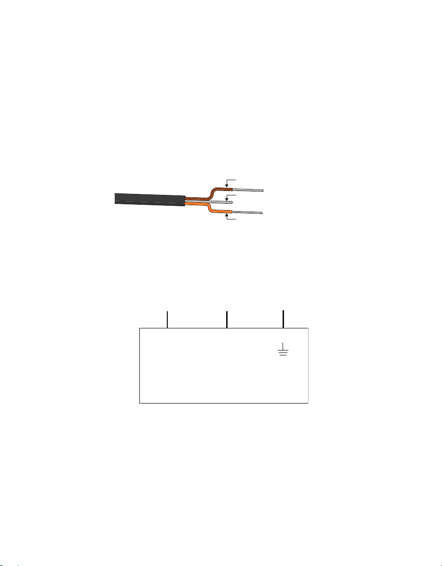
ATMOS 41 sensors can be ordered with stripped and tinned (pigtail) wires for use with screw
terminals. Refer to the third-party logger manual for details on wiring.
Connect the ATMOS41 wires to the data logger as illustrated in Figure2 and Figure3, with
the power supply wire (brown) connected to the excitation, the digital out wire (orange) to a
digital input, and the bare ground wire to ground.
Ground (bare)
Digital
communication (orange)
Power (brown)
Figure2 Pigtail wiring
NOTE: Some early ATMOS41 units may have the older Decagon wiring scheme where the power supply is white,the
digital out is red, and the bare wire is ground.
Excitation Digital
in
Data Logger
Ground
Digital
communication
(orange)
Ground
(bare)
Power
(brown)
Figure3 Wiring diagram
NOTE: The acceptable range of excitation voltages is from 3.6 to 15.0 VDC.To read the ATMOS41 with Campbell
Scientific data loggers,power the sensors off a 12-V port.
If the ATMOS41 cable has a standard stereo plug connector and needs to be connected
to a non-METER data logger, use one of the following two options.
Option 1
1. Clip off the stereo plug connector on the sensor cable.
2. Strip and tin the wires.
3. Wire it directly into the data logger.

6
OPERATION
This option has the advantage of creating a direct connection and minimizes the chance of
the sensor becoming unplugged. However, it then cannot be easily used in the future with a
METER readout unit or data logger.
Option 2
Obtain an adapter cable from METER.
The adapter cable has a connector for the stereo plug connector on one end and three wires
(or pigtail adapter) for connection to a data logger on the other end. The stripped and tinned
adapter cable wires have the same termination as in Figure3: the brown wire is excitation,
the orange is output, and the bare wire is ground.
NOTE: Secure the stereo plug connector to the pigtail adapter connections using adhesive-lined heat shrink to ensure
the sensor does not become disconnected during use.
2.3 COMMUNICATION
The ATMOS 41 communicates using SDI-12 communication protocol. To obtain detailed
instructions, refer to the ATMOS 41 Integrator Guide.
The SDI-12 protocol requires that all sensors have a unique address. ATMOS 41 sensor
factory default is an SDI-12 address of 0. To add more than one SDI-12 sensor to a bus, the
sensor address must be changed as described in these steps.
1. Using a PROCHECK connected to the sensor, press the MENU button to bring up the
Configuration tab.
NOTE: If the PROCHECK does not have this option, please upgrade its firmware to the latest version from the
METER Legacy Handheld Devices webpage.
2. Scroll down to SDI-12 Address. Press ENTER.
3. Press the UP or DOWN arrows until the desired address is highlighted.
Address options include 0...9, A…Z, and a…z.
4. Press ENTER.
Detailed information can also be found in the application note Setting SDI-12 addresses on
METER digital sensors using Campbell Scientific data loggers and LoggerNet (metergroup.
com/environment/articles/setting-addresses-using-campbell-scientific-data-loggers/).
When using the sensor as part of an SDI-12 bus, excite the sensors continuously to avoid
issues with initial sensor startup interfering with the SDI-12 communications.

7
ATMOS 41
3. SYSTEM
This section describes the ATMOS 41 All-in-One Weather Station system.
3.1 SPECIFICATIONS
MEASUREMENT SPECIFICATIONS
Solar Radiation
Range 0–1750 W/m2
Resolution 1 W/m2
Accuracy ±5% of measurement typical
Precipitation
Range 0–400 mm/h
Resolution 0.017 mm
Accuracy ±5% of measurement from 0 to 50 mm/h
Vapor Pressure
Range 0–47 kPa
Resolution 0.01 kPa
Accuracy Varies with temperature and humidity, ±0.2 kPa typical below 40 °C
Figure4 Vapor pressure sensor accuracy
8
SYSTEM
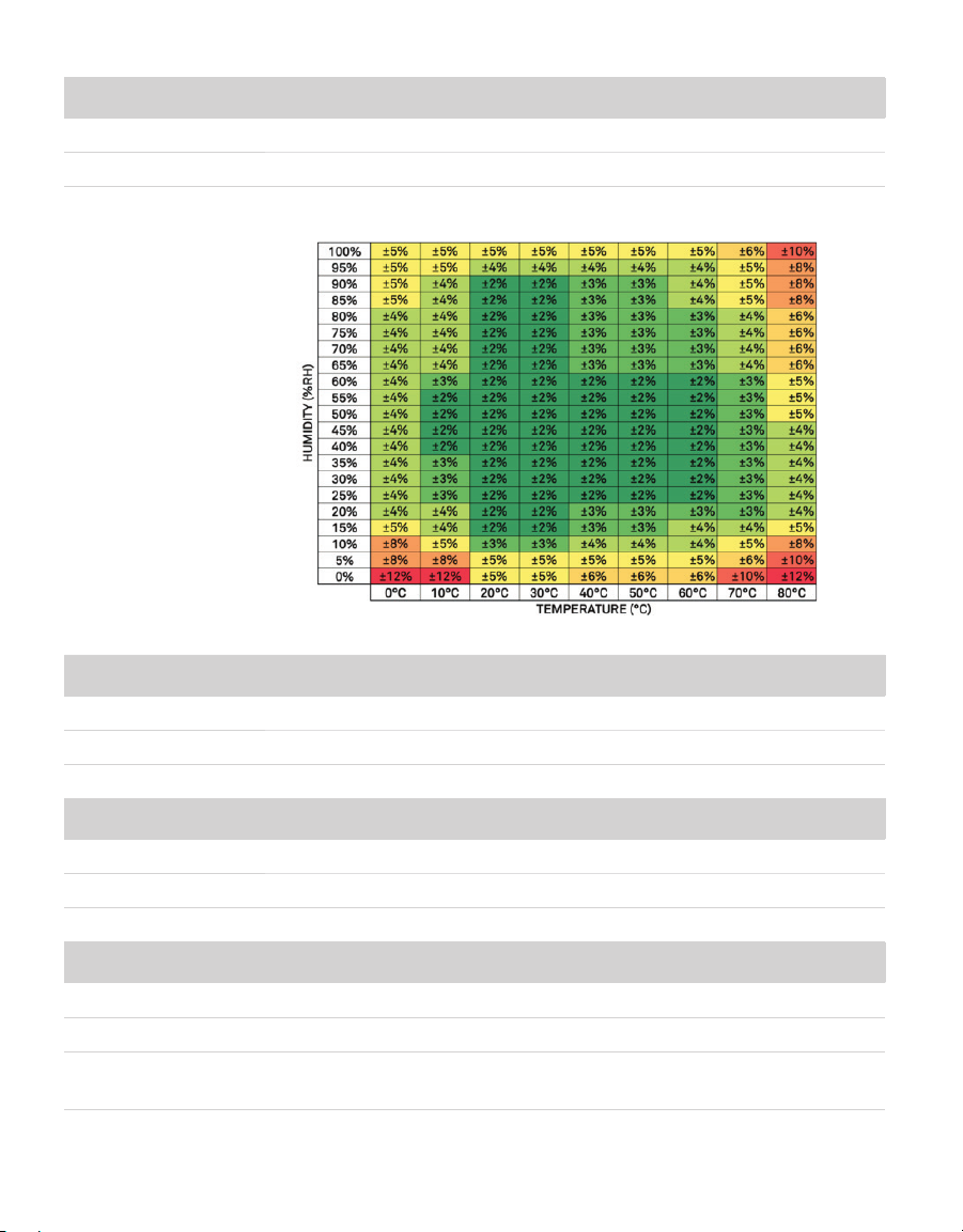
Relative Humidity
Range 0–100% RH
Resolution 0.1% RH
Accuracy Varies with temperature and humidity, ±3% RH typical
Figure5 RH sensor accuracy
Air Temperature
Range –50 to 60 °C
Resolution 0.1 °C
Accuracy ±0.6 °C
Humidity Sensor Temperature
Range –40 to 50 °C
Resolution 0.1 °C
Accuracy ±1.0 °C
Barometric Pressure
Range 50–110 kPa
Resolution 0.01 kPa
Accuracy ±0.1 kPa from –10 to 50 °C
±0.5 kPa from –40 to 60 °C

9
ATMOS 41
Horizontal Wind Speed
Range 0–30 m/s
Resolution 0.01 m/s
Accuracy The greater of 0.3 m/s or 3% of measurement
Wind Gust
Range 0–30 m/s
Resolution 0.01 m/s
Accuracy The greater of 0.3 m/s or 3% of measurement
Wind Direction
Range 0°–359°
Resolution 1°
Accuracy ±5°
Tilt
Range –90° to 90°
Resolution 0.1°
Accuracy ±1°
Lightning Strike
Range 0–65,535 strikes
Resolution 1 strike
Accuracy Variable with distance, >25% detection at <10 km typical
Lightning Average Distance
Range 0–40 km
Resolution 3 km
Accuracy Variable

10
SYSTEM
COMMUNICATION SPECIFICATIONS
Output
SDI-12 communication
Data Logger Compatibility
METER ZL6 and EM60 data loggers or any data aquisition systems capable of switched
3.6- to 15.0-VDC excitation and SDI-12 communication
PHYSICAL CHARACTERISTICS
Dimensions
Diameter 10 cm (3.94 in)
Height 34 cm (13.39 in), includes rain gauge filter
Operating Temperature Range
Minimum –50 °C
Typical NA
Maximum 60 °C
NOTE: Barometric pressure and relative humidity sensors operate accurately at a minimum of –40 °C.
Cable Length
5 m (standard)
75 m (maximum custom cable length for additional cost)
NOTE: Contact Customer Support if a nonstandard cable length is needed.
Connector Types
3.5-mm stereo plug connector or stripped and tinned wires
ELECTRICAL AND TIMING CHARACTERISTICS
Supply Voltage (VCC to GND)
Minimum 3.6 VDC continuous
Typical NA
Maximum 15.0 VDC continuous
NOTE: The ATMOS 41 must be continulously powered to work properly.
NOTE: For the ATMOS 41 to meet digital logic levels specified by SDI-12, it must be excited at 3.9 VDC or greater.

11
ATMOS 41
Digital Input Voltage (logic high)
Minimum 2.8 V
Typical 3.0 V
Maximum 5.5 V
Digital Input Voltage (logic low)
Minimum –0.3 V
Typical 0.0 V
Maximum 0.8 V
Digital Output Voltage (logic high)
Minimum NA
Typical 3.6 V
Maximum NA
NOTE: For the ATMOS 41 to meet digital logic levels specified by SDI-12, it must be excited at 3.9 VDC or greater.
Power Line Slew Rate
Minimum 1.0 V/ms
Typical NA
Maximum NA
Current Drain (during measurement)
Minimum 0.2 mA
Typical 8.0 mA
Maximum 33.0 mA
Current Drain (while asleep)
Minimum 0.2 mA
Typical 0.3 mA
Maximum 0.4 mA
Power Up Time (SDI ready)—aRx! Commands
Minimum NA
Typical 10 s
Maximum NA
12
SYSTEM
Power Up Time (SDI ready)—Other Commands
Minimum NA
Typical 800 ms
Maximum NA
Measurement Duration
Minimum NA
Typical 110 ms
Maximum 3,000 ms
COMPLIANCE
Manufactured under ISO 9001:2015
EM ISO/IEC 17050:2010 (CE Mark)
3.2 PYRANOMETER
Solar radiation is measured by a pyranometer that is integrated into the lip of the rain gauge
funnel at the top of the ATMOS 41. Designed, manufactured, and calibrated by experts at
Apogee Instruments, the miniature pyranometer uses a silicon-cell sensor to measure the
total incoming (direct and diffuse) solar radiation. A carefully developed cosine-correcting
head ensures accurate readings regardless of sun angle, while the painstakingly researched
optical filter material balances cost and performance to ensure the silicon-cell provides
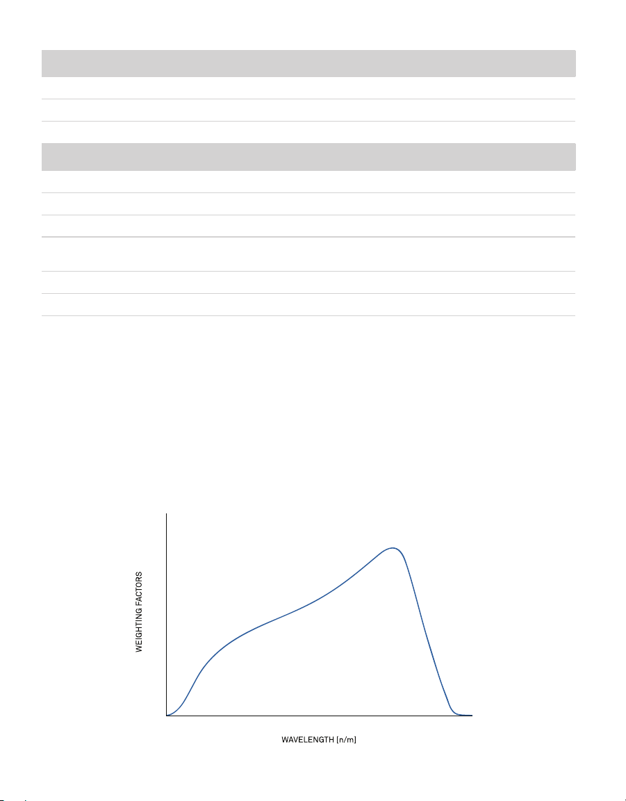
good accuracy regardless of temperature or sensor age. Silicon-cell sensors have excellent
response time to changing radiation conditions and acceptable sensitivity across the solar
spectrum (Figure6), which make them perfect for use on the ATMOS 41.
1.2
1.1
1.0
0.9
0.8
0.7
0.6
0.5
0.4
0.3
0.2
0.1
0.0
300 400 500 600 700 800 900 1000 1100 1200
Figure6 Spectral response estimate of Apogee silicon-cell pyranometers

13
ATMOS 41
Spectral response was estimated by multiplying the spectral response of the photodiode,
diffuser, and adhesive. Spectral response measurements of diffuser and adhesive were
made with a spectrometer, and spectral response data for the photodiode were obtained
from the manufacturer.
Leveling the ATMOS 41 is particularly important for accurate solar radiation measurements.
Out of level, the pyranometer will overestimate some portions of the day while under-
estimating others. Ensure accurate solar radiation measurements by carefully leveling the
ATMOS 41 at installation. Bird droppings and other soiling of the domed sensor surface will
cause serious errors in pyranometer measurements. Check the sensor regularly to make sure
it is clean and check data often to identify possible problems. Isopropyl (rubbing) alcohol and
a Q-tip work well for cleaning the sensor area. Microfiber bags work well, too. Do NOT use an
abrasive cloth on the sensor surface, as it will scratch.
The pyranometer is factory calibrated and the sensor-specific calibration value can be found
on the interior of the rain funnel. This factor has already been added into the ATMOS41 so
there is no need to do anything with it. In the event that this value is needed, it can be found
by taking the funnel off the base and checking underneath. Follow the steps in Section 3.5 to
remove the funnel.
When powered on, the ATMOS41 measures the solar radiation once every 10 s and
records the instantaneous values. When queried, the ATMOS41 outputs the average of the
instantaneous measurements since the last query.
3.3 ANEMOMETER
The space underneath the rain gauge is where the ATMOS41 measures wind speed.
Ultrasonic signals emitted from transducers at right angles to each other bounce off
the porous sintered glass plate (Figure7) and back up to the opposite sensor. The
speed ofsound is affected by the wind, and the wind speed is calculated by measuring
differences in the time it takes for sound to travel back and forth between sensors
(Section3.10.1).
When powered on, the ATMOS41 measures the wind speed and direction once every 10 s and
records the instantaneous wind vector components. When queried, the ATMOS41 outputs
the average of the instantaneous measurements since the last query for wind speed and
direction and the maximum instantaneous wind speed value for wind gust.

14
SYSTEM
Splash
guard
Sintered
glass plate
Figure7 Anemometer
The ATMOS 41 measures wind speed every 10 s and keeps a running average of the last
10 measurements. If an instantaneous measurement is more than eight times the running
average, the instantaneous measurement is rejected. It is not reported as the maximum gust
or included in the data that are averaged over the output interval.
For normal ATMOS 41 use cases, this is an effective method for eliminating inaccuracy
resulting from spurious spikes in wind speed (e.g., bumblebee checking out the ultrasonic
path). In special use cases where data are output frequently and large step changes in wind
speed are present (e.g., turning on a wind tunnel), this spike rejection algorithm may result in
an error code being output.
3.4 VAPOR PRESSURE/RELATIVE HUMIDITY SENSOR
The vapor pressure sensor (Figure8) on the ATMOS41 is located behind the circular Teflon
®
screen in the same housing as the sonic transducers. The Teflon screen protects the sensor
from liquid water and dust while allowing water vapor to freely pass to the sensor and
equilibrate with air vapor pressure. The sensor measures relative humidity and temperature
in addition to computing vapor pressure.

15
ATMOS 41
Teon screen
Vapor pressure sensor
Figure8 Vapor pressure sensor
If the relative humidity of the air is desired, it can be computed using Equation 1.
Equation 1
RHr ,air =
e
a
e
s
( T
air
)
where eais the vapor pressure of the air, from the ATMOS41, and es(Tair ) is saturation vapor
pressure at the air temperature given by the ATMOS41.
The saturation vapor pressure is calculated using the Magnus-Tetens equation (Equation 2)
with the following coefficients described by Buck (1981).
Equation 2
esTair =a exp bTair
c+T
air
⎛
⎝
⎜
⎜
⎜
⎜
⎞
⎠
⎟
⎟
⎟
⎟
⎟
Water a= 0.611 kPa b= 17.502 c
=
240.97 °C Tair
= Temperature in °C
Ice a= 0.611 kPa b= 21.87 c
=
265.5 °C Tair
= Temperature in °C
Unlike relative humidity, vapor pressure does not depend on temperature, and is generally
conservative over time and space. The vapor pressure of the atmosphere near the relative
humidity sensor is the same as the vapor pressure at the relative humidity sensor, even if the
relative humidity sensor is not at the same temperature as the atmosphere. Additionally, it
is the vapor pressure of the atmosphere (not RH) that controls the rate of vapor phase water
transport (e.g., evaporation, transpiration, and distribution of water vapor). Therefore, vapor
pressure is a much more useful measure of atmospheric moisture than relative humidity.
The METER ZENTRA system calculates and outputs vapor pressure deficit (VPD) in the
standard data stream. VPD is simply es(Tair ) – eaand gives a good indication of evaporative
demand.
When powered on, the ATMOS41 measures the vapor pressure once every 60 s and
records the instantaneous values. When queried, the ATMOS41 outputs the average of the
instantaneous measurements since the last query.

16
SYSTEM
3.5 RAIN GAUGE
The ATMOS41 contains a 9.31-cm diameter rain gauge. During rain events, the flared hole
(Figure9) forms the rain into drops that pass by the drip counter. The spring (Figure9) acts
as a filter to keep out large particles but still allows enough flow so water does not back
up. Gold pins (Figure9) measure each drop of rain. Because the flared hole forms a drop of
a known size, the ATMOS41 counts the drops and calculate the water volume. As the rain
intensity increases, the drops become smaller, but the ATMOS41 firmware contains an
algorithm to automatically compensate for drop size as the rain increases.
When powered on, the ATMOS41 counts water drops continuously and adds each drop to an
accumulated total. When queried, the ATMOS41 outputs the total rainfall (in millimeters)
that has accumulated since the last query. Precipitation maximum intensity calculation is
capped at 280 mm/h, available from METER data loggers and software.
IMPORTANT: The ATMOS41 must be within approximately ±2 degrees of dead level (0, 0) in both the X and Y directions
to accurately measure rainfall. If not within this range, drops from the flared hole can miss the gold electrodes entirely.
Spring
Flared hole
Gold electrodes
Figure9 Rain gauge
The rain gauge locks in place using two pegs on the side of the rain gauge funnel. Follow the
steps below to get inside the rain gauge.
1. Line up the lock/unlock graphic located on the side of the rain gauge funnel with the
notch on the interface plate.
2. Press the rain gauge funnel down against the spring and turn counter clockwise until it
clicks in place.
ATTENTION: UNPLUG THE PYRANOMETER CONNECTOR INSIDE THE FUNNEL BEFORE FULLY REMOVING THE
FUNNEL.
Other manuals for ATMOS 41
5
Table of contents
Other METER Weather Station manuals


