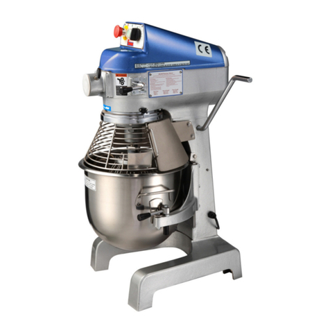
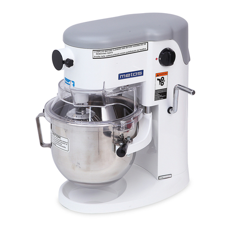
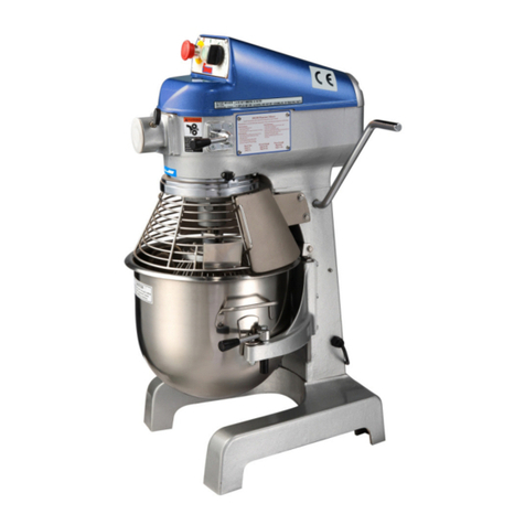
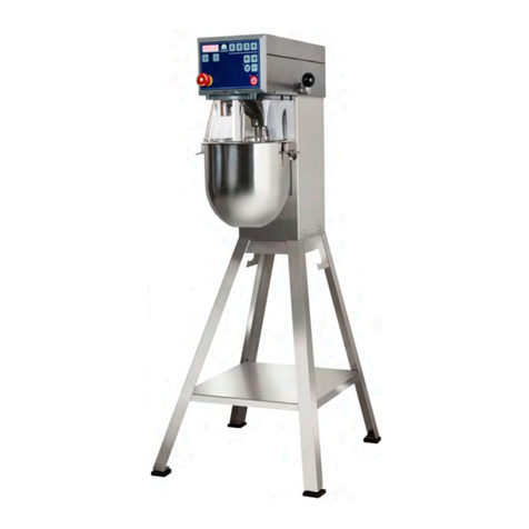
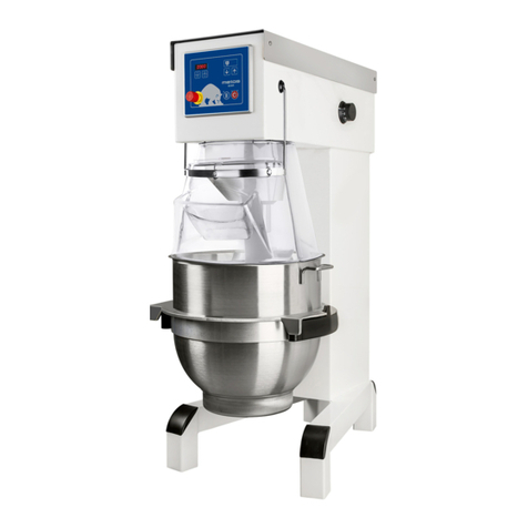
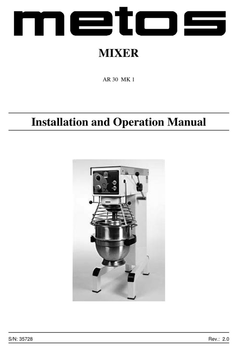
Metos AE40 Series User manual

MIXER
VL3
TYPE: AE40
Installation and Operation Manual
S/N: Rev.: 2.0


17.3.2005 Rev. 2.0
1
Dear Customer,
Congratulations on deciding to choose a Metos appliance for your kitchen activities. You
made an excellent choice. We will do our best to make you a satisfied Metos customer
like thousands of customers we have around the world.
Please read this manual carefully. You will learn correct, safe and efficient working meth-
ods in order to get the best possible benefit from the appliance. The instructions and hints
in this manual will give you a quick and easy start, and you will soon note how nice it is
to use the Metos equipment.
All rights are reserved for technical changes.
You willfind the main technical dataon therating plate fixed to the equipment. When you
need service or technical help, please let us know the serial number shown on the rating
plate. This will make it easier to provide you with correct service.
For your convenience, space is provided below for youto record your local Metos service
contact information.
METOS TEAM
Metos service phone number:...............................................................................................
Contact person:....................................................................................................................

17.3.2005 Rev. 2.0
2

17.3.2005 Rev.
1
1. General ......................................................................................................... 1
1.1 Symbols used in the manual .......................................................................................... 1
1.2 Symbols used on the appliance ...................................................................................... 1
1.3 Checking the relationship of the appliance and the manual .......................................... 1
2. Safety .............................................................................................................. 3
2.1 Safety instructions in case of malfunction ..................................................................... 3
2.2 Disposal of the appliance ............................................................................................... 3
3. Functional description .................................................................................. 4
3.1 Operating principle ........................................................................................................ 4
3.1.1 Operating switches and indicator lights ................................................................. 4
4. Operation instructions ............................................................................... 10
4.1 Operation of the mixer ................................................................................................. 10
4.1.1 Before starting the mixer ..................................................................................... 10
4.1.2 Starting the mixer ................................................................................................. 11
4.1.3 Four fixed speeds ................................................................................................. 11
4.1.4 Indication of operation time ................................................................................. 11
4.1.5 Automatic lowering of bowl ................................................................................ 11
4.1.6 Inspection of the ingredients during operation .................................................... 11
4.1.7 Lowering of bowl ................................................................................................. 12
4.1.8 “JOG” function .................................................................................................... 12
4.1.9 Overload ............................................................................................................... 12
4.1.10 Procedure in case of overload ............................................................................ 12
4.1.11 Changing of fixed speeds ................................................................................... 12
4.1.12 Inductive sensor ................................................................................................. 13
4.1.13 Recommended maximum speeds ....................................................................... 13
4.1.14 The maximum capacity of the mixer ................................................................ 14
4.1.15 Correct use of tools ............................................................................................ 14
4.2 After use ................................................................................................................ 14
4.2.1 Cleaning .............................................................................................................. 14
4.2.2 Maintenance and lubrication ................................................................................ 15
4.2.3 Grease types ......................................................................................................... 16
5. Installation ................................................................................................... 17
5.1 Preparing the installation ............................................................................................. 17
5.2 Installation ................................................................................................................... 17
5.3 Electrical connections .................................................................................................. 17
6. Adjustment instructions ............................................................................. 18

17.3.2005 Rev.
2
6.1 Adjustment of special V-belt ....................................................................................... 18

6.2 Adjustment of bowl centring ....................................................................................... 19
6.3 Adjustment of bowl fixing ........................................................................................... 20
6.4 Adjustment of bowl height .......................................................................................... 20
6.5 Adjustments of speed (low and high speed cam disks) ............................................... 22
6.6 Exchange of control panel ........................................................................................... 23
6.7 Exchange of emergency stop in control panel ............................................................. 25
6.8 Calibration of control panel ......................................................................................... 26
7. Troubleshooting .......................................................................................... 27
9. Technical specifications .............................................................................. 33

17.3.2005 Rev. 2.0
General
1
1. General
Carefully read the instructions in this manual as they contain important information re-
garding proper, efficient and safe installation, use and maintenance of the appliance.
Keep this manual in a safe place for eventual use by other operators of the appliance.
The installation of this appliance must be carried out in accordance with the manufactur-
er’s instructions and following local regulations. The connection of the appliance to the
electric and water supply must be carried out by qualified persons only.
Persons using this appliance should be specifically trained in its operation.
Switch off the appliance in case of failure or malfunction. The periodical function checks
requested in the manual must be carried out according to the instructions. Have the appli-
ance serviced by a technically qualified person authorized by the manufacturer and using
original spare parts.
Not complying with the above may put the safety of the appliance in danger.
The manufacturer does not take responsibility for any damages in case the operation in-
structions and warnings contained in this manual are neglected.
1.1 Symbols used in the manual
This symbol informs about a situation where a safety risk might be at hand.Given instruc-
tions are mandatory in order to prevent injury.
This symbol informs about the right way to perform in order to prevent bad results, appli-
ance damage or hazardous situations.
This symbol informs about recommendations and hints that help to get the best perform-
ance out of the appliance.
1.2 Symbols used on the appliance
This symbol on a part informs about electrical terminals behind the part. The removal of
the part must be carried out by qualified persons only.
1.3 Checking the relationship of the appliance and the manual
The rating plate of the appliance indicates the serial number of the appliance. If the man-
uals are missing, it is possible to order new ones from the manufacturer or the local rep-

17.3.2005 Rev. 2.0
General
2
resentative. When ordering new manuals it is essential to quote the serial number shown
on the rating plate.

17.3.2005 Rev. 2.0
Safety
3
2. Safety
The mixer MUST be bolted to the floor before taken into use.
The mixer is designed for manufacture of products which do not during processing cause
reactions or emit substances which may be detrimental to the user.
In all cases where the parts of the mixer are moving and the safety guard is not closed, it
takes two hands to operate the mixer.
Putting your fingers in the bowl while the mixer is running may cause injuries.
2.1 Safety instructions in case of malfunction
Before any service operations the appliance must be disconnected from the electric net-
work.
2.2 Disposal of the appliance
Once the appliance has reached the end of its useful life, it must be disposed of in com-
pliance with local rules and regulations. The appliance may contain substances/materials
which potentially have an adverse impact on the environment as well as recyclable mate-
rials. The best way of dealing with such substances is to dispose of them through a proper
waste company.

17.3.2005 Rev. 2.0
Functional description
4
3. Functional description
3.1 Operating principle
3.1.1 Operating switches and indicator lights
If the field “Start/Stop” is activated while the mixer is running, the chosen operation time
is reset and the speed is set to minimum. (The same when pushing emergency stop).
The operation time and speed can be changed while the mixer is running.
The operation time can be set to 60 min. and 30 sec. as maximum.
(PHUJHQF\VWRS
%RZOXS
%RZOGRZQ
3DXVH
7LPHXS
7H[WILHOG
7LPHGRZQ
)L[HGVSHHGV
6SHHGLQGLFDWRU
6SHHGGRZQ
6SHHGXS
6WDUW6WRS

17.3.2005 Rev. 2.0
Functional description
5
There is no power connection to the mixer or the emergency stop has been activated -
there is no light on the display (Pos.1).
There is a power connection to the mixer and the bowl is not in its top position. The bowl
can be raised by activating the fields “time down”, “time up” and “bowl up simultaneous-
ly - diodes in the fields are flashing! (Pos.2)
The mixer cannot be started until after the bowl has been raised to its top position.
The bowl can be lowered by activating the field “bowl down”.
3RV
3RV

17.3.2005 Rev. 2.0
Functional description
6
The bowl is in its top position and the mixer is ready for operation by activation of the
field “Start/Stop”.
Speed can be chosen. Operation time can be chosen by activating the fields “time down”,
“time up”
The bowl can be lowered by activating the field “bowl down”.
The mixer is ready for operation by activating the field “Start/Stop”.
The bowl can be lowered by activating the field “bowl down”.
One of the four fixed speeds is chosen by a short activation of the field “2” - five diodes
on the speed scale are flashing.
3RV
3RV

17.3.2005 Rev. 2.0
Functional description
7
The mixer is ready to run by activating the field “Start/Stop”.
The bowl can be lowered by activating the field “bowl down”.
Speed “2” is chosen.
An operation time has been chosen by activating the field “time up” - green diode in the
field “Start/Stop” is flashing.
The mixer is running - green diode in the field “Start/Stop” is constantly alight when the
chosen sped has been reached. The operation time can be changed by activating thefields
“time down” and “time up”.
The mixer can be stopped by activating the field “Start/Stop”.
By activating the field “bowl down” thebowlis automatically lowered when the operation
time has run out.
3RV
3RV

17.3.2005 Rev. 2.0
Functional description
8
The safety guard has been opened while the mixer was running.
When the safety guard is closed, the control panel shows Pos.2.
The emergency stop has just been released. All settings are reset.
The control panel goes back to Pos.2.
3RV
3RV

17.3.2005 Rev. 2.0
Functional description
9
The field “pause” has been activated and the mixer is ready.
The time can be changed by activating the fields “time down” or “time up”.
the bowl can be lowered by activating the field “bowl down”.
The mixer can be started by activating the field “Start/Stop”.
The mixer runs and operation time has been indicated.
Automatic lowering of bowl at ended operation time has been chosen - see Pos.6.
When activating thefield “time down”, automatic lowering of bowl is activated - this does
not happen by activating the field “time up”.
3RV
3RV

17.3.2005 Rev. 2.0
Operation instructions
10
4. Operation instructions
4.1 Operation of the mixer
4.1.1 Before starting the mixer
Mount the required tool in bayonet shaft. Place the bowl in the bowl arms and close the
safety guard.
To raise the bowl, activate the fields “bowl up”, time down” and “time up” simultaneous-
ly, the activation to be continued until the bowl has reached its top position. When the
bowl is approx. 10 cm from its top position, the tool will start to rotate in low speed. The
rotation of the tool and the bowl will stop automatically when the bowl is in its top posi-
tion.
The red diode in “Start/Stop” field is now alight to show that the mixer is ready.
(PHUJHQF\VWRS
%RZOXS
6WDUW6WRS
%RZOGRZQ
3DXVH
7LPHXS
7H[WILHOG
7LPHGRZQ
)L[HGVSHHGV
6SHHGLQGLFDWRU
6SHHGGRZQ
6SHHGXS

17.3.2005 Rev. 2.0
Operation instructions
11
4.1.2 Starting the mixer
Activate the field “Start/Stop” to start the mixer.
Activate the field “speed up” to increase the speed.
Activate the field “speed down” to reduce the speed.
The speed indicator below the fields “1” to “4” shows the mixing speed of the tool.
4.1.3 Four fixed speeds
For quick choice of speed, use the fields “1” to “4”.
Field “1” corresponds to the lowest speed.
Field “2” corresponds approx. to 30% of maximum speed.
Field “3” corresponds approx. to 60% of maximum speed.
Field “4” corresponds to maximum speed.
If it is possible to change the fixed speeds - see the paragraph “Change of fixed speeds”.
4.1.4 Indication of operation time
Before starting the mixer, an operation time for the mixer can be chosen by adjusting the
time on “time down” and “time up”. If the field is activated for longer time, the speed is
increased/reduced quicker.
Minutes and seconds are shown in the text field between “time down” and “time up”.
4.1.5 Automatic lowering of bowl
When an operation time has been indicated and the mixer has been started, it is possible
by activating the field “bowl down” to lower the bowl automatically when the operation
time has run out. the diode in the field is flashing after the activation.
4.1.6 Inspection of the ingredients during operation
If it is wished to stop the mixer without reducing operation time and speed, the field
“pause” can be activated. the mixer will reduce speed and then stop, the operation time
will also stop.
It is now possible to open the safety guard to check the ingredients.
Close the safety guard and activate the field “Start/Stop”, and the mixer will start and will
increase the speed to the speed chosen before “pause” was activated. The operation time
will continue when the mixer has reached the chosen speed.

17.3.2005 Rev. 2.0
Operation instructions
12
4.1.7 Lowering of bowl
When the ingredients in the bowl have been mixed, the mixer is stopped by activating the
field “bowl down”. When the bowl has reached its bottom position, the safety guard can
be opened.
4.1.8 “JOG” function
The mixer is provided with a “JOG” function. Before the bowl reaches its top position,
the tool starts rotating to dig its way into ingredients. For safety reasons the “JOG” func-
tion means that two hands must be used to operate the mixer.
4.1.9 Overload
Do not overload the mixer. Sticky and heavy dough may reduce the capacity of the bowl
by 75%. The capacity is further reduced if the speed of the mixing tool is increased be-
yond the recommended values or if a wrong mixing tool is used. large lumps of fat or
cooled ingredients must be cut into small parts before they are placed in the bowl.
Prolonged overload will make the mixer’s motor protection disconnect the mixer. Leave
the mixer for approx. 3 minutes and restart it again as described under “Procedure in case
of overload”.
4.1.10 Procedure in case of overload
• Push emergency stop
• Open the safety guard
• Empty the bowl
• Close the safety guard and release the emergency stop
4.1.11 Changing of fixed speeds
For the fields “2” and “3” it is possible to change the speed for future mixing jobs. Acti-
vate the field “speed down” or “speed up” to adjust the speed down or up. If required to
store the adjusted speed, activate the field “2” or “3” for a minimum of 5 seconds until the
diode in the speed indicator is flashing.
The adjusted speed has now been stored in the memory.

17.3.2005 Rev. 2.0
Operation instructions
13
4.1.12 Inductive sensor
At the back of the right bowl arm is an inductive sensor (Fig.1) which is activated when
the bowl is placedcorrectly in the bowl arms (all the way back in the bowl arms). the mix-
er can only be operated when the sensor is activated.
It is possible to lift the bowl arms even if the bowl is not mounted.
The bowl arms can move a little in case of maximum loading (mixing of dough), this is
intentional from the designer.
4.1.13 Recommended maximum speeds
&IG
&IG

17.3.2005 Rev. 2.0
Operation instructions
14
4.1.14 The maximum capacity of the mixer
4.1.15 Correct use of tools
Whips should not struck against hard objects as e.g. the edge of the bowl. This will make
the life of the tool shorter due to increasing deformity.
For production of mashed potatoes the special wing whip should be used, not the standard
whip.
4.2 After use
4.2.1 Cleaning
The mixer should be cleaned daily or after use.The mixer should be cleaned with a soft
cloth and clean water. Sulphonated soaps should be used with caution as they destroy the
mixers lubricants.
Never use high pressure cleaning for the mixer.
Bowls and tools of aluminium must not be washed with strong alkaline detergents (pH not
bigger than 9.0)
Whip Beater Hook
Cream Cake dough Bread dough
Egg whites Butter cream Dark bread and the like
Mayonnaise and the like Waffle dough
Minced meat and the like
$5 $EVRUSWLRQ5DWLR$5
([DPSOH$EDVLFUHFLSHFRQWDLQVNJRIVROLGVDQGNJRI
OLTXLG
7KLVJLYHV$5 NJV[
NJV
,IIRULQVWDQFHLWLVUHTXLUHGWRXVHWKHPD[LPXPFDSDFLW\RI
WKHPL[HUWKHFDOFXODWHG$5 LVXVHGIRUGHWHUPLQLQJ
WKHDPRXQWRIVROLGVDQGOLTXLGLQWKHGRXJK
,ID/PL[HULVXVHGDQGDGRXJKZLWK$5 LVWREH
NQHDGHGWKHPD[LPXPFDSDFLW\LV NJV1RZWKHZHLJKWRI
VROLGVLQWKLVGRXJKLVFDOFXODWHG
6ROLGV 0D[ FDSDFLW\ [ NJV [ NJV
$5
:HLJKWRIOLTXLG NJVNJV NJV
/LTXLGLQRIVROLGV
$(
(JJZKLWH
/ HJJV /
:KLSSHGFUHDP /
2WKHU 0D\RQQDLVH
/RLO /
SURGXFWV 0DVKHGSRWDWRHV NJV
%LVFXLWERWWRP
'RXJK/OLTXLG /
6SRQJHFDNH NJV
$(
'RXJKZLWK $5 NJV
D J LY H Q$5 $5 NJV
$5 $5 NJV
This manual suits for next models
1
Table of contents
Other Metos Mixer manuals

Metos
Metos Teddy 5L User manual

Metos
Metos RN 20 User manual

Metos
Metos HMD200 User manual

Metos
Metos SP-100A User manual

Metos
Metos KODIAK CR30 User manual

Metos
Metos SP-502A-B User manual

Metos
Metos AR30 User manual

Metos
Metos Kodiak 30 VL-1C User manual

Metos
Metos AR80 User manual

Metos
Metos SP-30HA-Y User manual