12/32 Gas Ranges (30361-00)
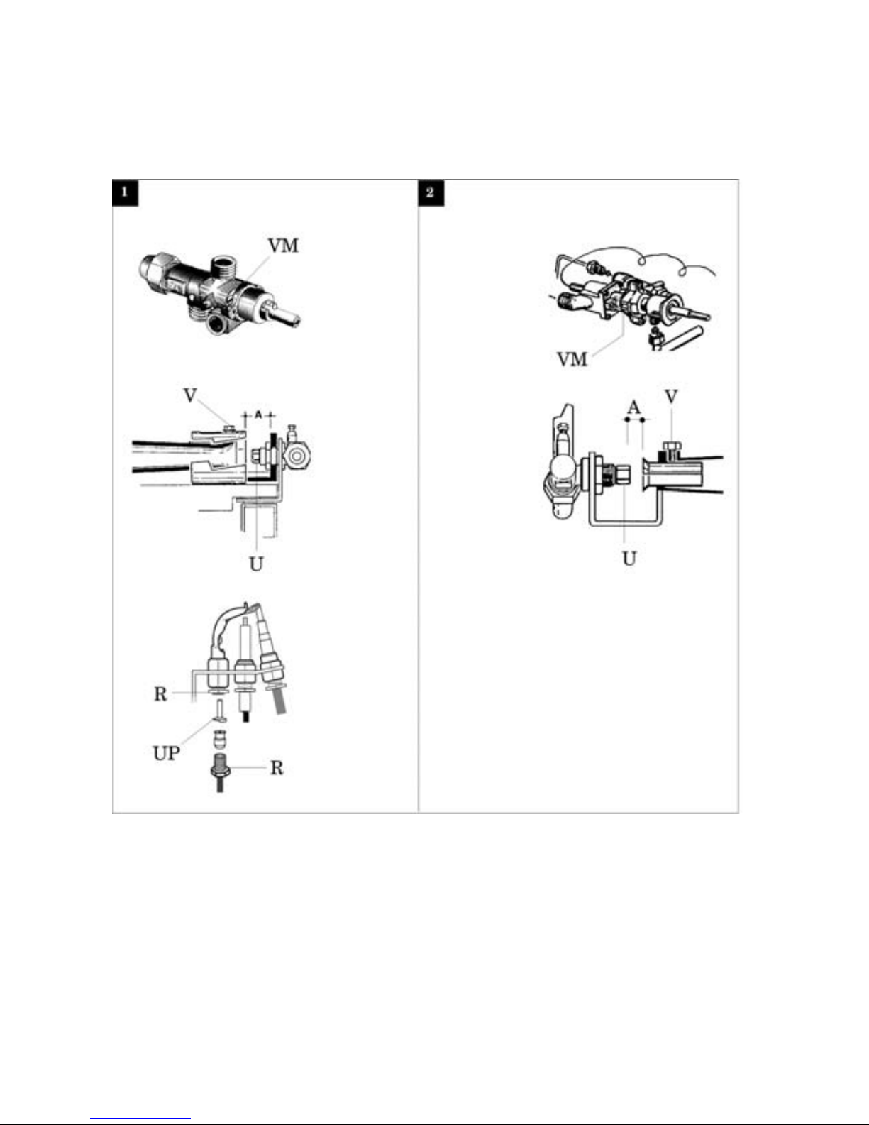
and cooking hob control panel
– Remove the oven floor
– Unscrew nozzle U and change it with the proper
one according to Table T1.
– LoosefixingscrewVand operating on the shutter
adjust primary air inlet at the distance “A”
indicated on Table T1.
– Screw down fixing screw V and seal it with red
paint.
Replacement of gas cock minimum adjustment
screw (Fig. 1 - 2 )
– Remove control panel of appliance.
–For natural and liquid gases
Unscrew the minimum screw VM and replace it
with the proper one indicated in table T1.
–For town gas only
Completely unscrew the minimum screw VM.
Replacement of pilot burner nozzle (Fig. 1 - 2)
– Remove the grates, drip tray, burners, trays
and cooking hob control panel
– Unscrew pipe fitting R and replace nozzle UP
with the proper one indicated in Table T1.
– Screw down pipe fitting R.
Replacement of gas preset adhesive label
– Applythe correctadhesive label which indicates
the new type of gas for which the appliance is
now set.
START-UP
Function check
– Start-upthe applianceaccording toinstructions
for use and check the regularity of the burner
ignition, the absence of gas leaks and the
efficiency of the burnt gas exhaust system as
well as of the ventilation system.
– If necessary consult paragraph “Analysis of
several failures”.
Nominal heat input check
– After installation or adjustment to another type
of gas and at each maintenance intervention
check the heat input of the appliance.
– The nominal heat input is stated in the
“Technical data” table.
– The appliance operates at the nominal heat
input when the nozzles assembled are suitable
for the type of gas used, the inlet pressure is the
one indicated in Table T1 and the electrical
power is the one stated in Table T7.
– For the measurement of the inlet pressure read
paragrah “Inlet pressure check”.
Inlet pressure check
– For the measurement of the inlet pressure use
a gauge having a minimum definition of
0.2 mbar.
– Remove control panel of appliance, remove seal
screw from upstream pressure tapping and
INSTALLATION INSTRUCTIONS
WARNINGS
Installation, adjustments and maintenance of the
appliances must be done by authorized installers,
in accordance with the safety standards in force.
The manufacturer declines any responsibility
if such obligation is not observed.
INSTALLATION
Positioning
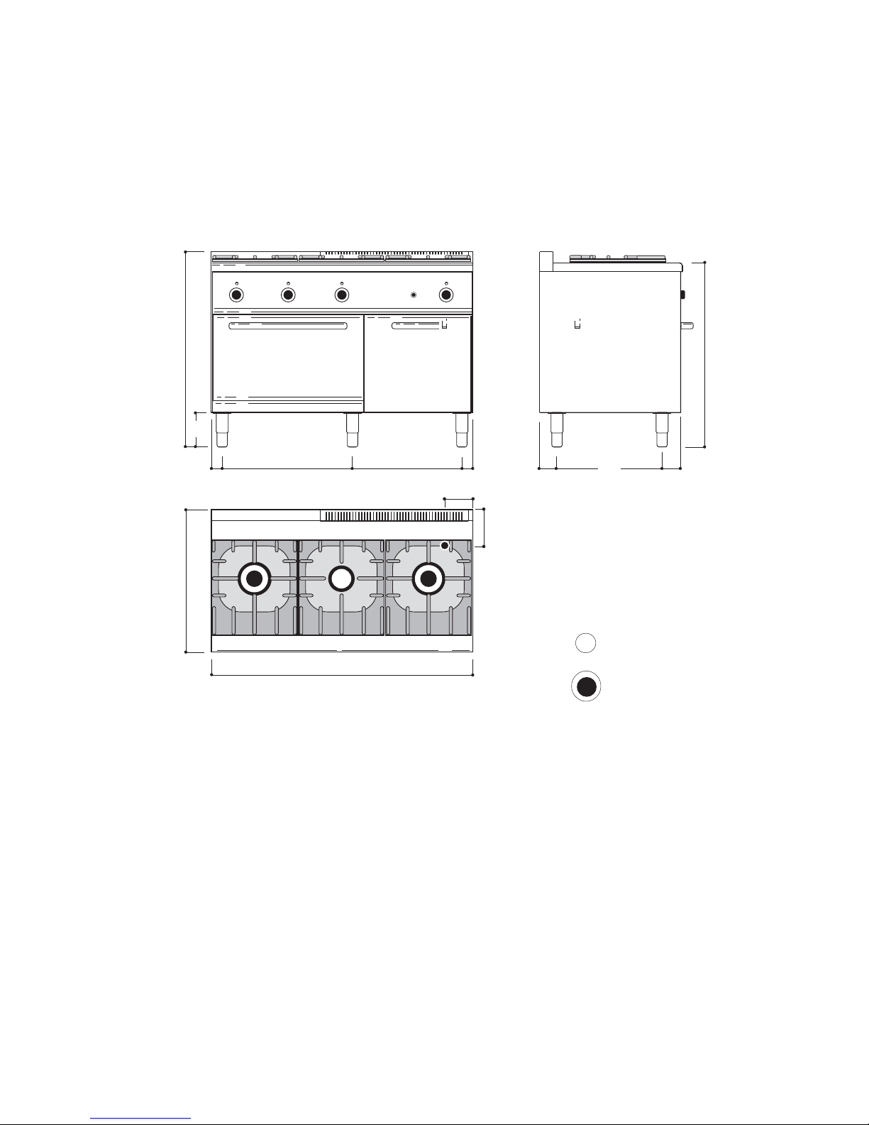
– The overall/connection dimensions and the
technical data are stated in the pages in the
appendix.
– Install the appliances only in sufficiently aired
rooms.
– The appliances are type “A” and for this reason
the rooms must be ventilated in accordance
with the technical standards in force.
– Position appliances at least 10 cm from the
nearby walls. Such distance can be less when
the walls are incombustible or protected by a
thermal insulator.
– The appliances are not suitable for built-in
installation.
Assembly
– Remove the film which protects the external
panels. Any glue remaining on these is to be
removed with a suitable solvent.
– Level appliance by means of the adjustable feet.
– Assemble the stack extension (if foreseen) by
following the instructions enclosed with the
extension itself.
In line union of the appliances
– Put the appliances next to eachother and level
them at the same height.
– Unite the appliances using the special union
joint-coverings supplied upon request.
Connection to the gas piping
– Before carrying out the connection consult the
gas delivery body.
– Install a fast-closing cut-off cock upstream from
the appliance in an easily accessible place.
– Check for any leaks in the connection points.
– Check if the appliance is set for the type of gas
with which it will be fed. If it is not, read
paragraph “Adaptation to another type of gas”.
CONVERSION TO ANOTHER TYPE OF GAS
To adapt appliances to work with other types of gas
carry out all the operations stated below.
Nozzles, minimum adjustment screws and adhesive
labels are in the bag supplied with the appliance.
Replacement of nozzle and burner primary air
adjustment (Fig. 1 - 2 )
– Remove the grates, drip tray, burners, trays