Metra Electronics BT-HD01 User manual

METRA. The World’s best kits.™metraonline.com © COPYRIGHT 2004-2016 METRA ELECTRONICS CORPORATION
REV. 2/9/2016 INSTBT-HD01
Installation instructions for part BT-HD01
CAUTION!
All accessories and switches must be connected before
cycling the ignition. Also, do not remove the factory radio with the key
in the on position, or while the vehicle is running.
• Adds Bluetooth audio streaming to the factory radio
• Can be operated with the handlebar controls
• Will play/pause with ignition on/off
• Will show up on the factory radio as HDBT
• BT-HD01 interface • BT-HD01 harness • 4’ Waterproof USB cable
FEATURES
INTERFACE COMPONENTS
• Wire cutter • Crimp tool • Solder gun • Tape • Torx driver
• Connectors (example: butt-connectors, bell caps, etc.)
TOOLS REQUIRED
BT-HD01
Harley Davidson
Bluetooth Audio
Streaming Interface 2006-2013
Table of Contents
Pre-Installation.......................................................2
Fairing Disassembly ........................................... 3-4
Connections to be made.........................................5
Installing the BT-HD01............................................6
Pairing the BT-HD01 ...............................................6
Operation.................................................................6
APPLICATIONS
HARLEY DAVIDSON (with Advanced Radio)
Electra Glide 2006-2013
Street Glide 2006-2013
Road Glide 2006-2013

BT-HD01
2
Pre-Installation
• Turn the radio on and activate the FM source.
• Turn the ignition key switch to the off position.
• Press and hold any (2) soft buttons on the radio, and then turn the ignition key switch to the on position. The soft buttons are the numbered buttons on the radio.
• Continue holding the (2) soft buttons until “Diag Test” is displayed on the radio screen, and then let go.
• Press the soft key button “4” labeled “Software” on the radio screen.
• The radio screen will then show the current software version. If you do not have V8.250 or higher, please go to the following website to update the radio:
http://www.harleydavidson.com/en_US/Content/pages/genuine_motor_accessories/advanced-audio-system.html
• Follow the instructions on the website exactly as stated. If there are any questions with that process, contact Harley Davidson. Please do not contact Axxess/Metra for
any questions pertaining to updating the radio.
• If the radio has V8.250 or higher software, press the soft button “6” to exit the diagnostic mode.
Attention: Before beginning the installation, check the current software version of the radio following the steps below.
This product will not work on models with software versions lower than V8.250.

BT-HD01
3
Fairing Disassembly
FLH/Batwing models:
1. Cover the front fender.
2. Remove (2) T-27 Torx bolts from
inner fairing (under mirrors)
(Figure A, step 2)
3. Remove (2) T-27 Torx bolts from
outer edges of inner fairing near the
fork tubes (facing forward)
(Figure A, step 3)
4. Remove (3) T-27 Torx bolts from
bottom edge of windshield.
(Figure A, step 4)
Note: Windshield and fairing will
be loose once these screws are
removed. Use extreme caution not
to damage fairing or windshield.
5. Remove windshield taking caution
that the outer fairing is loose.
6. Lift away and unplug headlight to
remove outer fairing. (Figure B)
(Figure A)
(Figure B)
Step 2 Step 2
Step 3
Step 4

BT-HD01
4
Fairing Disassembly
Roadglide/Sharknose models
1. Loosen (6) T-25 Torx bolts from
bottom, middle and top of left and
right sides of the inner fairing.
(Figure A)
2. Use a 1/2” socket or box wrench
to remove the (2) acorn nuts that
hold each turn signal at the lower
fairing. Let the signals hang loose.
(Figure B)
3. Lift away the fairing, unplug the
headlights and remove.
(Figure A)
(Figure B)
Step 1 Step 1

BT-HD01
5
Connections to be made
• Remove the 35-pin connector from the radio. This is the larger connector of the (2)
connectors in the radio. If there isn’t a 35-pin connector in the radio, proceed to the
next step.
• Connect the male end of the BT-HD01 harness into the radio.
• Connect the female end of the BT-HD01 harness into the factory connector in the
vehicle. If there wasn’t a 35-pin connector in the radio, skip this step.
• The following (2) wires connect to the 23-pin radio connector. This is the smaller
connector of the (2) connectors in the radio. The factory connector has the pin cavity
locations stamped onto it.
• Connect the Black wire from the BT-HD01 harness to the wire located in pin-19 of the
23-pin radio connector.
• Connect the Red wire from the BT-HD01 harness to the wire located in pin-20 of the
23-pin radio connector.
Note: The BT-HD01 can operate in two different modes: CD mode (default) or SAT
mode. If you have a factory iPod interface installed and desire to keep it, change the
BT-HD01 to SAT mode. To do this you will need to cut the Grey loop wire coming out of
the BT-HD01, and then switch the 3-pin audio wire connection to the SAT setting.
18
16
23
19 20
This is the wire view of the connector

BT-HD01
6
Handlebar controls
• The UP and DN buttons will operate next/previous song, if applicable.
• The MODE SEL. button will cycle through the available sources.
Radio controls
• The soft buttons 1-6 will allow you to access the following features:
Pair (1), Play/Pause (2), Random (3), Next (4)
Note: After 5 seconds with no buttons being pressed, the radio will default to
the main screen.
Note: The BT-HD01 supports full text on the radio screen from most streaming
apps, pending the Bluetooth device supports AD2P.
Operation
Pairing the BT-HD01
• Turn the ignition key switch to the on position, and then turn on the radio. There
will be a new option on the radio screen titled “HDBT”.
• Select this option, and then select “Pair”.
• On the Bluetooth device search for “HDBT”, and then pair to the BT-HD01.
• Remove (3) Torx screws from the radio. (Figure A)
• Attach the BT-HD01 to the radio, then reinstall the (3) Torx screws, securing the
BT-HD01 to the radio.
• If the 4’ waterproof USB cable is desired to be used, route the USB cable out
from the lower fairing to the desired location. The USB cable is designed to be
mounted with a hole drilled into the fairing, if so desired.
• Reassemble the fairing in reverse order of disassembly.
Installing the BT-HD01

BT-HD01
7
Notes

METRA. The World’s best kits.™metraonline.com © COPYRIGHT 2004-2016 METRA ELECTRONICS CORPORATION
REV. 2/9/2016 INSTBT-HD01
KNOWLEDGE IS POWER
Enhance your installation and fabrication skills by
enrolling in the most recognized and respected
mobile electronics school in our industry.
Log onto www.installerinstitute.com or call
800-354-6782 for more information and take steps
toward a better tomorrow.
Metra recommends MECP
certified technicians
Installation instructions for part BT-HD01
IMPORTANT
If you are having difficulties with the
installation of this product, please call our
Tech Support line at 1-800-253-TECH.
Before doing so, look over the instructions a
second time, and make sure the installation
was performed exactly as the instructions
are stated. Please have the vehicle apart
and ready to perform troubleshooting steps
before calling.

METRA. The World’s best kits.™metraonline.com © COPYRIGHT 2004-2016 METRA ELECTRONICS CORPORATION
REV. 2/9/2016 INSTBT-HD01
Instrucciones de instalación para la pieza BT-HD01
¡PRECAUCIÓN!
Todos los accesorios, interruptores, paneles de con-
troles de clima y especialmente las luces del indicador de las bolsas
de aire deben estar conectados antes ciclar la ignición. Además, no
quite el radio de fábrica con la llave en la posición o de encendido ni
con el vehículo funcionando.
• Añade bluetooth al radio de fábrica
• Puede operarse con los controles de los manubrios
• Reproduce/pausa con la marcha encendida/apagada
• Se muestra en el radio de fábrica como HDBT
• Interfase BT-HD01 • Arnés BT-HD01 • 4’ cable USB a prueba de agua
CARACTERÍSTICAS
COMPONENTES DE LA INTERFASE
• Cortacables • Ponchadora • Pistola soldadora • Cinta • Destornillador Torx
• Conectores (ejemplo: conectores de extremo, de campana, etc.)
HERRAMIENTAS REQUERIDAS
BT-HD01
Harley Davidson
Interfase de Audio Bluetooth 2006-2013
Indice
Pre-instalación .......................................................2
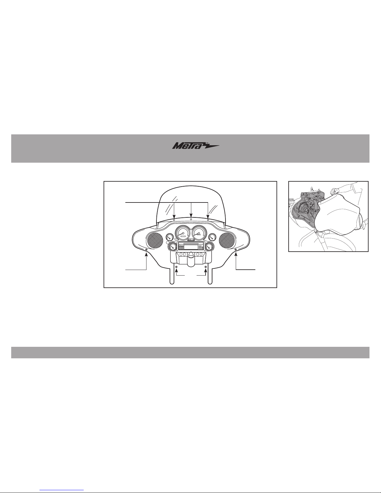
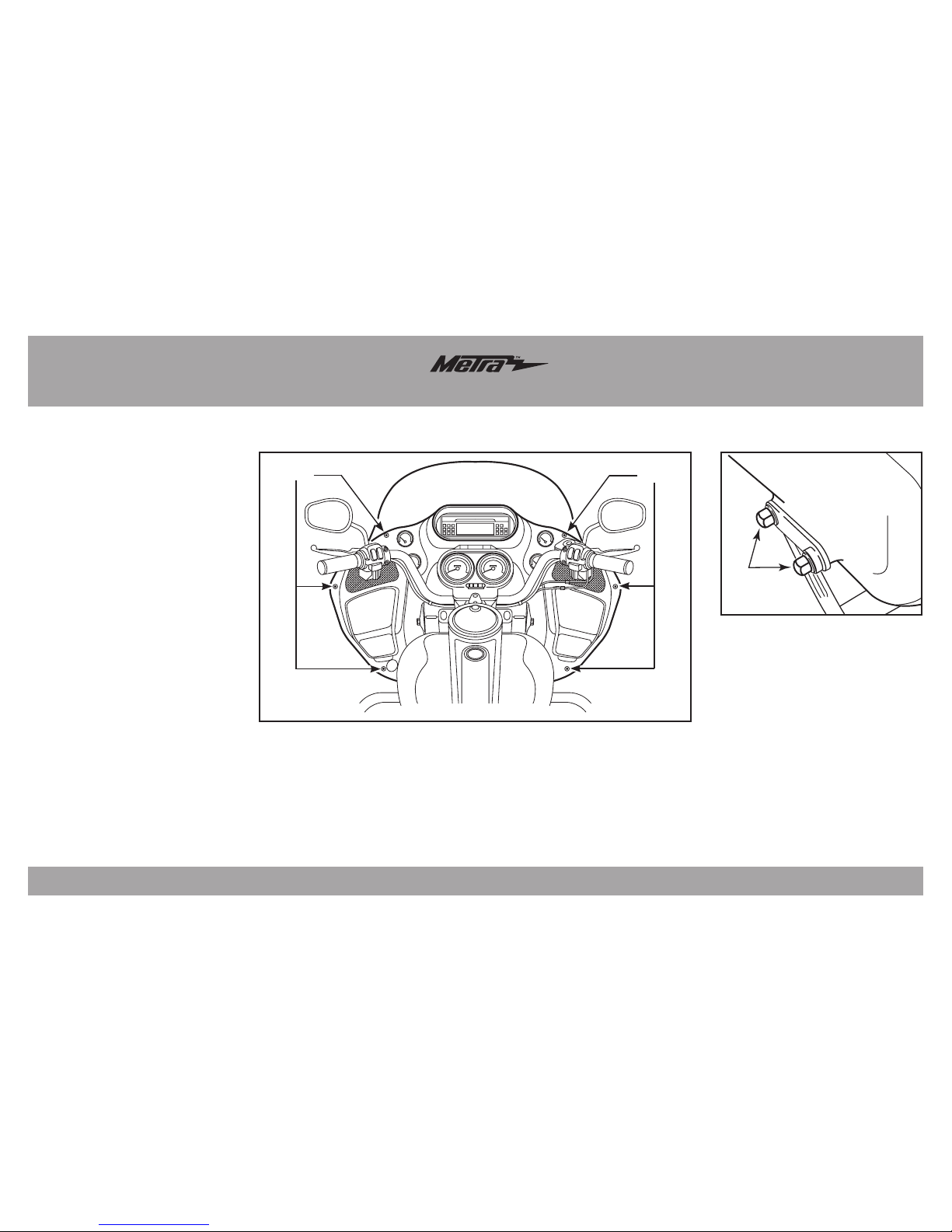
Desensamble del carenado................................ 3-4
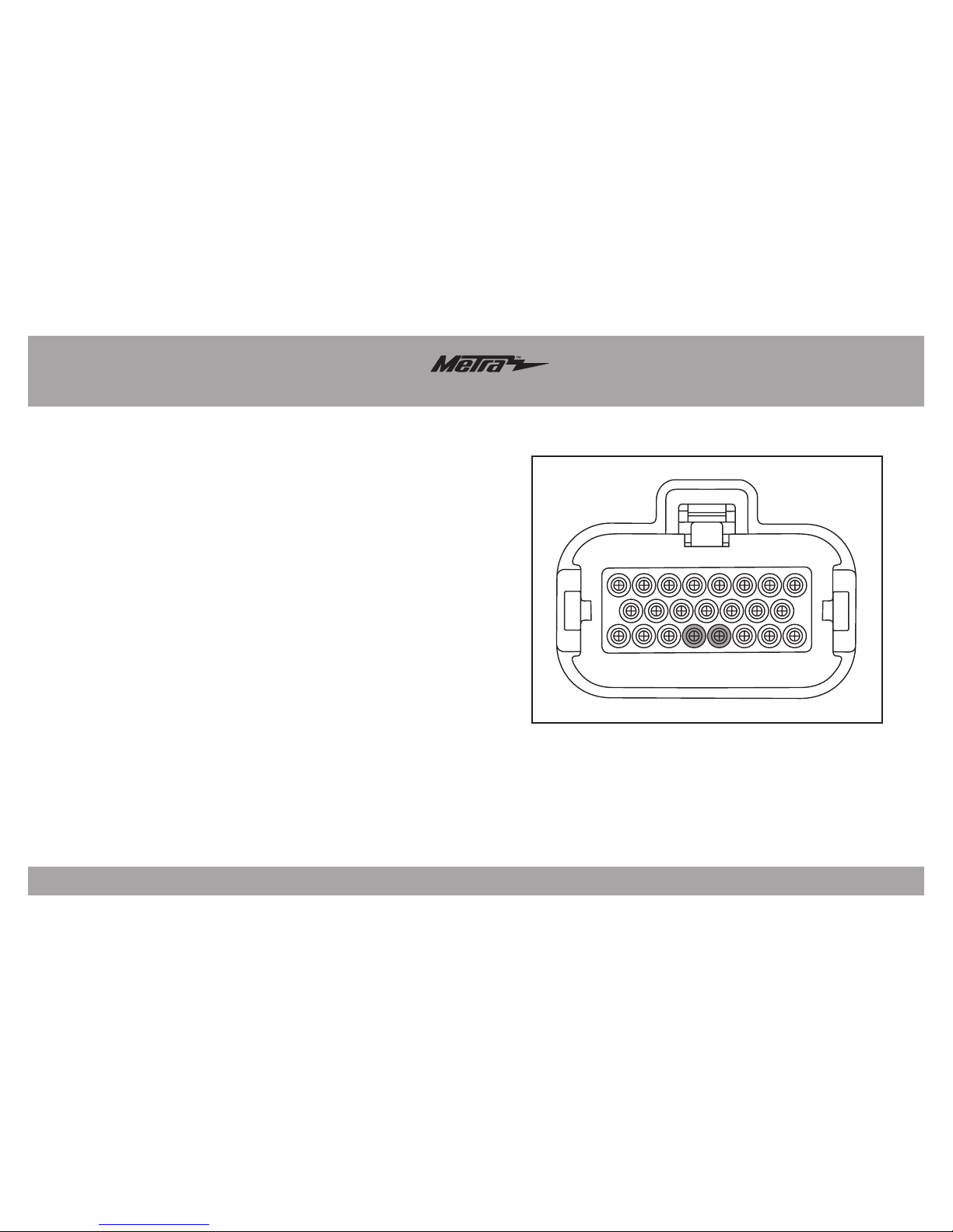
Conexiones que se deben hacer ............................5
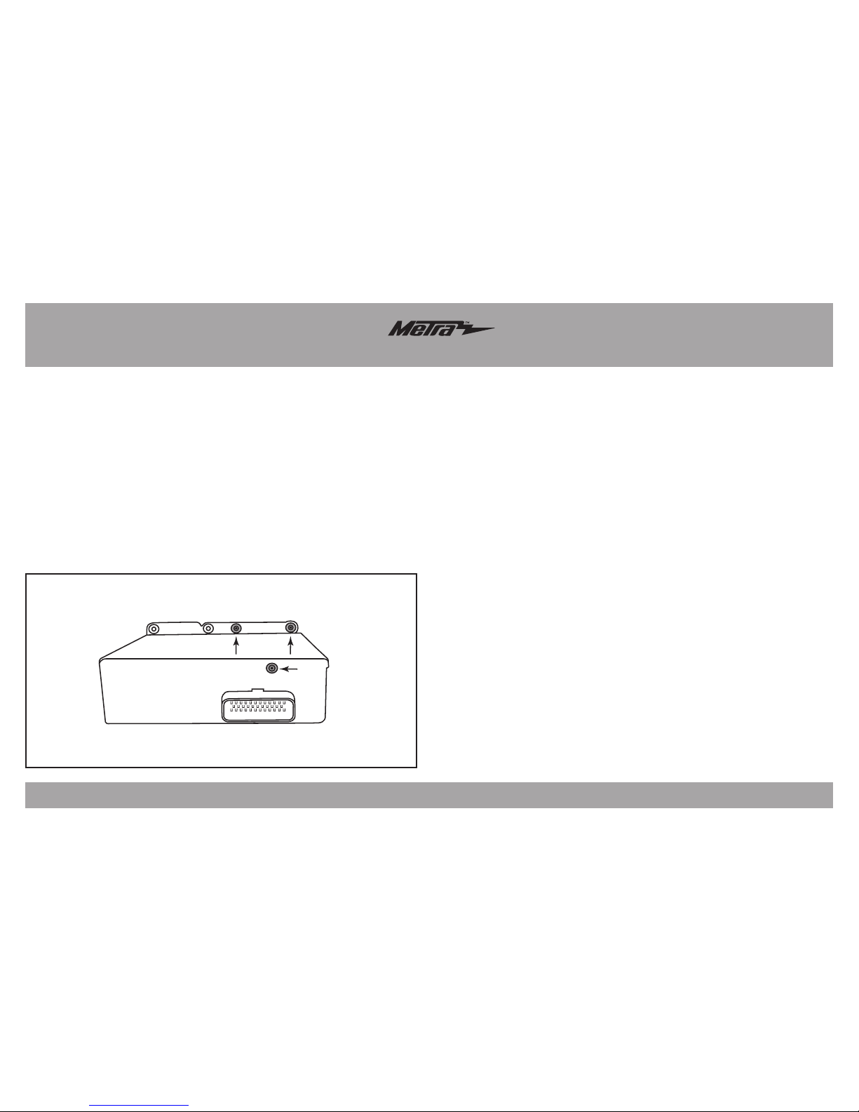
Instalación del BT-HD01 .........................................6
Emparejamiento del BT-HD01 ................................6
Operación................................................................6
APLICACIONES
HARLEY DAVIDSON (con Radio Avanzada)
Electra Glide 2006-2013
Street Glide 2006-2013
Road Glide 2006-2013

BT-HD01
2
Pre-Instalación
• Encienda el radio y active la fuente de FM.
• Ponga la llave de encendido en la posición de apagado.
• Presione sin soltar cualquiera de los (2) botones suaves del radio, luego gire la llave de encendido a la posición de encendido. Los botones suaves son los botones
numerados en el radio.
• Siga presionando los (2) botones suaves hasta que aparezca “Diag Test” en la pantalla del radio, luego suéltelos.
• Presione el botón suave “4” rotulado “Software” en la pantalla del radio.
• La pantalla del radio mostrará la versión de software actual. Si no tiene V8.250 o superior, vaya al siguiente sitio web para actualizar el radio:
http://www.harleydavidson.com/en_US/Content/pages/genuine_motor_accessories/advanced-audio-system.html
• Siga las instrucciones del sitio web exactamente como se indican. Si hay preguntas acerca del proceso, comuníquese con Harley Davidson. No se comunique con
Axxess/Metra para preguntas relacionadas con la actualización del radio.
• Si el radio tiene el software V8.250 o superior, presione el botón suave “6” para salir del modo de diagnóstico.
Atención: Antes de iniciar la instalación, revise la versión actual del software del radio siguiendo los pasos indicados a continuación.
Este producto no funciona en modelos con versiones de software inferiores a V8.250.

BT-HD01
3
Desensamble del carenado
Modelos FLH/alas de murciélago:
1.
Cubierta de la salpicadera delantera.
2. Retire (2) pernos T-27 Torx del
carenado interior (abajo de los
espejos). (Figura A, paso 2)
3. Retire (2) pernos T-27 Torx de los
bordes del carenado interior cerca
de los tubos de horquilla (orientado
hacia el frente) (Figura A, paso 3)
4. Retire (3) pernos T-27 Torx del
borde inferior del parabrisas.
(Figura A, paso 4)
Nota: El parabrisas y el carenado
estarán flojos después de retirar
estos tornillos. Tenga mucho
cuidado de no dañar el carenado o
el parabrisas.
5. Retire el parabrisas teniendo en
cuenta que el carenado exterior
está suelto.
6. Levante y desconecte el faro
delantero para retirar el carenado
exterior. (Figura B)
(Figura A)
(Figura B)
Paso 2 Paso 2
Paso 3
Paso 4

BT-HD01
4
Desensamble del carenado
Modelos Roadglide/Sharknose
1. Afloje (6) pernos T-25 Torx de la
parte inferior, media y superior
del lado derecho e izquierdo del
carenado interior. (Figura A)
2. Use una llave de cubo de 1/2” para
retirar las (2) tuercas ciegas que
sostienen cada señal direccional en
el carenado inferior. Deje colgando
las señales direccionales. (Figura B)
3. Levante el carenado, desconecte
los faros delanteros y retírelos.
(Figura A)
(Figura B)
Paso 1 Paso 1

BT-HD01
5
Conexiones que se deben hacer
• Retire el conector de 35 pins del radio. Es el conector más grande de los (2) conectores
que tiene el radio. Si el radio no tiene un conector de 35 pins, proceda al siguiente
paso.
• Conecte el extremo macho del arnés BT-HD01 en el radio.
• Conecte el extremo hembra del arnés BT-HD01 en el conector de fábrica del vehículo.
Si el radio no tenía un conector de 35 pins, omita este paso.
• Los siguientes (2) cables se conectan al conector del radio de 23 pins. Es el conector
más pequeño de los (2) conectores que tiene el radio. El conector de fábrica tiene las
ubicaciones de las cavidades de los pins estampadas en él.
• Conecte el cable negro del arnés BT-HD01 al cable localizado en el pin 19 del conector
del radio de 23 pins.
• Conecte el cable rojo del arnés BT-HD01 al cable localizado en el pin 20 del conector
del radio de 23 pins.
• Nota: El BT-HD01 puede operar en dos modos diferentes: modo CD (predeterminado)
o modo SAT. Si tiene una interfaz de iPod de fábrica instalada y desea conservarla,
cambie la unidad al modo SAT. Para hacerlo, necesitará cortar el cable de lazo gris
que sale del BT-HD01, y luego cambiar la conexión del cable de audio de 3 pins a la
configuración SAT.
18
16
23
19 20
Esta es la vista del cable del conector

BT-HD01
6
Controles en los manubrios
•
Los botones SUBIR y BAJAR operarán la canción siguiente/anterior, cuando corresponda
.
• El botón MODE SEL. ciclará entre las fuentes de audio disponibles.
Controles del radio
• Los botones suaves 1 a 6 le permitirán acceder a las siguientes funciones:
Emparejar (1), Reproducir/Pausa (2), Aleatorio (3), Siguiente (4)
Nota: Después de 5 segundos sin presionar ningún botón, el radio volverá de
manera predeterminada a la pantalla principal.
Nota: El BT-HD01 es compatible con el texto completo de la pantalla del radio
de la mayoría de las aplicaciones de streaming, siempre y cuando el dispositivo
Bluetooth sea compatible con AD2P.
Operación
Emparejamiento del BT-HD01
• Ponga la llave de encendido en la posición de encendido y luego encienda el
radio. Habrá una nueva opción en la pantalla del radio llamada “HDBT”.
• Seleccione esta opción y luego seleccione “Emparejar”.
• En el dispositivo Bluetooth, busque “HDBT” y empareje con el BT-HD01.
• Quite los (3) tornillos Torx del radio. (Figura A)
• Coloque el BT-HD01 en el radio, luego reinstale los (3) tornillos Torx, sujetando
el BT-HD01 al radio.
• Si desea utilizar el cable USB impermeable de 4’, enrute el cable para que
salga del carenado inferior al lugar deseado. El cable USB está diseñado para
montarse con un orificio perforado en el carenado, si se desea.
• Vuelva a armar el carenado al revés de como lo desarmó.
Instalación del BT-HD01

BT-HD01
7
Notas

METRA. The World’s best kits.™metraonline.com © COPYRIGHT 2004-2016 METRA ELECTRONICS CORPORATION
REV. 2/9/2016 INSTBT-HD01
KNOWLEDGE IS POWER
Enhance your installation and fabrication skills by
enrolling in the most recognized and respected
mobile electronics school in our industry.
Log onto www.installerinstitute.com or call
800-354-6782 for more information and take steps
toward a better tomorrow.
Metra recomienda técnicos
con certificación del Programa
de Certificación en Electrónica
Móvil (Mobile Electronics
Certification Program, MECP).
EL CONOCIMIENTO ES PODER
Mejore sus habilidades de instalación y
fabricación inscribiéndose en la escuela de
dispositivos electrónicos móviles más reconocida
y respetada de nuestra industria. Regístrese en
www.installerinstitute.com o llame al
800-354-6782 para obtener más información y
avance hacia un futuro mejor.
Instrucciones de instalación para la pieza BT-HD01
IMPORTANTE
Si tiene dificultades con la instalación
de este producto, llame a nuestra línea
de soporte técnico al 1-800-253-TECH.
Antes de hacerlo, revise las instrucciones
por segunda vez y asegúrese de que la
instalación se haya realizado exactamente
como se indica en las instrucciones. Por
favor tenga el vehículo desarmado y listo
para ejecutar los pasos de resolución de
problemas antes de llamar.
Table of contents
Languages:
Other Metra Electronics Accessories manuals
Popular Accessories manuals by other brands

GLD Products
GLD Products VIPER 42-1035 instructions

Black Box
Black Box AC063A manual

Heath Zenith
Heath Zenith Wireless Push Button Accessory SL-6190... owner's manual

Phil & Teds
Phil & Teds Peanut instructions

Multitech
Multitech Reveal RBS301-TILT-US user guide

MD SPORTS
MD SPORTS BBG030 018E V2 Assembly instructions