MPS-DPSL-BT
INSTALLATION INSTRUCTIONS
MetraPowerSports.com © COPYRIGHT 2020 METRA ELECTRONICS CORPORATION REV. 9/24/20 INSTMPS-DPSL-BT
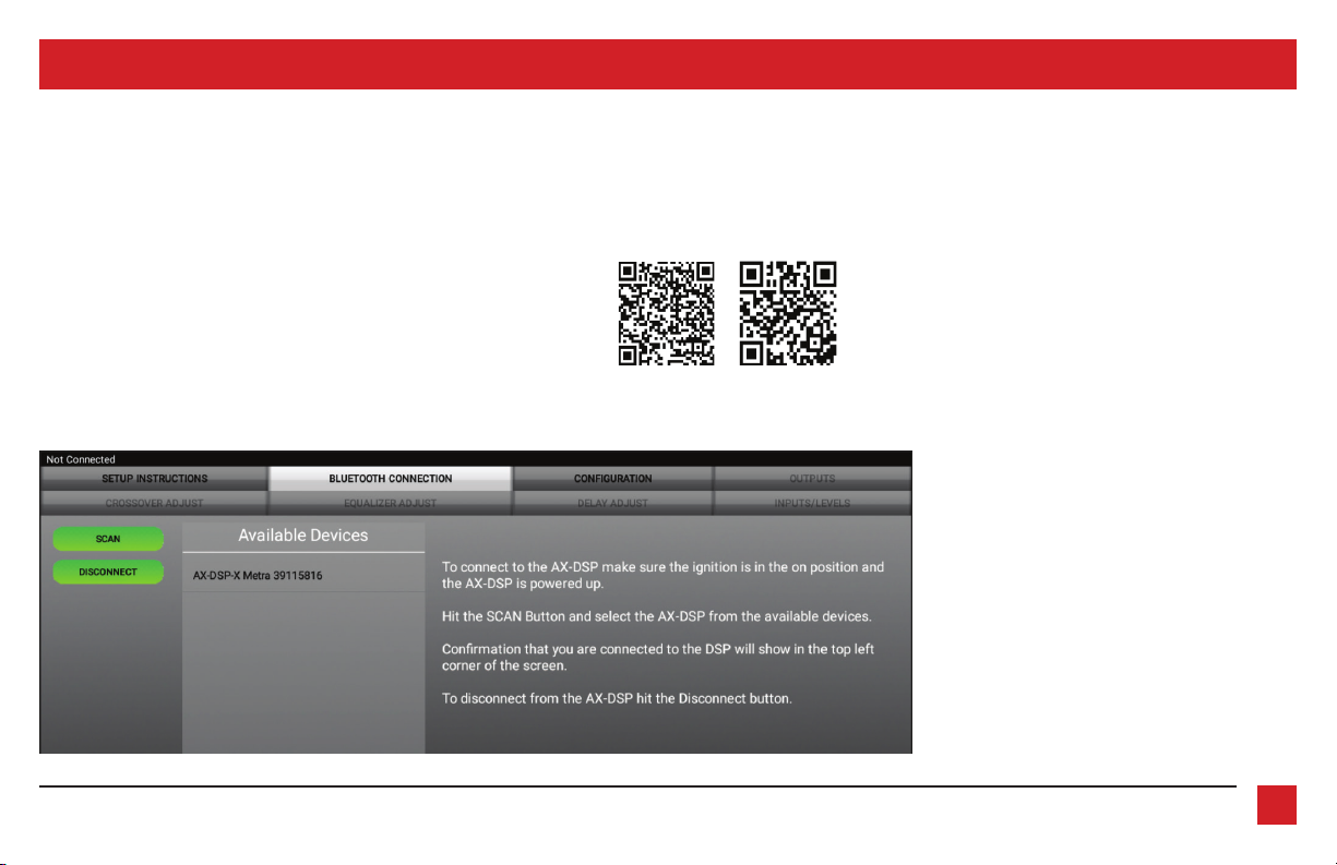
Google Play Store Apple App Store
iOS 12.1 or higher
INTERFACE FEATURES
INTERFACE COMPONENTS
TOOLS & INSTALLATION ACCESSORIES REQUIRED
• Crimping tool and connectors, or solder gun,
solder, and heat shrink • Tape • Wire cutter
• Zip ties • Multimeter
TABLE OF CONTENTS
Preface ....................................................................2
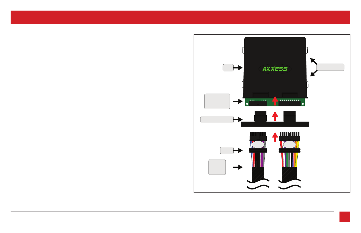
Installing bluetooth board ....................................3
Pinout .....................................................................4
Installation .............................................................5
Stand-alone bluetooth diagram ..........................6
Quick setup guide ..............................................7-12
Advanced DSP features & control options .....13-14
Other installation options ....................................15
Specifications ....................................................... 16
Marine & Powersports Bluetooth Streaming
Audio Interface w/ DSP Controls
No Source Needed.
• 15 Band graphic EQ
• Bluetooth streaming from your smart device
• 4 inputs and 6 outputs, including front, rear, and subwoofer
• Independent equalization for front, rear, and sub
• Independent crossover for front, rear, and sub
• Selectable slope (12, 24, 36, or 48db per octave)
• Front and rear channels can be delayed independently up to 10ms
• Water resistant enclosure with zip tie mounts included
• Clipping detection and limiting circuits
• Bluetooth interface module included
• Volume knob & Bass knob included
•
Settings adjusted via Bluetooth® in a smart device application (tablet
or mobile phone), compatible with both Android and Apple devices
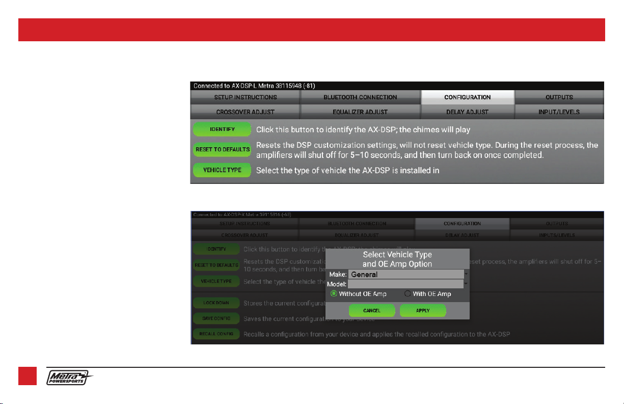
• Read, write, and store configurations for future recall
• Password protect feature available in the mobile app
• Micro-B USB updatable
• MPS-DSPL-BT circuit board
• Bluetooth streaming audio circuit board
• Volume and Subwoofer knobs
• MPS-DPSL-BT harness (16-pin & 20-pin, with gaskets)
• MPS-DPSL-BT enclosure
• Case
• Cap (with O-ring)