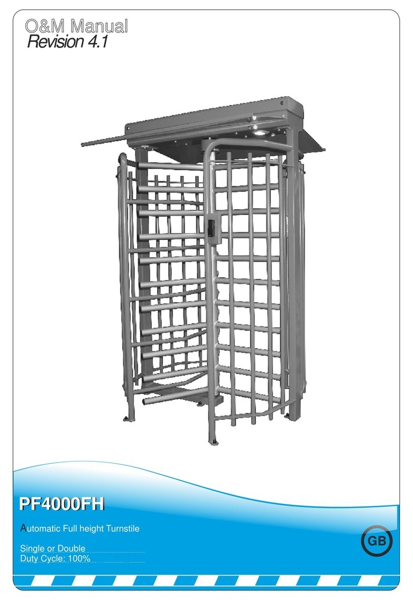
O&M D4150 User manual

120 Rotor
100 % Duty cycle
Made in
the
Full Height Turnstile
D4150

Introduction and Warnings
This equipment is part of a large range of traffic flow products. They are designed to be easy to install, as
all settings and internal wiring have been completed in our factory. Any of the instructions in this manual
should only be carried out by a qualified service engineer or a competent person.
The turnstiles are ready to bolt down, connect to a single phase power supply and have any access
control wired into them (Please note that advice should be sought on wiring instructions). The steps must
be completed before the power is turned on to prevent accidents.
The following information is a guide only, and whilst we have made every effort to be accurate and correct
there may be errors which we cannot be held responsible for.
With a correct installation you can expect to enjoy many years of reliable service from this product, we do
however recommend that the product has a bi-annual service carried out by a qualified engineer. Please
contact our service department to obtain a quote. As we manufacture the products we are best suited to
care for your equipment.
Thank you for your custom and welcome to the exciting world of Total Traffic Flow Solutions.
/ /
20
Important Safety Notice
Automatic turnstiles are designed to Control the flow of human
traffic only. It can be dangerous to allow the passage of any
other self-powered animal or device to utilise this method of
access without appropriate warnings and or signage.
It may be necessary for the end user of this product to provide
an alternative, safe method of access to cater for the previously
mentioned categories.
The end user should fit all necessary signage and warning
notices to either side of the turnstile, which should be visible and
clear from all directions of approach.
The product that was shipped to you was designed with a control
program to protect all categories from harm or affect this
however is only a precaution. It should not be modified or
tampered with by any unauthorised person not sanctioned by the
manufacturer.
Please sign and date below to say that you have read and
understood this notice before ANY installation work:
The “Warnings” leaflet and “Instruction booklet” supplied with this
product should be read carefully as they provide important information
about safety, installation, use and maintenance.
Scrap packing materials (plastic, cardboard, polystyrene etc) according
to the provisions set out by current standards. Keep nylon or polystyrene
bags out of children's reach.
Keep the instructions together with the technical brochure for future
reference.
This product was exclusively designed and manufactured for the use
specified in the present documentation. Any other use not specified in
this documentation could damage the product and be dangerous.
The Company declines all responsibility for any consequences resulting
from improper use of the product, or use which is different from that
expected and specified in the present documentation.
Do not install the product in explosive atmosphere.
The construction components of this product must comply with the
following European Directives: 89/336/CEE, 73/23/EEC, 98/37/EEC
and subsequent amendments. As for all non-EEC countries, the abovementioned
standards as well as the current national standards should
be
respe
ct
ed
i
n or
d
e
r to achieve a good s
a
fety level.
Information on using
this manual
Read all information thoroughly
Pay attention to all safety advice
Be aware of the symbols (shown above right and above
left) as they have different meanings. One is an
information symbol, the other a warning.
There are many artists impressions of the product in this
manual you should refer to the images as a guide only.
Professional CAD drawings should be used as a
reference drawing and nothing else. As before every
effort has been made to be 100% accurate in this
manual but we cannot make any guarantees.
As we constantly innovate our products we may change
the quoted spec and any other details that have been
documented in this manual so you should always refer
to the supplier to see if the manual that was shipped
with your product is the latest edition.
As with all electrical installations you should use a
qualified electrician and obey all of the latest laws and
regulations.
Be sure to fill out and complete ALL paperwork where
instructed as this manual is the equipments log book
and maintenance manual.
The Company declines all responsibility for any consequences resulting
from failure to observe Good Technical Practice when constructing
closing structures (door, gates etc.), as well as from any deformation
which might occur during use.
The installation must comply with the provisions set out by the following
European Directives: 89/336/CEE, 73/23/EEC, 98/37/EEC and
subsequent amendments.
Disconnect the electrical power supply before carrying out any work on
the installation. Also disconnect any buffer batteries, if fitted.
Fit an omnipolar or magnetothermal switch on the mains power supply,
having a contact opening distance equal to or greater than 3mm.
Check that a differential switch with a 0.03A threshold is fitted just before
the power supply mains.
Check that earthing is carried out correctly: connect all metal parts for
closure (doors, gates etc.) and all system components provided with an
earth terminal.
Fit all the safety devices (photocells, electric edges etc.) which are
needed to protect the area from any danger caused by squashing,
conveying and shearing, according to and in compliance with the
applicable directives and technical standards.
D4150

Incorrect Correct
Delivery,Movement & Transportation
The Turnstile should ALWAYS! be moved with care and attention. The products are very heavy individually
as well as a whole. Y ou should not attempt to move this or any other products by unapproved handling
methods.
This article describes how your equipment will be delivered to you, specifications on the transportation
used and advice including health & safety on movement of the equipment.
The manufacturer will use a qualified transport company to deliver the product conforming to the
necessary regulations as detailed below:
All drivers are qualified
All drivers are tested once yearly
All drivers carry risk assessments and method statements (available on request)
They are controlled under law to conform as there are no trade regulation standards to comply with
Health and safety Considerations:
Moving Goods Safely (MGS) is a national project involving both the Health and Safety Executive (HSE) and
Local Authorities (LA) working in partnership. The project aims to reduce injuries and ill-health arising from the
movement of goods from supplier through haulier to the recipient and end user including any home deliveries.
The project will focus upon the delivery and collection of goods and the hazards this generates. It covers the
main areas that cause the majority of injuries and ill-health to workers, including:
Workplace transport;
Slips & trips, and;
Musculoskeletal disorders (MSD).
The movement of goods presents us, as health and safety regulators, with the challenge of dealing with a huge
variety of issues. The commercial organisations involved within the movement of goods are diverse including
haulier, third party logistics providers, pallet networks, retailers etc, with some very large companies,
thousands of small businesses and the self-employed. The movement of goods is more than just trucks on the
road with a large proportion of accidents happening at the delivery/collection sites that are often not directly
under the control of the company making the delivery or collection. Communication and cooperation problems
can arise due to the many organizations involved in the movement of the goods, and this can also lead to
difficulties in effectively managing health and safety.
(Source H&S Executive UK 2008)
D4150

3
1
4
To assemble the turnstile follow the steps below.
1. Now insert the rubber
mounts in between the
4x rotor bolts and the
head Mechanism.
2. Then place the kidney
washers over and secure
using M16 Nylock Nuts.
2
Component Identification and Notes:
You should check that you have received the following in your order as they are referred to throughout this
manual (note this can change per barrier spec i.e. manual components are different from automatic):
Follow the steps below for Installation.
Guide to Physical Installation
Please note all installations should be carry out by a competent person and all electrical
Connections should be made by a qualified electrician.
When delivered, the Turnstile will either be on a
Pallet or flat packed. If flat packed then follow
Step’s 2-4, if already assembled carry on to step 5.
Note - please check for physical damage before
You sign.
Turnstile Box
of
bits
C/w O and M
manual
7 x M12 x 120 Parabolts
2 x Manual release keys
1. Bolt down side 1 into the
desired position.
2. Measure, mark out and
bolt down side two.
3. Ensure both sides are
level and are correctly
spaced apart.
4. Place the rotor onto the
bottom bearing and hold
in place ready for the top.
1. Now make sure the rotor
is in the correct position
as shown below.
2. Once you have the 4x rotor
bolts lined up, Using the
correct lifting equipment lift
the top onto the two sides
and rotor making sure the
4x rotor bolts locate through
the head mechanism.
3. Now bolt the top to the sides
using the M12 bolts supplied.
3. Now fit the Rotor plates
using the M6 button
head bolts.
D4150

7
earth product
Notes area
Guide to Physical Installation (Cont)
5 Tak ing into con s ide r ati on th at t h e plinth has been 6 Once you have the Turnstile in position and
Have checked that it is all level, Bolt down side
2 using M12 parabolts supplied. Then check
For alignment and measure between the two
Sides to make sure its that same distance as
At the top of the Turnstile, Then carry on and
Drill and fix the rest of the fixing points.
Now make sure you have tightened all the fixings
And that the Turnstile is level and is under no
Stress. You can then place the plastic caps on
The bolts.
8 You are ready now to connect up Mains supply
And access control using the diagram on page
8. Once you have everything connected, Check
All connections are tight and correct. Then switch
Power on and test.
Once you have completed all tests now fit the top cover and secure with M6 button heads. Make sure the
Turnstile is safe to leave working. Now fill out the commissioning certificate on the Next page.
9
Prepared correctly and is absolutely level and true,
Lower the turnstile onto the plinth and visually align.
Make sure you have pulled all cables through the
Box section into the top of the turnstile and ensure
No cables are trapped ready to bolt down.
Remove the button head
screws and plate to gain
Access to the cable routes.
D4150

We certify that the system covered by this certificate has been commissioned satisfactorily.
Site Name
Site Reference
Installation Commenced / /20
Completion
Engineers Installing
Commissioning
Equipment Fitted
Handover Date
Part 2. Existing Installation Items not covered under warranty/ This certificate:
Installers Name
On Behalf of
Address
Signature
Date of Signing
Position
Part 3. Certificate Signing off Section
Client Name
On Behalf of
Site Address
Signature
Date of Signing
Position
Commissioning Certificate
D4150

Electrical Troubleshooting Guide
Please use the following instructions to operate the barrier manually, the following
is assuming you have powered down the unit and opened the cabinet door:
Turnstile Maintenance
Manual Release
To Manually release the Turnstile, Turn the entry or exit key switch clockwise to release the
rotor into free wheel. The key switches are located underneath the main header just above the
rotor as illustrated below.
As stated at the beginning of this manual we recommend a bi-annual service, but at a bare minimum, it is imperative
that you get a service done once every 12 months. This is not a sales tactic in disguise, there is a very serious
health and safety issue/risk associated with not complying to this. Also in order for your equipment to keep
complying with the appropriate legislation.
Before carrying out any maintenance to the installation, Isolate the mains power supply.
Make sure you have disconnected/Isolated the power before attempting any work.
A Maintenance Contract should be sought from a specialist company after a maximum of 5000 manoeuvres or
1year from the install date.
Have a qualified technician (installer) check the correct setting of the electric clutch.
If the power supply cable is damaged, it must be replaced by the manufacturer or its technical assistance service,
or else by a suitably qualified person, in order to prevent any risk.
When any operational malfunction is found, and not resolved, disconnect the mains power supply and request the
assistance of a qualified technician (installer). When automation is out of order, activate the manual release to
allow the opening and closing operations to be carried out manually.
Bearing units are “sealed” for life and require no further lubrication.
D4150
D4150

Connection T
erminals/Layout
PLC
24VDC
Power supply
D4150

Note:
Depending which way the turnstile has been installed the entry/exit may be the opposite way round,
This will not affect the operation in any way.
The table (bottom) relates to the diagram directly below to help you trouble shoot electrical component errors
Example 2
Inputs 1 and 4 are highlighted
Which indicates that the stop
Circuit and raise limit is
Activated as shown in the
Table below
Example 1
There are Several Faults
Texts std in the program
Which will appear on the
PLC screen to help
Diagnose the fault.
If the Screen is not showing
A fault then Press the right
Arrow key once and the
Input screen will appear
As shown in Example 2.
1. Inputs
Input Polarity Connected to Operation when active
I1 Normally Open Free wheel Free wheels in both directions
I2 Normally Open Entry signal Allows one person through the entry of the turnstile
I3 Normally Open Exit signal Allows one person through the exit of the turnstile
I4 Normally Open Entry limit switch Switches solenoid off after one person is through
IB Normally Open Exit limit switch Switches solenoid off after one person is through
IC Normally Open Lock signal Locks the turnstile in both positions electrically
ID Normally Open Spare
IE Normally Open Spare
2. Outputs
Output: Polarity: Connected to: Operation when active:
Q1 Normally Open Entry Solenoid Activates Entry solenoid
Q2 Normally Open Exit Solenoid Activates Exit solenoid
Q3 Normally Open Down lights Controls down lights(if fitted) from Plc timeclock
Q4 Normally Open Spare
!
Electrical Troubleshooting Guide
D4150

ELECTRICAL ERRORS CAUSE CORRECTION
MECHANICAL ERRORS CAUSE CORRECTION
Turnstile is free wheeling Paddles are not latched in check manual release keyswitches
Rotor is not spining Check bearings top/bottom Oil or grease bearings
Blank screen on PLC but power to other devices
in the control panel
On-board fuse blown Replace fuse and reset barrier
PLC has developed an electrical fault or had a
power spike
Change PLC
Troubleshooting Guide
Rotor has a lot of play when locked Check paddle bolts Tighten both paddle bolts
Turnstile making grinding noise Top Cog/Spring assist requires lubrication Lubricate both items
Turnstile Rotor is tight Turnstile is out of square/level check turnstile/frame is all square/level
Turnstile Rotor is tight Bottom bearing is ceased Replace bottom bearing
Turnstile Free wheels
If fail safe turnstile then solenoids may
have no power Check solenoid relay and replace if faulty
If fail secure turnstile then solenoids may
Have permanent power Check solenoid relay and replace if faulty
Turnstile lets more then one
Person pass through
Limit switches are not working Adjust position of limit or replace if faulty
Access control signal set too long Turn access signal down to 1 second
No 24DC to Plc or other devices
24V PSU faulty Change PSU
Blown fuse Replace fuse
D4150

Date Reason for visit/Action taken Engineers Signature
/ /20
/ /20
/ /20
/ /20
/ /20
/ /20
/ /20
/ /20
/ /20
/ /20
/ /20
/ /20
/ /20
/ /20
/ /20
/ /20
/ /20
/ /20
This Manual must be completed in accordance with the guidelines below, at any point service/repair
work is carried out on the product. This is to achieve two things;
1. To keep a history of the product for yourself and your supplier/manufacturer.
2. To keep an accurate log of any historical or recent modifications, and/or problems, to help an
engineer in the event of any future work required on the product.
3. This page is continued on the next page if extra space is needed.
!
Service Log
D4150

Accessories
Optional extras:
Directional Flow indicator lights
Canopy Lights
Siren/Sounder
Bespoke Signage
Specification
M a d e i n t h e U K
Technica Data
Dimensions:
Frame: 1520 mm x 1360 mm x
2230 mm
Rotor: 120 mm Ø tube with
bottom support bearing
Arms: 50 mm Ø tube with
Domed capped ends
Side frames: 50 x 20 Rolled
Box section welded 80 box
Uprights.
Specification
Power Requirement:
Arms and body:
Duty Cycle:
Flow Rate:
Key Points:
Access Controls:
220 v, Single Phase, 50 Hz, 5 Amps
Primed/Powder Coated finish
100% continuous duty rating
15 to 22/min in a single direction
Bi-Directional control Fail safe or Fail secure, Factory
settings need no adjustment, PLC controlled can work with all
access and revenue systems, cable routes through side frames,
Turnstiles will suit interior and exterior installations.
Push-button, Proximity cards, card readers,
tokens, voice/video intercoms, keypads and remote fobs.
D4150
Table of contents
Other O&M Turnstile manuals
Popular Turnstile manuals by other brands

BOON EDAM
BOON EDAM Turnlock 100 Safety and operation instructions

Magnetic
Magnetic MPB-311 operating instructions

Magnetic Autocontrol
Magnetic Autocontrol MPT-132 operating instructions

Oxgard
Oxgard Praktika T-01 Installation guidelines

Makim
Makim T2500D SINGLE 3 user manual

PERCo
PERCo TTD-03.2 Operation manual